Nomenclature
- A
-
disk area
- A k
-
kth-order frequency component’s amplitude of aerodynamic moment
- b
-
crcumferential blade width
- B k
-
kth-order frequency component’s amplitude of flapping angle
- Cl
-
aerofoil lift coefficient
- I y
-
flapping inertial moment
- M T
-
ferodynamic flapping moment
- m 0
-
blade
- N
-
rotation speed
- R
-
rotor radius
- R 0
-
flap-hinge radial position
- r
-
radius location
- r k
-
radius location of the kth sector
- T
-
total thrust
- t
-
time
- V
-
inflow velocity
- v i
-
induced velocity
- V k
-
inflow velocity of the kth sector
- V x
-
parallel inflow component to the rotor disk
- V z
-
vertical inflow component to the rotor disk
Greek symbol
-
 $\alpha$
-
angle-of-attack of the disk
-
$\alpha$
k
-
angle-of-attack of the kth sector
-
$\beta$
-
flapping angle
-
$\epsilon$
-
flap-hinge offset
-
$\theta$
-
geometrical setting angle
-
$\theta$
k
-
geometrical setting angle of the kth sector
-
$\rho$
-
air density
-
$\varphi$
-
angular position
-
$\varphi$
k
-
inflow angle of the kth sector
-
$\omega$
-
rotating angular speed


1.0 Introduction
Helicopters are widely used in many fields due to their capability for vertical takeoff/landing and stationary hovering. However, a persistent shortcoming of a helicopter is its relatively high vibration level during flight (e.g. 0.2 g for a helicopter vs. 0.05 g for a fixed-wing aircraft), which is mainly caused by periodic aerodynamic forces acting on the rotor blades and the resultant blade movements.
During the flight of a helicopter, the aerodynamic forces on the blades and the hub moment transmitted to the fuselage both vary periodically with the angular position of the blades, which can affect the stability of the helicopter flight and could generate transient loads on the fuselage structure and onboard equipment. Once the time-varying pattern of the aerodynamic forces could be precisely determined, targeted design could be performed on the cyclic pitch control law, airborne equipment and fuselage structure to decrease flight vibration and to increase ride comfort.
However, one of the greatest difficulties in calculating the blades’ transient aerodynamic forces is the bidirectional coupling between aerodynamic forces and flapping deformation. Specifically, the aerodynamic forces cause the flapping angle, which in turn significantly affects the dynamic force. This phenomenon makes it difficult to calculate the forces and displacements using traditional methods to solve the dynamic equations unidirectionally.
Several different methods have been presented recently in order to calculate how the aerodynamic forces and the flapping angle change with the blades’ angular position. Wall calculated the effect of the forward-aircraft wake ahead and the related additional control, and his article contains a flapping angle calculation under the forward-aircraft wake effect [Reference van Der Wall1, Reference van Der Wall2]. Wang embedded several sensors on the fuselage and presented a mathematical model to calculate real-time flapping angle based on a high-gain observer [Reference Wang, Huo, Ma, Xie and Liu3]. Perdomo compared two different methods to solve the flapping dynamic differential equation and indicated that there could be larger errors if some high-order frequency components are not taken into account [Reference Perdomo and Wei4]. Lopez combined Floquet theory and the Equivalent Linear Time Invariant model, and calculated the parameters, including amplitude, of different frequency components based on conventional eigenvector analysis [Reference Lopez and Prasad5]. Sunada formulated the dynamic equation containing flapping angle and dynamic moments and calculated the flapping angle with blades’ angular position by solving the second-order differential equation [Reference Sunada, Sumino, Matsue and Tokutake6]. Majhi also used blade-element theory to calculate the aerodynamic forces and indicated that the small-angle hypothesis may cause a large error [Reference Majhi and Ganguli7]. Castillo-Rivera used VehicleSim software (Version 1.0) to calculate the flapping and pitching movement of a tail rotor, whose flapping motion could be a bit simpler than that of main rotors [Reference Castillo-Rivera and Tomas-Rodriguez8]. Jiao embedded a few sensors on a blade to measure the deformation to acquire the aerodynamic force; however, his article mainly focused on the radial load distribution instead of the azimuth distribution [Reference Jiao and Zheng9]. Gu used the modal orthogonality and the equilibrium equation of the blade flapping motion to calculate the effect of rear-edge flaps on different frequencies [Reference Gu, Dong, Li and Yang10].
Due to the dynamic stall phenomenon during the flapping motion, a traditional single-valued lift curve might be inapplicable. In order to calculate aerodynamic force accurately, several methods have been presented. Wall compared the variation of several parameters along flight conditions, such as flying speed, and presented a method to correct mathematical models with varying flight conditions [Reference van Der Wall2]. Müller tested the flapping variation along angular position under different flight conditions and measured several parameters such as blade bending moment and surface pressure [Reference Müller, Braukmann and Weiss11]. Küppers trained a neural network with flight data of several types of rotors to calculate dynamic stall parameters of other types of rotors [Reference Küppers and Reinicke12]. Santos improved the Beddoes–Leishman dynamic stall model and achieved a higher accuracy with a longer calculation time and cost [Reference dos Santos and Marques13]. Majhi compared simulations with and without the small-angle assumption [Reference Majhi and Ganguli7].
However, the studies mentioned above mainly solve the differential equation for the flapping angle, which might lead to divergence or impractical results under some flight conditions. This article presents a method to calculate the variation in the flapping angle and aerodynamic force along the blade’s angular position. The aerodynamic moment M
T
is first calculated using blade-element theory, and the Fourier transform is used to express both M
T
and flapping angle
 $\beta$
as a summation of several frequency components. Both M
T
and
 $\beta$
are substituted into the flapping differential equation, and each pair of amplitudes of the same frequency components is compared to calculate unknown parameters in the expression of
 $\beta$
. Finally, the result for
 $\beta$
is substituted into the blade-element aerodynamic equation, and a new M
T
is obtained. This process is repeated until both M
T
and
 $\beta$
converge.
2.0 Blade flapping dynamic model
Flapping helicopter blades have a unique character: bidirectional coupling between aerodynamic loads and flapping deformation, namely, the aerodynamic forces cause the flapping angle, which in turn affects the dynamic force significantly. Due to this phenomenon, traditional methods of solving dynamic equations unidirectionally might fail when dealing with helicopter blades, making iterative step-by-step methods necessary.
The flapping dynamic equation is shown below:
 \begin{align} \frac{\mathrm{d}^{2}\beta }{\mathrm{d}t^{2}}+(1+\varepsilon)\omega ^{2}\beta =\frac{M_{T}}{I_{y}} \\[-30pt] \nonumber \end{align}
 \begin{align}\varepsilon = \frac{\big(\frac{R_0}{R}\big)S_\beta}{I_y}\end{align}
where t stands for time,
 $\beta$
stands for the flapping angle, M
T
stands for the aerodynamic flapping moment around the flapping hinges,
 $\omega$
stands for the angular speed of the rotor shaft,
 $\epsilon$
stands for the flap-hinge offset and I
y
stands for the moment of inertia. The geometrical relationships among the variables can be seen in Figure 1.
Due to the bidirectional coupling characteristic, the following processes (see Figure 2) are adopted.
Main parameters in flapping motion.

Iteration process.

-
1. Assuming an initial flapping angle (e.g. a constant value of 0°) and calculating the M T regularity along the blade angular position based on the blade element theory.
-
2. Substituting M T into (1) and calculating the flapping angle
$\beta$
regularity along the blade angular position. -
3. Calculating the M T curve based on
$\beta$
again. -
4. Repeating steps 2 and 3 until both M T and
$\beta$
do not change with iteration.


Because some intermediate variables might be close to zero, a real solution may not exist. Meanwhile, the expected phase difference between the flapping angle and the aerodynamic moment may not be obtained. This article compares each frequency component to solve the equation.
First, the aerodynamic moment M T is expressed as
 \begin{equation} M_{T}=A_{0}+A_{1}\!\cos\!(\omega t)+A_{2}\!\sin\!(\omega t)+\ldots +A_{2k-1}\!\cos\!(k\omega t)+A_{2k}\!\sin\!(k\omega t) \end{equation}
The presentation is limited to the first three orders here for simplicity:
 \begin{equation} \begin{array}{l} M_{T} = A_{0}+A_{1}\!\cos\!(\omega t)+A_{2}\!\sin\!(\omega t)+A_{3}\!\cos\!(2\omega t)\\[3pt] \quad \qquad\!\!\! +\; A_{4}\!\sin\!(2\omega t)+A_{5}\!\cos\!(3\omega t)+A_{6}\!\sin\!(3\omega t). \end{array} \end{equation}
When ignoring the blade’s flexible deformation, the flapping motion can be regarded as a one degree-of-freedom (1-DOF) undamped forced vibration, whose natural frequency equals the rotation frequency
 $\omega$
, which means the phase difference between the flapping angle and the aerodynamic moment is
 $\pi$
/2 for the first-order frequency components, and
 $\pi$
for the second- and third-order components.
Then the flapping angle can be expressed by (5), where B k stands for the kth-order frequency component’s amplitude, and this component is driven by the aerodynamic moment whose amplitude is A k in (4).
 \begin{align} \beta &=B_{0}+B_{1}\!\cos\!(\omega t-\pi /2)+B_{2}\!\sin\!(\omega t-\pi /2)\nonumber \\[3pt]& \quad +B_{3}\!\cos\!(2 \omega t-\pi )+B_{4}\!\sin\!(2 \omega t-\pi )\nonumber \\[3pt]& \quad +B_{5}\!\cos\!(3 \omega t-\pi )+B_{6}\!\sin\!(3 \omega t-\pi ) \\[3pt] &=B_{0}-B_{2}\!\cos\!(\omega t)+B_{1}\!\sin\!(\omega t)-B_{3}\!\cos\!(2 \omega t)\nonumber \\[3pt] & \quad -B_{4}\!\sin\!(2 \omega t)-B_{5}\!\cos\!(3 \omega t)-B_{6}\!\sin\!(3\omega t) \nonumber \end{align}
Substituting (5) into the left side of (1) yields (6)
 \begin{align} \frac{\mathrm{d}^{2}\beta }{\mathrm{d}t^{2}} &+\left(1+\varepsilon \right)\omega ^{2}\beta \nonumber \\ &\begin{array}{l} =\left(1+\varepsilon \right)\omega ^{2}B_{0}(-\varepsilon \omega ^{2}B_{2}\!\cos\!(\omega t)+\varepsilon \omega ^{2}B_{1}\!\sin\!(\omega t)\\[3pt]\quad +(3-\varepsilon)\omega ^{2}B_{3}\cos\!(2\omega t)+(3-\varepsilon )\omega ^{2}B_{4}\sin\!(2\omega t)\\[3pt]\quad +(8-\varepsilon)\omega ^{2}B_{5}\cos\!(3\omega t)+(8-\varepsilon )\omega ^{2}B_{6}\sin\!(3\omega t). \end{array} \end{align}
Comparing the factors in (6) and (4), we can find that
 \begin{align} (1 + \varepsilon)\omega^2 B_0 &= \frac{A_0}{I_y} \nonumber \\[2pt] \varepsilon \omega^2 B_2 &= -\frac{A_1}{I_y}\nonumber \\[2pt] \varepsilon \omega^2 B_1 &= \frac{A_2}{I_y} \nonumber \\[2pt] (3 - \varepsilon) \omega^2 B_3 &= \frac{A_3}{I_y} \nonumber \\[2pt] (3 - \varepsilon) \omega^2 B_4 &= \frac{A_4}{I_y}\nonumber \\[2pt] (8 - \varepsilon) \omega^2 B_5 &= \frac{A_5}{I_y}\nonumber \\[2pt](8 - \varepsilon) \omega^2 B_6 &= \frac{A_6}{I_y}. \end{align}
In each iteration step, the aerodynamic moment M T is first obtained and then the component amplitudes can be calculated based on (6).
3.0 Mathematical model of aerodynamic force
It is relatively complicated to calculate the aerodynamic moment M T , which can be expressed as:
 \begin{equation} M_{T}={\int_{R_{0}}^{R}} \ 0.5\rho V(r)^{2}\left[Cl \ \!\cos \ \phi (r)\right]b(r-R_{0})\mathrm{d}r \end{equation}
When dividing the blade into n radius sectors of width dr, the equations below can be obtained:
 \begin{align} M_{T}=0.5b\rho V(r)^{2} \ \sum\limits_{k=1}^{n} \ {V_{k}}^{2}Cl \ \!\cos \phi _{k}\left(r_{k}-R_{0}\right) \\[-10pt] \nonumber \end{align}
 \begin{align} {V_{k}}^{2}=(\omega {r_{k}}+{V_{x}} \ \!\sin {\psi _{k}})^{2}+\left(\dot{\beta }{r_{k}}+{v_{i}}+{V_{Z}}\right)^{2} \\[-10pt] \nonumber \end{align}
 \begin{align} T=2\times 0.5b\rho V(r)^{2} \ \sum\limits_{k=1}^{n} \ {V_{k}}^{2}Cl \ \!\cos \phi _{k} \\[-10pt] \nonumber \end{align}
 \begin{align} \tan \ \varphi _{k}=\left(\dot{\beta }r_{k}+v_{i}+V_{Z}\right)/\left(\omega r_{k}+V_{x} \ \!\sin \psi _{k}\right) \\[-2pt] \nonumber\end{align}
 \begin{align} \alpha_k = \theta_k - \varphi_k \quad \quad \quad \\[-8pt] \nonumber \end{align}
 \begin{align} T=2\rho A{v_{i}}^{2}\sqrt{(V_{Z}+v_{i})^{2}+{V_{x}}^{2}} \\[10pt] \nonumber \end{align}
In the equations above, Cl is the aerofoil lift coefficient, r
k
is the radius location of the kth sector,
 $\alpha$
k
is the angle-of-attack of the kth sector,
 $\theta$
k
is the pitch angle of the kth sector,
 $\varphi$
k
is the inflow angle of the kth sector, V
k
is the inflow velocity of the kth sector, b is the circumferential blade width, dr is the radius sector width,
 $\rho$
is air density, T is the total thrust (for a two-bladed rotor as an example) perpendicular to the disk plane, v
i
is the induced velocity perpendicular to the disk plane (taken as a single value under the uniform inflow assumption) and A is the rotor disk area.
For the momentum-theory-based induced velocity with flying speed V
a
and rotor disk angle-of-attack
 $\alpha$
, the velocities are shown in Figure 3. The flying speed is divided into in-plane velocity V
x
and vertical speed V
z
.
Inflow velocity composition.

Velocity composition on the blade section.

Velocities on each blade section are shown in Figure 4. The pitch angle
 $\theta$
is the geometrical setting angle and varies periodically under control of the flight control system.
By solving the equations above, the aerodynamic forces on each section and the aerodynamic moment M T at each angular position can be obtained. The whole process is described below and is summarised in Figure 5:
-
1. Inputting flying speed Va and pitching angle
$\theta$
(
$\varphi$
). -
2. Assuming initial thrust T, disk angle-of-attack
$\alpha$
, and flapping angle
$\beta$
(
$\varphi$
) during rotation (e.g. constant 0°). -
3. Substituting
$\beta$
(
$\varphi$
) into (8)–(13), calculating aerodynamic moment M
T
along the blade angular position and calculating average thrust T. -
4. Expressing the obtained M T (
$\varphi$
) as a summation of several frequency components and substituting it into (6) to calculate the component amplitudes of
$\beta$
(
$\varphi$
). -
5. Based on the updated
$\beta$
(
$\varphi$
), recalculating the disk angle-of-attack
$\alpha$
= [
$\beta$
(0°)−
$\beta$
(180°)]/2. -
6. Substituting thrust T obtained in step 3 into (13) to recalculate the induced velocity vi.
-
7. Recalculating the velocity components V x and V z using updated
$\alpha$
. -
8. Substituting V x , V z and
$\beta$
(
$\varphi$
) into (10) to (12) to recalculate M
T
(
$\varphi$
). -
9. Repeating steps 3–8, until both M T (
$\varphi$
) and
$\beta$
(
$\varphi$
) converge.


4.0 Examples of calculating flapping angle
Perdomo [Reference Perdomo and Wei4], Yoon [Reference Yoon and Park14] and Xu [Reference Xu and Chen15] present some detailed parameters of a rotor, along with the time-varying regularity of the flapping angle. The rotor parameters from these three references are used to verify the model.
Calculating procedure.

Figure 5. Long description
The flowchart begins with assuming a flapping angle. It then applies blade element theory to calculate the aerodynamic moment. This calculated moment is substituted into the flapping dynamic equation. The process involves comparing amplitudes on the left and right sides, considering first and second order cosine and sine components. The flapping angle is then recalculated by comparing these amplitudes, and the process iterates until the correct flapping angle is determined.
4.1 Example for rotor studied by Perdomo
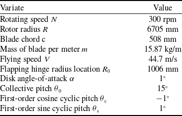
Parameters of the rotor studied by Perdomo are shown in Table 1.
Rotor parameter

Table 1. Long description
A table with two columns and ten rows. The first column is labeled ‘Variate’ and the second column is labeled ‘Value’. The table lists various rotor parameters and their corresponding values. Row 1: Rotating speed N, 300 rpm. Row 2: Rotor radius R, 6705 mm. Row 3: Blade chord c, 508 mm. Row 4: Mass of blade per meter m, 15.87 kg/m. Row 5: Flying speed V, 44.7 m/s. Row 6: Flapping hinge radius location R0, 1006 mm. Row 7: Disk angle-of-attack, 1 degree. Row 8: Collective pitch, 15 degrees. Row 9: First-order cosine cyclic pitch, -1 degree. Row 10: First-order sine cyclic pitch, 1 degree.
Namely, the cyclic pitch is
 $\theta$
= 15° − 1° cos
 $\varphi$
+ 1° sin
 $\varphi$
.
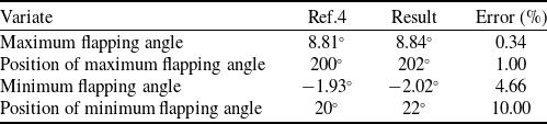
After 50 iteration steps in MATLAB 2023b, the calculation converges, and the results are shown in Table 2 and Figure 6.
Result of flapping angle

Table 2. Long description
A table with four rows and three columns comparing flapping angle variates. The columns are labeled Ref.4, Result, and Error (percent). The rows are labeled Maximum flapping angle, Position of maximum flapping angle, Minimum flapping angle, and Position of minimum flapping angle. Row 1: Ref.4, 8.81; Result, 8.84; Error (percent), 0.34. Row 2: Ref.4, 200; Result, 202; Error (percent), 1.00. Row 3: Ref.4, 1.93; Result, 2.02; Error (percent), 4.66. Row 4: Ref.4, 20; Result, 22; Error (percent), 10.00.
Components of flapping angle

Table 3. Long description
A table with three rows and three columns comparing components of flapping angle. The columns are labeled Variate, Ref.4, Result, and Error (%). The row labels are Constant component, First-order cosine component, and First-order sine component. The values in the table are as follows: Row 1: Constant component, 3.44, 3.41, 0.87 percent. Row 2: First-order cosine component, 4.99, 5.03, 0.80 percent. Row 3: First-order sine component, 1.95, 2.02, 3.59 percent.
The results of this work and those of Perdomo were both transformed using Fourier analysis, and the values of each order component are listed in Table 3.
Result of flapping angle.

When the flying speed increases to 65 m/s, the collective pitch becomes
 $\theta$
0 = 15° and the cyclic pitches become
 $\theta$
c
= 0° and
 $\theta$
s
= 0°. For comparison with the proposed method, a step-by-step iterative approach was adopted, which required solving the differential equations in each iteration. The algorithm operated by computing the flapping angle and aerodynamic moment at 1° azimuth steps, fitting them to a first-order harmonic function and solving the resulting differential equation using MATLAB’s dsolve function (with default settings). The output was then passed to the next iteration.
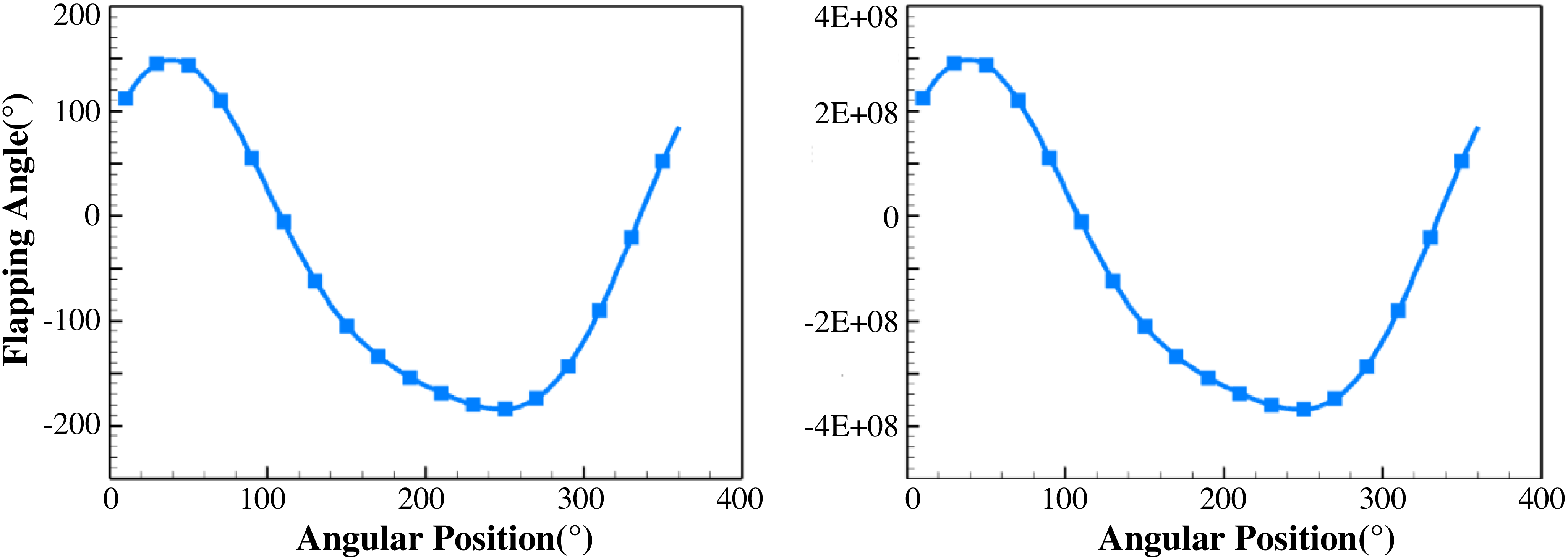
Figure 7 shows the flapping angle obtained by solving the differential equations directly. The maximum value in the second iteration was already larger than 150° in the second iteration and reached 108 degrees in the third iteration, which suggested this method might diverge when dealing with high speed.
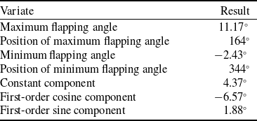
Table 4 and Figure 8 show the results of the flapping angle using the proposed method. After 50 iterations, the result converged. The maximum flapping angle was 11.17°, and the minimum flapping angle was − 2.43°.
Result of flapping angle

Table 4. Long description
A table comparing different variates of flapping angle results. The table has two columns: Variate and Result. It contains seven rows with the following data: Row 1: Maximum flapping angle, 11.17; Row 2: Position of maximum flapping angle, 164 degrees; Row 3: Minimum flapping angle, 2.43; Row 4: Position of minimum flapping angle, 344 degrees; Row 5: Constant component, 4.37; Row 6: First-order cosine component, 6.57; Row 7: First-order sine component, 1.88.
Result of flapping angle, (a) is the 2nd iteration step and (b) is the 3rd iteration step.

4.2 Example for rotor by Yoon
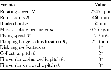
Parameters of the rotor studied by Yoon are shown in Table 5.
Yoon did not present the exact value of the flapping angle. Figure 9 shows the calculated flapping angle curve (red line) and the flapping angle curve presented by Yoon (black line). It can be seen that the two curves are very close to each other.
Rotor parameter

Table 5. Long description
A table listing rotor parameters with 11 rows and 2 columns. The columns are labeled Variate and Value. The table includes the following data: Row 1: Rotating speed N, 2245 rpm; Row 2: Rotor radius R, 460 mm; Row 3: Blade chord c, 50 mm; Row 4: Mass of blade per meter m, 0.25 kg/m; Row 5: Flying speed V, 17.7 m/s; Row 6: Flapping hinge radius location R 0, 25.3 mm; Row 7: Disk angle-of-attack α, 1 degree; Row 8: Collective pitch θ 0, 2 degrees; Row 9: First-order cosine cyclic pitch θ c, 0 degrees; Row 10: First-order sine cyclic pitch θ s, 0 degrees.
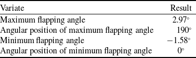
Some calculated parameters are shown in Table 6.
Calculation result

Table 6. Long description
A table displaying calculated parameters for rotor performance. The table has 4 rows and 2 columns. Column headers are Variate and Result. Row 1: Maximum flapping angle, 2.97 degrees. Row 2: Angular position of maximum flapping angle, 190 degrees. Row 3: Minimum flapping angle, -1.58 degrees. Row 4: Angular position of minimum flapping angle, 0 degrees.
4.3 Angular position(°)
It can be seen that the method that compares frequency component amplitudes can calculate flapping angle with satisfactory accuracy when dealing with simulated rotors in the references mentioned above, and it is more robust than methods such as solving differential equations directly when dealing with conditions such as high flying speed.
Flapping angle under a velocity of 65 m/s.

Results of the 2 methods.

5.0 Experiment validation
5.1 Test bed configuration
In order to validate the accuracy of the model further, a helicopter-rotor test bed was built, on which the flapping angle could be measured.
Test bed configuration.

A rotor of 1140 mm in diameter was mounted on the test bed and was driven by a brushless DC motor (the blue component in Figure 10). The rotation speed was measured by a Hall element and could be directly controlled by the user. An angle sensor was used to measure the azimuth angle of the blades.
Real test bed.

Two control modules were embedded in the static structure and the rotating shaft, respectively. The static one received the user’s control command, transmitted the thrust command to the motor, and transmitted the pitching command to the rotating module through a slip ring (the cyan component in Figures 10 and 11). The rotating module then transmitted the pitching command to the servo motors.
A servomotor was installed at the root of each blade (the black cylindrical components in Figure 12) to adjust the blade’s pitch angle. The servo motors rotated following certain cosine and sine functions along the azimuth angle during the shaft rotation. The flapping hinge used roller bearings to ensure that there was almost no flapping damping. An angle sensor (the green cylindrical components in Figure 12) at the location of each flapping hinge measured the flapping angle in real time.
Blade root (a) is the servo motor, and (b) is the flapping angle sensor.

The two different angle sensors are shown in Figure 13. The Pandauto P3015S angular sensor was employed for flapping angle measurement, which had an angular resolution of 0.09° and a response time of 2 ms. A GTKS23836 angular sensor was used to measure the rotational azimuth angle of the rotor, with a response time of 0.2 ms.
Sensors used on the test bed, (a) is the flapping angle sensor, and (b) is the angular-position sensor.

5.2 Test data
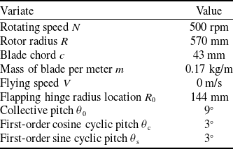
During the test, the rotor operated at a given rotation speed (e.g. 500 RPM) for a few seconds, while the flapping angle sensors measured the flapping angle along the angular position of each blade. Some parameters of the tested rotor and the test condition are shown in Table 7, and the cyclic pitch was
 $\theta$
= 9° + 3°cos
 $\varphi$
+ 3°sin
 $\varphi$
.
Rotor parameter on the test bed

Table 7. Long description
A table titled ‘Rotor parameter on the test bed’ with two columns: Variate and Value. The table has 9 rows, each listing a different parameter and its corresponding value. Row 1: Rotating speed N, 500 rpm. Row 2: Rotor radius R, 570 mm. Row 3: Blade chord c, 43 mm. Row 4: Mass of blade per meter m, 0.17 kg/m. Row 5: Flying speed V, 0 m/s. Row 6: Flapping hinge radius location R0, 144 mm. Row 7: Collective pitch θ0, 9 degrees. Row 8: First-order cosine cyclic pitch θc, 3 degrees. Row 9: First-order sine cyclic pitch θs, 3 degrees.
The calculated and measured flapping angles are shown in Figure 14, and it can be seen that the simulation achieved the theoretical
 $\pi$
/2 phase difference between pitch angle and flapping angle and was in close agreement with the actual measurements.
Test data and calculated results

Table 8. Long description
A table with three rows and four columns comparing calculated results and measured data for rotor parameters. The columns are labeled Variate, Calculated Result, Measured Data, and Error. The row labels and values are as follows: Row 1: Constant component, 6.4 degrees, 6.8 degrees, 0.4 degrees. Row 2: First-order cosine component, -2.4 degrees, -1.9 degrees, 0.5 degrees. Row 3: First-order sine component, 3.5 degrees, 2.8 degrees, 0.7 degrees.
Test data and calculated result of flapping angle.

5.3 Angular position(°)
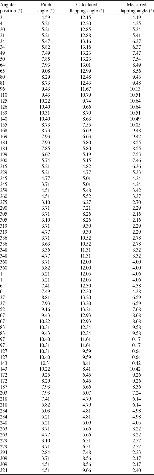
After sine-cosine fitting, the magnitude of different frequency components is shown in Table 8. The detailed angle along the angular position can be found in Appendix A, Table A1.
It can be seen that the method presented in this paper can calculate the flapping angle of helicopter rotors with satisfactory accuracy.
6.0 Conclusions
This article presents a method to calculate the helicopter blade flapping angle and aerodynamic moment variation along the rotation angular position. This method employs a step-by-step iterative algorithm – which assumes a flapping angle, calculates the hub moment using the blade element theory and then solves the flapping dynamic equation again for an updated angle – to address the inherent strong two-way fluid–structure coupling in helicopter blade flapping.
For the specific solution of the flapping dynamic equation, this paper, based on the phase difference between the helicopter blade flapping angle and the aerodynamic force, adopts an algorithm that compares the same-order frequency components of the flapping angle on the left side and the aerodynamic moment on the right side one by one to solve the corresponding coefficients, thereby avoiding solving the differential equation directly.
Validations using both theoretical rotor parameters and actual test data were performed, and the accuracy reached ±0.1° for simulated rotors and ±1° for actual test data. The decrease in accuracy when dealing with the actual rotor was probably due to the measurement error. Experimental and simulation results indicate that acceptable accuracy for engineering applications can be achieved.
This paper is primarily based on the assumption of a specific phase difference between the flapping angle and the aerodynamic excitation force. In theory, the method is mainly suitable for fully articulated rotors with a small hinge offset. However, according to test results, the algorithm can still achieve acceptable accuracy even when the flapping hinge offset is as large as 25%. Subsequently, research can be conducted on applying this algorithm to hingeless rotors that incorporate flapping damping.
Appendix
Measured and calculated flapping angle

Table A1. Long description
The table presents data on angular position, pitch angle, calculated flapping angle, and measured flapping angle. It has 50 rows and 4 columns. The columns are labeled as Angular position (), Pitch angle (), Calculated flapping angle (), and Measured flapping angle (). Each row provides specific values for these parameters. Notable trends or patterns are not explicitly summarized here, but the table allows for detailed comparison of the calculated and measured flapping angles across different angular positions and pitch angles.