





Nomenclature
Abbreviation
- 3D
Three-dimensional
- AI
Artificial intelligence
- AP
Average Precision
- BTK
Information Technologies and Communication Authority (Türkiye)
- CT-ICP
Continuous-Time Iterative Closest Point
- EMC
Electromagnetic compatibility
- EMF
Electromagnetic field
- EMFS
Electromagnetic field strength
- FOV
Field of view
- FPS
Frames per second
- GNSS
Global Navigation Satellite System
- GPS
Global Positioning System
- GSM
Global System for Mobile Communications
- HIRF
High-intensity radiated field
- HOG
Histogram of Oriented Gradients
- ICNIRP
International Commission on Non-Ionizing Radiation Protection
- ICP
Iterative Closest Point
- IoT
Internet of Things
- IoU
Intersection over Union
- LiDAR
Light Detection and Ranging
- mAP
mean Average Precision
- OHS
Occupational health and safety
- OpenCV
Open Source Computer Vision Library
- R-CNN
Region-based Convolutional Neural Network
- RGB
Red--green--blue
- RMS
Root mean square
- ROS
Robot Operating System
- SIFT
Scale-Invariant Feature Transform
- SLAM
Simultaneous localisation and mapping
- SSD
Single Shot MultiBox Detector
- UAV
Unmanned aerial vehicle
- WHO
World Health Organization
- YOLO
You Only Look Once
Symbol
-
 $E$
-
Resultant electric-field magnitude in Equation (1); applicable electric-field limit in Equation (2), V/m
-
$E_x, E_y, E_z$
-
Orthogonal electric-field components, V/m
-
$d$
-
Far-field safety distance in Equation (2); LiDAR line-of-sight range in Equation (13), m
-
$P$
-
Transmitted power, W
-
$G$
-
Antenna gain, dBi
-
$s$
-
Homogeneous projection scale factor
-
$\mathbf{x}$
-
Homogeneous image coordinate
-
$K$
-
Camera intrinsic matrix
-
$R$
-
Rotation matrix in the LiDAR-to-camera extrinsic transformation
-
$T$
-
Translation vector in the LiDAR-to-camera extrinsic transformation
-
$\mathbf{X}$
-
Homogeneous 3D LiDAR point in the camera-projection equations
-
$S^n$
-
Incoming LiDAR scan at scan index
$n$
-
$I^n$
-
Keypoint set extracted from incoming LiDAR scan
$S^n$
-
$M^n$
-
Local sparse-voxel map associated with scan
$n$
-
$\Omega_b,\,\Omega_e$
-
Estimated start and end poses used by the continuous-time scan model
-
$X\in SE(3)^2$
-
CT-ICP optimisation variable representing the start/end-pose pair
-
$F_{\mathrm{ICP}}(X)$
-
Continuous-time ICP objective term
-
$C_{\mathrm{loc}}(X)$
-
Localisation-continuity constraint term
-
$C_{\mathrm{vel}}(X)$
-
Velocity-continuity constraint term
-
$\beta_l,\,\beta_v$
-
Weights applied to the localisation and velocity constraint terms
-
$D_{\mathrm{proj}}$
-
Horizontal projection of the LiDAR slant range, m
-
$\theta$
-
Elevation angle of the LiDAR line of sight relative to the horizontal plane
-
$C=(x_b,y_b)$
-
Estimated horizontal antenna position
-
$P_u=(x_u,y_u,z_u)$
-
Current UAV position
-
$r_h$
-
Horizontal operating radius around the estimated antenna position
-
$\psi_0$
Reference bearing from the antenna to the current UAV position
-
$\Delta\psi$
-
Desired angular offset between measurement waypoints, rad
-
$P_0,\,P_-,\,P_+$
-
Constant-altitude measurement waypoints
-
$z_u$
-
UAV altitude used for the constant-altitude waypoint construction


1.0 Introduction
This study introduces an integrated UAV-based system for measuring electromagnetic field strength (EMFS) around communication infrastructure, including transmitter and receiver stations. The system combines broadband sensing with visual cameras, 3D LiDAR, automated object detection, localisation, point-cloud-based simultaneous localisation and mapping (SLAM), sensor fusion, telemetry and waypoint-based measurement positioning. The demonstrated workflow is intended to extend conventional inspection to elevated and difficult-to-access spatial locations and to support compliance-oriented EMFS assessment. Formal metrological certification and final regulatory compliance decisions remain outside the scope of the present study.
Exposure limits for electromagnetic fields generated by electronic communication devices are regulated in Türkiye by the Information Technologies and Communication Authority (BTK). These national procedures are aligned with international radiofrequency electromagnetic-field exposure guidance, particularly the International Commission on Non-Ionizing Radiation Protection (ICNIRP) guidelines for the 100 kHz–300 GHz frequency range and the public-health framework of the World Health Organization (WHO) for base stations and wireless technologies [1–3]. According to the national measurement procedure, measurements should be performed outside the safety distance and at locations selected with respect to the antenna radiation pattern. Conventional ground- or rooftop-based measurements using electric-field probes may involve restricted access to private properties, occupational safety risks and practical limitations caused by public reactions or unsuitable measurement locations. The UAV-based system proposed in this study addresses these limitations by enabling remote, spatially flexible and height-aware EMFS measurements around Global System for Mobile Communications (GSM) base-station antennas.
The proposed unmanned aerial vehicle (UAV) system illustrated in Figure 1 employs a visual camera, 3D Light Detection and Ranging (LiDAR), global navigation satellite system (GNSS) and barometer sensors to associate antenna detections, range information and field measurements within a common inspection workflow. By enabling measurements at elevated or otherwise difficult-to-access positions, the platform directly reduces the need for personnel access to such locations. Reduced inspection time and cost are plausible operational benefits, although these quantities were not measured comparatively in the present study.
1.1 Related work
Prior UAV-based electromagnetic sensing spans source mapping, geophysical detection and telecommunication-infrastructure monitoring. A University of Michigan patent describes UAV-assisted adaptive mapping of electromagnetic and other hazardous sources [Reference Kearfott and Liu4], while a Saudi Aramco patent addresses drone-based electromagnetic sensing for shallow drilling hazards [Reference Colombo, Turkoglu and McNeice5]. A low-frequency UAV test system with a tethered antenna has also been reported [Reference Chen, Huang, Liu, Zhao and Liu6]. Most directly, Pomarnacki et al. demonstrated UAV-based electromagnetic-radiation measurements around telecommunication towers using a spectrum analyser and automated flight trajectories [Reference Pomarnacki, Brucas, Jacionis and Plonis7]. The present study differs by integrating broadband EMFS acquisition at GSM base stations with antenna-specific visual detection, camera–LiDAR ranging, Continuous-Time Iterative Closest Point (CT-ICP)-supported spatial context, onboard processing and waypoint-based measurement positioning in one inspection workflow.
Developed UAV-based EMFS measurement tracking system.

Figure 1. Long description
A diagram of a UAV-based system for measuring electromagnetic fields around GSM base-station antennas. The diagram shows a base station on the left, connected to a measurements tablet. The tablet interacts with a database, which is connected to both a company and an authorized person through the internet and intranet respectively. The base station information is sent to the database, and the measurements result is sent back to the tablet. The authorized person and the company can access the database through the intranet and internet.
Recent work has increasingly examined UAV-based electromagnetic inspection due to its advantages in hazardous and inaccessible environments. UAV inspection around extra-high-voltage transmission lines has been studied through electric- and magnetic-field safety-distance analysis [Reference Boukabou and Kaabouch8]. In another electromagnetic sensing application, a UAV-based frequency-domain electromagnetic system has been developed for detecting shallow subsurface targets [Reference Li, Xing and Zhang9]. Another important research direction concerns the electromagnetic compatibility (EMC) of UAVs themselves. UAV behaviour under high-intensity radiated field (HIRF) exposure has been analysed through transfer-function models [Reference Ma, Wei and Yuan10]. Commercial UAV immunity near base-station antennas has also been evaluated, with uncontrolled descent reported above 30 V/m [Reference Kubacki, Przesmycki, Bugaj and Laskowski11]. These findings emphasise the need for robust UAV platforms in high-EMFS environments. The present work focuses specifically on GSM base-station antennas and uses broadband EMFS sensing to support spatial field assessment around elevated antenna installations.
UAV–LiDAR systems have been applied to geospatial mapping, agriculture, coastal monitoring, power-line inspection and forestry [Reference Zhou, Gu, Cheng, Yang, Shu and Sun12–Reference Morsdorf, Eck, Zgraggen, Imbach, Schneider and K”ukenbrink19]. Low-cost UAV–LiDAR systems using Livox scanners have also been evaluated against higher-end UAV–LiDAR platforms for forestry applications [Reference Hu, Sun and Su20]. The present work differs by integrating LiDAR perception with EMFS measurement around GSM base-station antennas.
Camera–LiDAR fusion has become important in autonomous driving and mapping because complementary sensing can improve scene association under varying conditions. In the proposed system, visual cameras and 3D LiDAR are combined with SLAM to provide antenna ranging, motion-compensated pose continuity and coherent three-dimensional spatial context for the measurement workflow. The calibration and ranging tests support these functions within the tested conditions, although they do not constitute a full metrological validation. The following summarises relevant work on object detection and SLAM.
1.1.1 Visual object detection
Antenna identification relies on visual-camera imagery. Classical recognition pipelines used handcrafted descriptors such as Histogram of Oriented Gradients (HOG), Scale-Invariant Feature Transform (SIFT), and local quantised patterns [Reference Dalal and Triggs21–Reference Hussain and Triggs23]. Object detection and classification were subsequently advanced through deformable-part models, localisation/classification pipelines, region selection, multiple-kernel methods and cascaded or convex-class classifiers [Reference Felzenszwalb, McAllester and Ramanan24–Reference Cevikalp and Triggs31].
Deep-learning methods subsequently advanced object detection through Region-based Convolutional Neural Network (R-CNN), Fast R-CNN and Faster R-CNN [Reference Girshick, Donahue, Darrell and Malik32–Reference Ren, He, Girshick and Sun J.Faster34]. One-stage detectors, including You Only Look Once (YOLO), YOLOv2, YOLOv3, YOLOv7, Single Shot MultiBox Detector (SSD) and RetinaNet, enabled real-time object detection [Reference Redmon, Divvala, Girshick and Farhadi35–Reference Lin, Goyal, Girshick, He and Dollar40]. Deep learning has also been reviewed in UAV absolute visual localisation studies, highlighting its relevance to UAV perception pipelines [Reference Couturier and Akhloufi41]. The present system employs a customised YOLO model to detect base-station antennas for subsequent 3D localisation.
1.1.2 Point cloud-based SLAM
SLAM techniques estimate platform motion while building a representation of the surrounding environment from LiDAR, camera, radar or fused sensing. LiDAR odometry and mapping have been developed using real-time SLAM architectures and ICP variants based on point-to-line and point-to-plane metrics [Reference Pang, Tan, Li, Li, Ji and Song42–Reference Low44]. LiDAR simulation has also been used to generate point clouds for SLAM evaluation [Reference Sobczak, Filus, Domański and Domańska45]. Multi-sensor calibration, including camera–LiDAR calibration, is an important prerequisite for fusion-based mapping [Reference Lee, Lee and Park46].
Recent studies have increasingly emphasised fusion-based SLAM approaches for improving localisation and mapping performance in UAV applications [Reference Ding, Zhang, Zhou, Yan, Tian and Gu47]. This trend is also evident in recent surveys of UAV and visual SLAM technologies [Reference Wang, Kooistra, Pan, Wang and Valente48, Reference Zhuang, Zhong, Xu, Tian and Yu49]. In this work, CT-ICP was employed to mitigate motion-induced distortions through continuous-time scan registration while maintaining smooth relative pose estimates necessary for consistent three-dimensional reconstruction during flight. Since an independent ground-truth trajectory was not available, no claims regarding absolute localisation accuracy are made. The adopted methodology is consistent with contemporary multi-sensor UAV navigation and mapping frameworks reported in the literature [Reference Khoramshahi, Nezami, Pellikka, Honkavaara, Chen and Habib50, Reference Gupta and Fernando51].
1.2 Contributions
A previous study [Reference Isilak, Durmaz, Salk, Cevikalp, Dutagaci and Girgin52] focused on the initial UAV-based EMFS measurement concept and preliminary experiments. Building on that work, the present study integrates broadband EMFS measurement, YOLO-based antenna detection, camera–LiDAR association, CT-ICP-supported pose and mapping and waypoint-based positioning within a single UAV platform. The field measurements demonstrate that this integrated workflow enables EMFS observations at elevated and spatially flexible positions that are difficult to represent using ground-level sampling alone. The platform is therefore relevant to compliance-oriented inspection and provides a technical basis for future frequency-resolved interference investigation, coverage mapping and more autonomous inspection functions.
2.0 Materials and methods
This study develops methods and software enabling UAVs to detect receiver and transmitter antennas of GSM base stations, perform 3D environmental modelling through visual object detection and LiDAR-based ranging, measure EMFS and transfer the results to the measurement tablet used in current BTK procedures. The integrated camera and LiDAR were used for antenna detection, range association and spatial localisation, whereas the broadband field meter provided the EMFS observations. The following sections explain the motivation and system components.
Measurement tracking system used in conventional EMFS inspection procedures.

2.1 Motivation
BTK-authorized EMFS measurements are based on electric-field strength and/or power-flux-density measurements, depending on the operating conditions and the measurement region. These measurements are transmitted to the BTK Measurement Tracking System (ÖTS), as shown in Figure 2. In near-field conditions, electric- and magnetic-field components may exhibit complex behaviour and may require separate probes, whereas far-field measurements are generally performed using an electric-field probe. When multiple transmitters contribute to the measured field, a broadband EMFS device measures the resultant field strength. If the measured value exceeds the limit defined for a single device, a spectrum analyser and a directional antenna are required to identify the individual contribution of each transmitter [1].
 \begin{equation} E=\sqrt {E_x^2+E_y^2+E_z^2}. \end{equation}
For a three-axis isotropic electric-field probe, the resultant field magnitude is conventionally represented by Equation (1). In the present field dataset, the EMFS output corresponds to the resultant field reading; separate time histories of the individual
 $E_x$
,
 $E_y$
and
 $E_z$
components were not retained.
BTK regulations require measurements at three points around the antenna radiation pattern from accessible areas outside the safety distance (Figure 3). Measurements must be renewed for new stations, antenna adjustments, power changes or technology updates [1]. Practical challenges include restricted rooftop access, public resistance, private property limitations, and occupational health and safety (OHS) risks on tall structures. GPS-based positioning can also be unreliable due to urban density and multipath errors.
Top-down representation of base-station sector directions and regulatory measurement points.

To address these practical limitations, the UAV platform was used to collect measurements from spatial positions outside the safety distance. Figure 4 illustrates nominal regulatory measurement locations (1–3) and examples of practically accessible locations (4–6), which may differ because of access and visibility constraints.
Representative measurement points around a base station positioned on a building.

Under far-field conditions, assuming free-space propagation and using the equivalent isotropically radiated power relation, the safety-distance expression can be written as follows [1]:
 \begin{equation} d=\frac {\sqrt {30 \times P \times 10^{G/10}}}{E}. \end{equation}
Here,
 $d$
is the far-field safety distance in metres,
 $P$
is the transmitted power in watts,
 $G$
is the antenna gain in dBi and is converted to linear scale by
 $10^{G/10}$
, and
 $E$
is the applicable electric-field limit in V/m for the relevant frequency and exposure category. This relation is used only to define the regulatory/geometric safety distance and not to model the measured field distribution.
Under favourable conditions, measurements are acquired from three different positions, as illustrated in Figure 5. To investigate the influence of vertical sampling location at the study site, a preliminary crane-based experiment was performed by maintaining an approximately constant horizontal distance from the antenna while varying the measurement height. As shown in Figure 6, the recorded electric-field intensity increased within the tested height range. This site-specific observation highlights the value of UAV-based measurements for controlled sampling at elevated locations, but it should not be interpreted as evidence of a universally increasing relationship between field intensity and height.
Representative measurement configurations around the antenna safety-distance region.

Figure 5. Long description
Panel 1: A person holding a device and connected to another person with a tether. Panel 2: A person holding a device and standing at a distance. Panel 3: A person holding a device and connected to a structure with a tether. Panel 4: A drone with a tethered antenna positioned within a safety distance region around an antenna.
Variation of electric-field intensity with measurement height in the crane-based preliminary test.

2.2 Proposed system components
The proposed system measures EMFS around GSM base-station antennas using a broadband EMFS sensor mounted on a UAV equipped with a visual camera, LiDAR unit and navigation hardware. Software was developed to detect antennas, estimate UAV pose using camera-LiDAR fusion, perform EMFS measurements and transmit results to the standard regulatory tablet.
The UAV identifies antennas using camera images, associates detections with LiDAR point clouds for 3D range and spatial-context estimation and uses these outputs to support positioning at the required safety-distance offset. EMFS values are then recorded and transferred to the BTK measurement interface. Details on calibration, visual object detection and EMFS measurement are provided in the following sections.
2.2.1 UAV selection and sensor integration
A Narda NBM-550 broadband field meter (Narda Safety Test Solutions GmbH, Pfullingen, Germany) and a spectrum analyser were integrated into the UAV payload. The NBM-550 was used for the broadband electric-field measurements presented in this study. The instrument supports interchangeable isotropic probes, RMS-based field evaluation in V/m, automatic application of probe-specific calibration correction data and a system frequency coverage extending up to 90 GHz depending on the connected probe. The spectrum analyser was included to enable frequency-selective analysis when the contributions of individual transmitters need to be distinguished. Due to the lack of compatible instrument drivers for the Linux-based NVIDIA Jetson/Xavier platform, a Windows-based LattePanda computer was employed for instrument communication and data acquisition (Figure 7). The EMFS probe was mounted with a physical separation from the main onboard electronics to reduce potential interference, as illustrated in Figure 7.
DJI Matrice 600 Pro UAV equipped with the integrated measurement devices and sensors.

Figure 7. Long description
A diagram of a DJI Matrice 600 Pro UAV equipped with various measurement devices and sensors. The UAV includes a camera mounted at the top, a lidar sensor next to the camera, a Jetson Xavier processing unit, an EMF meter, and spectrum analyzers. The camera and lidar are positioned at the top for optimal viewing and scanning. The Jetson Xavier unit is centrally located for processing data. The EMF meter and spectrum analyzers are attached to the sides for measuring electromagnetic fields and spectrum data.
With the addition of these two devices, the total payload increased to approximately 3 kg, leading to the selection of the DJI Matrice 600 Pro UAV as the UAV type. The image taken by the UAV during the measurement process is given in Figure 8.
Real-time UAV-based EMFS measurement process in the field.

2.2.2 Determination of antenna distances at base stations by UAV using camera and LiDAR sensors
Camera and LiDAR sensors were jointly used to detect GSM antennas and compute their distances from the UAV. YOLO-based visual detection localised the antennas in RGB images; however, because images alone do not provide depth information, LiDAR measurements were used for range estimation. For this purpose, the camera and LiDAR were extrinsically calibrated so that pixel coordinates corresponding to antenna detections could be associated with LiDAR points. Distances were then obtained by projecting LiDAR points onto the image plane and matching them with YOLO-identified bounding regions.
Initial measurements were taken directly opposite the antenna. Afterward, the UAV pose was estimated using 3D SLAM, and additional measurements were collected by adjusting the UAV heading by approximately
 $\pm 5^\circ$
relative to the initial orientation. A concise overview of the YOLOv7 detector, camera-LiDAR calibration methodology and SLAM procedure is provided below.
2.2.2.1 YOLOv7 method
YOLO is a single-stage deep-learning object detector that predicts object locations and class probabilities in one network evaluation [Reference Redmon, Divvala, Girshick and Farhadi35]. Different model scales provide an accuracy–speed trade-off. In this study, YOLOv7-Tiny was selected because of its real-time performance on embedded hardware. YOLOv7 introduced architectural and training improvements designed for efficient real-time detection [Reference Wang, Bochkovskiy and Liao38], making the Tiny configuration suitable for onboard UAV deployment.
2.2.2.2 Camera-LiDAR calibration
Camera–LiDAR calibration aligns the two sensor modalities and requires camera intrinsic calibration together with estimation of the rigid LiDAR-to-camera transformation. Classical camera-calibration methods estimate intrinsic parameters such as focal length and lens distortion [Reference Tsai53, Reference Zhang54]. Camera–laser extrinsic calibration can then be solved using planar or line-based geometric constraints [Reference Lee, Lee and Park46, Reference Zhang and Pless55, Reference Zhang, Zhu, Guo, Li and Liu56].
In this study, extrinsic calibration was performed using a custom planar target (Figure 9) printed on a large sheet and moved around the UAV while synchronised camera and LiDAR data were collected. The Velodyne VLP-16 LiDAR (300,000 points/s,
 $360^\circ$
horizontal,
 $30^\circ$
vertical field of view (FOV)) and a 1920
 $\times$
1080 RGB camera were used. OpenCV was employed to detect calibration corners. Camera intrinsics were computed using the flexible camera calibration method [Reference Zhang54], and the LiDAR–camera transformation was obtained using a planar-target extrinsic calibration approach [Reference Zhang and Pless55]. The solvePnP function was further used to estimate the camera pose and refine the transformation matrix [Reference Hartley and Zisserman57].
The projection relationship between 3D LiDAR points and 2D image coordinates is expressed as:
 \begin{equation} s x = K [R \mid T] X, \end{equation}
where
 $s$
is the scale factor,
 $x$
is the homogeneous image coordinate,
 $K$
is the camera intrinsic matrix,
 $[R \mid T]$
denotes the extrinsic parameters and
 $X$
is the 3D homogeneous LiDAR point [Reference Hartley and Zisserman57]. After estimating all parameters, calibration verification tests were conducted.
Calibration target used for camera–LiDAR extrinsic calibration.

Figure 9. Long description
Panel A: A person stands in an office setting holding a rectangular calibration target. The target features a checkered pattern of black and white squares. Colored lines with markers run horizontally across the checkered pattern in red, orange, yellow, green, and light blue. The person is wearing a dark shirt and black-and-white sneakers.
2.2.2.3 Camera-LiDAR calibration verification tests
Calibration verification used an 8
 $\times$
6 chequerboard (square size 0.05 m). The chequerboard corner locations detected in the RGB image provided the image-plane reference, and calibrated LiDAR points were projected onto the same image for comparison. The verification results indicate a mean reprojection discrepancy of approximately 2 pixels and a mean spatial discrepancy of approximately 0.2 m, supporting the practical quality of the camera–LiDAR association used in the field tests.
To assess operational performance, additional tests were performed during UAV flights. YOLOv7-Tiny was executed onboard the Jetson Xavier for real-time antenna detection. Once antennas were identified, LiDAR points falling within the detected pixel regions were extracted, and their median depth value was used for distance estimation.
Because true antenna distances cannot be directly measured during flight, controlled indoor distance-verification experiments were conducted at target distances of 5 m, 10 m, and 20 m. The median LiDAR-derived depth value within the YOLO bounding box was compared with the reference target distance. The observed errors were approximately 5 cm at 5 m, below 7 cm at 10 m and below 25 cm at 20 m. Taken together with the calibration results, these tests support the operational feasibility and practical distance-estimation accuracy of the YOLO–LiDAR association within the tested conditions and at the safety-distance scale considered in this work. Information on the number of repetitions and standard deviations was unavailable, so the results are not presented as a complete metrological uncertainty characterisation. Future work will extend the validation with repeated independent measurements and uncertainty statistics.
2.2.3 3D SLAM
CT-ICP was employed as the LiDAR-based SLAM framework in this study [Reference Dellenbach, Deschaud, Jacquet and Goulette58]. The implementation follows the continuous-time scan registration and sparse-voxel map representation described in the original method. By modelling sensor motion continuously during scan acquisition, CT-ICP mitigates motion-induced distortions and provides smooth relative pose estimates, enabling consistent three-dimensional reconstruction of the environment throughout the UAV measurement process. During operation, keypoints
 $I^n$
are extracted from each incoming LiDAR scan
 $S^n$
and associated with a local sparse-voxel map
 $M^n$
. The scan registration process is driven by the estimated start and end poses,
 $\Omega _b$
and
 $\Omega _e$
, which define a continuous-time motion model over the scan acquisition interval.
The optimisation problem is defined as:
 \begin{equation} \min _{X \in SE(3)^2} F_{ICP}(X) + \beta _l C_{loc}(X) + \beta _v C_{vel}(X), \end{equation}
where the continuous-time ICP term is:
 \begin{equation} F_{ICP}(X) = \frac {1}{|I^n|} \sum _{i \in I^n} \rho (r_i^2[X]), \end{equation}
with
 \begin{equation} r_i[X] = a_i (\,p_i^W[X] - q_i^W) \cdot n_i, \end{equation}
 \begin{equation} p_i^W[X] = R^{\alpha _i}[X] p_i^L + t^{\alpha _i}[X], \end{equation}
 \begin{equation} R^{\alpha _i}[X] = \operatorname {slerp}(R_b, R_e, \alpha _i), \end{equation}
 \begin{equation} t^{\alpha _i}[X] = (1-\alpha _i)t_b + \alpha _i t_e. \end{equation}
The constraints are defined as:
 \begin{equation} C_{loc}(t_b) = \| t_b - t_e^{n-1} \|^2, \end{equation}
 \begin{equation} C_{vel}(t_b, t_e) = \| (t_e - t_b) - (t_e^{n-1} - t_b^{n-1}) \|^2 . \end{equation}
For the present implementation, the weights were set to
 $\beta _l=\beta _v=0.001$
. The optimisation was terminated when the translation update was below 0.1 cm and the rotation update was below 0.01
 $^\circ$
, or after 5 iterations. These values are implementation settings used in this study rather than new CT-ICP algorithmic contributions.
The local map uses sparse voxels for efficient neighbour access. Each voxel stores up to 20 points with
 $\geq$
10 cm spacing. Neighbourhoods for
 $ p_i^W$
are selected from the 27 adjacent voxels. After optimisation, the new scan is added to the map. Voxels far from the latest scan centre are removed.
As a study-specific robustness rule, scans associated with rotations greater than
 $5^\circ$
were rejected and reprocessed using denser sampling and a larger neighbourhood. This rule was introduced to reduce visibly inconsistent registrations during rapid motion and improve the continuity of the reconstructed point cloud in this implementation. Since an independent ground-truth trajectory was not available for validation, no claims regarding absolute localisation accuracy are made, and the resulting reconstructions should be interpreted as providing internally consistent relative pose estimates rather than distortion-free representations of the environment.
2.2.4 EMFS measurements
2.2.4.1 Measurement protocol and data acquisition
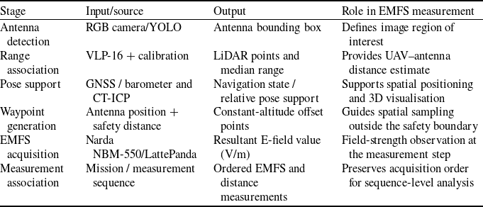
The UAV-based measurement methodology was designed to follow the regulatory measurement geometry at the system level while providing access to elevated sampling locations that are difficult to reach using conventional approaches. Following antenna detection by the YOLO-based vision system, calibrated LiDAR measurements within the detected antenna region were used to estimate the distance to the radiating structure. The UAV was then positioned outside the calculated safety boundary before broadband EMFS measurements were acquired with the Narda NBM-550. The meter uses isotropic RMS field evaluation and automatically applies probe-specific calibration correction data stored in the connected probe. The broadband measurements were used for spatial field assessment rather than as an uncertainty-certified compliance dataset. The ground-based and UAV-based measurements were collected at different spatial locations and were not synchronised; therefore, they are not treated as paired observations. Nevertheless, they provide a useful comparison between field levels observed from accessible ground positions and those measured through flexible aerial sampling. The complete measurement and spatial-association workflow used during the field measurements is summarised in Table 1.
Measurement and spatial-association workflow used in the field measurements

Table 1. Long description
The table compares the performance metrics of V7-Tiny, V7-XLarge, V8-N, and V8-XLarge models on different platforms: TX2, AGX Xavier, and Tesla T4. It has four rows and three columns. The column headers are Platform, V7-Tiny, V7-XLarge, V8-N, and V8-XLarge. The row labels are TX2, AGX Xavier, and Tesla T4. Each cell contains values representing the performance metrics in milliseconds and frames per second (FPS). Row 1: TX2, V7-Tiny: 52.5 ms/19 FPS, V7-XLarge: 409.5 ms/2 FPS, V8-N: Not available, V8-XLarge: Not available. Row 2: AGX Xavier, V7-Tiny: 43.0 ms/23 FPS, V7-XLarge: 82.3 ms/12 FPS, V8-N: Not available, V8-XLarge: Not available. Row 3: Tesla T4, V7-Tiny: 11.1 ms/90 FPS, V7-XLarge: 28.4 ms/35 FPS, V8-N: 10.4 ms/96 FPS, V8-XLarge: 34.6 ms/29 FPS.
2.2.4.2 Calculation of distances to antennas
In this study, the Velodyne VLP-16 LiDAR sensor is used for both distance estimation and environmental mapping. The overall procedure consists of four stages: (i) data acquisition, where the LiDAR collects three-dimensional point cloud measurements; (ii) visualisation, in which the acquired data is displayed in RViz within the Robot Operating System (ROS) framework; (iii) real-time monitoring of the UAV’s surroundings through continuous LiDAR updates; and (iv) distance and position estimation, performed using trigonometric computations applied to the point cloud data.
2.2.4.3 Detection of LiDAR beams using bounding boxes
Distance estimation relies on integrating the Velodyne VLP-16 LiDAR with the YOLOv7 object detection algorithm. This integration enables mapping the 2D image-plane coordinates of detected antennas to their corresponding 3D points in the LiDAR frame. Accurate 2D-3D correspondence requires extrinsic camera-LiDAR calibration to align both sensor coordinate systems. After calibration, distances are computed using trigonometric relationships that incorporate LiDAR range measurements and the camera viewing geometry. The observation angle dynamically varies with the antenna’s position in the camera’s field of view. A key challenge in this stage is ensuring that the LiDAR beams intersect the YOLOv7 bounding box corresponding to the detected antenna, thereby guaranteeing valid 2D-3D point associations.
2.2.4.4 Calibration and mapping process
Camera–LiDAR calibration establishes the geometric relationship between the two sensors. After calibration, each 3D LiDAR point
 $ (X, Y, Z)$
can be projected onto the image plane and associated with the YOLO bounding box of a detected antenna, as expressed in Equation (12):
 \begin{equation} s \begin{bmatrix} x \\ y \\ 1 \\ \end{bmatrix} = K [R \mid T] \begin{bmatrix} X \\ Y \\ Z \\ 1 \\ \end{bmatrix} \end{equation}
The distance to an object is then determined from the calibrated 2D–3D associations and trigonometric calculations based on its three-dimensional position.
When a horizontal stand-off component is required, it can be obtained from Equation (13), where
 $d$
is the LiDAR line-of-sight range and
 $\theta$
is the elevation angle of that line of sight relative to the horizontal plane:
 \begin{equation} D_{\mathrm{proj}} = d \times \cos \theta \end{equation}
This projection is used only when converting the measured slant range to a horizontal geometric component; the primary antenna range used in the camera–LiDAR association is obtained directly from the matched LiDAR points.
The final antenna range estimate is obtained by aggregating LiDAR values projected inside the detected bounding box. During the field tests, the median was used because of its robustness to isolated outliers.
2.2.4.5 UAV movement and positioning
A control routine was used to keep the UAV outside the safety boundary and to generate additional offset measurement points around the detected antenna. The procedure is an offset-waypoint construction, not triangulation from multiple angular observations. Let the estimated horizontal antenna position be
 $C=(x_b,y_b)$
and the current UAV position be
 $P_u=(x_u,y_u,z_u)$
. The horizontal operating radius is
 \begin{equation} \displaystyle r_h=\sqrt {(x_u-x_b)^2+(\,y_u-y_b)^2}, \end{equation}
with
 $r_h$
selected/maintained outside the applicable safety distance. The reference bearing from the antenna to the current UAV position is
 \begin{equation} \displaystyle \psi _0=\operatorname {atan2}\!(y_u-y_b,\,x_u-x_b). \end{equation}
For a desired angular offset
 $\Delta \psi$
(in radians), three constant-altitude measurement waypoints are defined as
 \begin{align} \displaystyle P_0 &= \displaystyle (x_b+r_h\cos\! \psi _0,\;y_b+r_h\sin\! \psi _0,\;z_u), \end{align}
 \begin{align} \displaystyle P_- &= \displaystyle (x_b+r_h\cos\! (\psi _0-\Delta \psi ),\;y_b+r_h\sin\! (\psi _0-\Delta \psi ),\;z_u), \end{align}
 \begin{align} \displaystyle P_+ &= \displaystyle (x_b+r_h\cos\! (\psi _0+\Delta \psi ),\;y_b+r_h\sin\! (\psi _0+\Delta \psi ),\;z_u). \end{align}
This formulation uses the antenna as the centre of rotation, a horizontal radius
 $r_h$
, a single reference bearing
 $\psi _0$
, and a fixed altitude
 $z_u$
for all three waypoints. It removes the previous midpoint ambiguity and preserves the intended constant-altitude sampling geometry. Camera–LiDAR range estimates and ROS sensor streams are used to update the geometric quantities during operation.
The resulting offset-waypoint geometry is illustrated in Figure 10.
Offset-waypoint geometry around the detected antenna.
 $C$
denotes the estimated horizontal antenna position,
 $r_h$
the horizontal operating radius,
 $\psi _0$
the reference bearing and
 $P_0$
,
 $P_-$
and
 $P_+$
the constant-altitude waypoints separated by
 $\Delta \psi$
.

Figure 10. Long description
A diagram illustrating the geometry of a UAV inspection path around a detected antenna. The diagram shows a top view with a circle representing the horizontal operating radius (r_h) centered at a point (C) with coordinates (x_b, y_b). The detected antenna position is marked as P0, and waypoints P+ and P- are located on the circumference of the circle. The reference bearing (ψ_0) and the angular separation (Δψ) between waypoints are indicated. The UAV’s position is denoted as P_u with coordinates (x_u, y_u, z_u), maintained at the same altitude (z_u) as the waypoints.
3.0 Results
We collected images of various GSM antennas from GSM base stations to train our visual object detection algorithms. After calibrating the camera and LiDAR, real-time field measurements were conducted to test the system, and SLAM-based 3D mapping was used to support localisation during measurement. Details of these experimental studies are outlined below.
3.1 Preparation of training data and training of visual object detection algorithms
The dataset used to train the YOLO models was created from approximately 180 minutes of flight video recorded at 14 GSM base stations using Skydio 2, DJI Mavic Air 2 and DJI Matrice 600 Pro UAVs. During data collection, the UAVs performed
 $360^\circ$
flights around each station to capture comprehensive antenna views. Frames were extracted at 3 fps and manually annotated.
Two antenna types were labelled: round MiniLINK receiver antennas and flat rectangular GSM sector antennas. A total of 2,200 frames were annotated. The annotated dataset was divided at the frame level by randomly selecting frames from each recorded flight, resulting in 1,600 training, 400 validation and 200 test images. Representative examples from the annotated dataset are shown in Figure 11.
Representative images from the collected GSM antenna dataset.

The Makesense AI tool (GPLv3) was used for annotation. All evaluated YOLO variants were fine-tuned from pretrained weights on an NVIDIA Tesla T4 GPU using 640
 $\times$
640 input images for 100 epochs with a batch size of 16. The same training, validation and test subsets were used for all models to ensure a consistent performance comparison.
3.2 Testing of trained object detection models
Model performance was evaluated using Precision, Recall, Average Precision (AP) and inference speed. Precision measures the proportion of correct positive detections, while Recall measures the proportion of true positives found. AP provides an integrated measure across confidence thresholds.
Model performance was evaluated using mAP@0.5, computed across the two antenna classes at an IoU threshold of 0.5. As summarised in Table 2, YOLOv8-XLarge achieved the highest mAP@0.5 value (0.904), followed by YOLOv7-XLarge (0.866), YOLOv8-N (0.865) and YOLOv7-Tiny (0.862). Tables 3 and 4 report the corresponding precision and recall results.
Comparison of mAP values for each class

Table 2. Long description
The table compares the performance of different models (YOLOv7-Tiny, YOLOv7-XLarge, YOLOv8-N, YOLOv8-XLarge) in terms of mAP, precision, and recall values for flat and round antenna classes. The table has four rows and five columns. Column headers are Class, V7-Tiny, V7-XLarge, V8-N, V8-XLarge. Row labels are Flat antenna, Round antenna, Average. For mAP values, YOLOv8-XLarge achieved the highest average value of 0.904, followed by YOLOv7-XLarge with 0.866, YOLOv8-N with 0.865, and YOLOv7-Tiny with 0.862. For precision values, YOLOv8-N achieved the highest average value of 0.867, followed by YOLOv8-XLarge with 0.843, YOLOv7-Tiny with 0.842, and YOLOv7-XLarge with 0.802. For recall values, YOLOv7-XLarge achieved the highest average value of 0.879, followed by YOLOv8-XLarge with 0.862, YOLOv7-Tiny with 0.840, and YOLOv8-N with 0.793.
Comparison of precision values for each class

Table 3. Long description
The table compares the mean average precision (mAP) values for different models across two antenna classes. It has four rows and five columns. The columns are labeled Class, V7-Tiny, V7-XLarge, V8-N, and V8-XLarge. The rows are labeled Flat antenna, Round antenna, and Average. Row 1: Flat antenna, V7-Tiny 0.870, V7-XLarge 0.843, V8-N 0.870, V8-XLarge 0.905. Row 2: Round antenna, V7-Tiny 0.855, V7-XLarge 0.889, V8-N 0.860, V8-XLarge 0.903. Row 3: Average, V7-Tiny 0.862, V7-XLarge 0.866, V8-N 0.865, V8-XLarge 0.904. The table shows that YOLOv8-XLarge achieved the highest mAP values for both antenna classes and on average.
Comparison of recall values for each class

Table 4. Long description
The table compares model performance across different classes and models using mAP values. It has four rows and five columns. The columns are labeled Class, V7-Tiny, V7-XLarge, V8-N, and V8-XLarge. The rows are labeled Flat antenna, Round antenna, and Average. Row 1: Class, V7-Tiny, V7-XLarge, V8-N, V8-XLarge. Row 2: Flat antenna, 0.847, 0.794, 0.841, 0.879. Row 3: Round antenna, 0.838, 0.809, 0.893, 0.806. Row 4: Average, 0.842, 0.802, 0.867, 0.843.
In real-time applications, models are executed on embedded computing units integrated into UAVs, specifically the NVIDIA Jetson AGX Xavier and NVIDIA Jetson TX2. The Jetson AGX Xavier, with eight ARMv8.2 CPUs, a 512-core Volta GPU, and 16 GB of LPDDR4x RAM, is suited for high-computation tasks in autonomous vehicles and industrial robots. In contrast, the Jetson TX2, featuring six ARMv8 CPUs, a 256-core Pascal GPU and 8 GB of LPDDR4 RAM, is used in applications such as smart cameras, robotics and UAVs. Runtime performance was evaluated on the NVIDIA Jetson TX2, Jetson AGX Xavier and Tesla T4 platforms using a batch size of 1, as summarised in Table 5. Among the models evaluated on the Jetson platforms, YOLOv7-Tiny provided the most favourable balance between detection performance and computational efficiency, achieving 23 FPS on the AGX Xavier, and was therefore selected for onboard deployment. On the Tesla T4, YOLOv8-N achieved the lowest processing time of 10.4 ms per image. Jetson runtime results were not obtained for the YOLOv8 models.
Inference speed comparison across platforms

Table 5. Long description
A table comparing the performance of different models on various platforms. The table has four rows and four columns. The columns are labeled Class, V7-Tiny, V7-XLarge, V8-N, and V8-XLarge. The rows are labeled Flat antenna, Round antenna, and Average. Row 1: Flat antenna, V7-Tiny 0.840, V7-XLarge 0.891, V8-N 0.848, V8-XLarge 0.890. Row 2: Round antenna, V7-Tiny 0.841, V7-XLarge 0.867, V8-N 0.738, V8-XLarge 0.833. Row 3: Average, V7-Tiny 0.840, V7-XLarge 0.879, V8-N 0.793, V8-XLarge 0.862.
3.3 Real-time EMFS measurements in the field
A pilot base station shown in Figure 12 was selected for field measurements. A ground-level sequence was first recorded outside the 15 m safety distance, and a separate UAV sequence was then collected after the aircraft was repositioned to elevated locations and different viewpoints. The two sequences were not acquired simultaneously at identical coordinates; accordingly, they are not used for an instrument-to-instrument accuracy comparison. They do, however, provide a descriptive field-level contrast between conventional accessible ground sampling and spatially flexible aerial sampling from the same field study.
Field measurement site and the developed UAV-based EMFS measurement system.

Figure 13 shows the operational stand-off distances estimated from the camera–LiDAR association during the field measurements. These estimates document the measurement geometry achieved in operation and complement the controlled 5–20 m ranging verification reported above; the figure itself is not used as an independent accuracy test.
Estimated distance between the UAV and detected antennas using camera–LiDAR data.

Broadband EMFS measurement sequences obtained from UAV and ground-level positions. Sample index represents the acquisition order of the measurements; corresponding per-sample altitude, distance and orientation information was not recorded.

Figure 14 presents the two measurement sequences against sample index. The UAV sequence ranges from approximately 5.5 V/m to above 70 V/m, whereas most of the ground sequence lies near 15–20 V/m after the initial samples. The substantially larger excursion of the UAV sequence is consistent with the platform accessing elevated and laterally displaced regions that are not represented by the fixed ground position. The sample index denotes acquisition order, and per-sample altitude, distance and orientation information was not recorded; therefore, individual peaks cannot be assigned quantitatively to a specific altitude or to exact main-beam alignment. The labels `UAV E-field sequence’ and `Ground E-field sequence’ denote the two broadband measurement sequences.
These observations support the conclusion that fixed ground-level measurements may not adequately represent the full spatial range of broadband field levels around an elevated directional antenna. The UAV-based approach can therefore support more comprehensive exposure assessment and compliance-oriented inspection by extending measurements into otherwise inaccessible spatial regions. Because the present data are broadband and lack frequency-resolved attribution and a complete uncertainty budget, values around and above 70 V/m in the recorded sequence are not, by themselves, interpreted as proof of compliance or non-compliance with a specific exposure limit.
3.3.1 UAV operation in the electromagnetic environment
The measurement flights were successfully completed while the platform operated in the electromagnetic environment encountered during the field measurements, demonstrating practical operability under those test conditions. The study was not designed as a formal electromagnetic-immunity qualification test. The broadband probe was mounted physically away from the main computing and power-electronics assemblies as visible in Figure 7. Accordingly, successful field operation should not be interpreted as a certified immunity limit, and controlled electromagnetic-compatibility testing remains necessary for qualification in high-field regions.
4.0 Discussion
This study developed and field-tested an integrated UAV platform for broadband EMFS assessment around GSM base-station antennas. The demonstrated functions include automated visual antenna detection, camera–LiDAR range association, CT-ICP-supported pose/mapping, waypoint construction outside the safety distance and broadband field acquisition. The principal demonstrated benefit is the ability to sample elevated and spatially flexible locations that conventional accessible ground measurements cannot represent directly. The work therefore demonstrates a practical inspection-oriented workflow, while formal metrological certification and final regulatory compliance decisions require additional controlled validation.
Relative to previous UAV-based electromagnetic sensing and inspection studies, including electromagnetic safety-distance analysis, subsurface sensing and UAV-based telecommunication-tower radiation monitoring [Reference Pomarnacki, Brucas, Jacionis and Plonis7–Reference Li, Xing and Zhang9], the present work focuses on GSM base-station antennas and integrates broadband EMFS acquisition with antenna-specific visual detection, LiDAR-based distance estimation, SLAM-supported spatial context and measurement positioning in a single UAV workflow. This integration and its extended validation constitute the principal journal-level contribution rather than a claim of a new metrological standard.
The results demonstrate the value of UAV-assisted spatial EMFS sampling for extending inspection coverage around elevated antennas and indicate that fixed ground measurements may miss substantial spatial variation. The camera–LiDAR tests also support practical ranging accuracy within the tested distances. Quantitative claims regarding cost reduction or inspection-time reduction require dedicated comparative studies. The demonstrated sensing and localisation architecture also provide a direct technical basis for frequency-resolved interference investigation, service-quality assessment, coverage-map generation, localisation of unauthorised emissions and AI/IoT-assisted monitoring. These functions are considered extension capabilities of the platform and require dedicated task-specific validation before operational deployment.
This study has several limitations. The present study covers a limited set of base-station conditions. The present analysis does not include serial-specific probe calibration-certificate details or the exact dwell/averaging settings; transmitter operating states were not tracked for each sample. The exact probe-to-electronics separation was not measured, and no dedicated telemetry-based anomaly or onboard self-interference test was performed. Camera–LiDAR verification was limited, the object-detection evaluation was based on a frame-level random split, and no independent SLAM ground truth was available. The broadband EMFS data do not provide frequency-resolved contributions or a complete metrological uncertainty budget. Future work should therefore include repeated spatial measurements, frequency-resolved acquisition, uncertainty budgets, station-level detector evaluation, independent SLAM validation and controlled electromagnetic-compatibility testing.
5.0 Conclusion
This study demonstrated an integrated UAV-based workflow that combines broadband EMFS acquisition, visual GSM-antenna detection, camera–LiDAR range association, spatial positioning and CT-ICP-supported 3D mapping. The field measurements showed substantially greater variation in the UAV measurement sequence than in the accessible ground sequence, supporting the use of aerial sampling to reveal spatial field variations around elevated directional antennas that may not be represented by fixed ground measurements. The ranging experiments and embedded YOLO results further demonstrate the practical feasibility of the integrated perception and measurement workflow. Although the present broadband dataset is not sufficient for a formal frequency-resolved compliance decision or a complete uncertainty-certified metrological assessment, the platform provides a practical technical basis for three-dimensional exposure assessment and compliance-oriented regulatory inspection.
Data availability
The data supporting the findings of this study are available from the corresponding author upon reasonable request.
Author contributions
Cemal Isilak: Methodology, Investigation, Data curation, Visualisation, Writing – Original Draft. Hakan Cevikalp: Conceptualisation, Methodology, Formal analysis, Writing – Review and Editing, Supervision. Helin Dutagaci: Methodology, Formal analysis. Yusuf Salk: Software, Validation. Alperen Enes Bayar: Software, Validation. Tufan Girgin: Funding acquisition, Resources, Supervision.
Financial support
This work was supported by the Scientific and Technological Research Council of Turkey (TÜBİTAK) under grant number EEEAG-121E587.
Competing interest
The authors declare that they have no known competing financial interests or personal relationships that could have appeared to influence the work reported in this paper.
AI usage disclosure
The authors confirm that all scientific content, including the conceptual framework, methodology, data analysis, experimental results and conclusions, was created by the authors. An AI-assisted language tool was used solely for linguistic editing and clarity improvement and did not contribute to the study design, interpretation of findings or generation of research data.




 C
 rh
 ψ0
 P0
 P−
 P+
 Δψ






 Open access

