

1.0 INTRODUCTION
In space, structures encounter various severe environments, including severe thermal conditions. When the Engineering Test Satellite-VIII (ETS-VIII) entered the Earth's shadow, the difference in the temperature between day time and night time was approximately 200°C(Reference Satoh, Fujino and Orikasa1,Reference Satoh, Orikasa, Fujino, Kawasaki, Yamamoto, Miura and Taira2) , as shown in Fig. 1. During this eclipse time, the signal level of a radio wave from the Large Deployable Reflector (LDR) mounted on the ETS-VIII was observed to change(Reference Satoh, Fujino, Orikasa, Kohata, Usui and Yamasa3). It was calculated(Reference Fujino, Satoh and Orikasa4) that this phenomenon led to a 60- to 100-km transition of the footprint of the communication beam on the surface of the Earth. Also, it was confirmed that the transition was caused by some thermal deformations of the LDR(Reference Satoh, Fujino and Orikasa1-Reference Usui, Wakita, Kondo, Thanh, Matsui and Isobe6). The deformed value at the midpoint of the LDR was calculated as approximately 5mm when the temperature decreased(Reference Usui, Wakita, Kondo, Thanh, Matsui and Isobe6), which could lead to a 60km transition of the footprint. Nevertheless, it was not a critical issue for the ETS-VIII because the communication beam from the LDR tended to spread over a wide range. However, it may affect the performance of such satellites in the future where highly accurate pinpoint communication beams are expected to be required.
Temperature of the LDR during earth eclipse (©JAXA).

In this paper, a finite element model of the LDR was constructed and a thermal deformation analysis was performed to investigate the behaviour of the LDR during thermal transition. Furthermore, a means to mechanically suppress the thermal deformation was sought by focusing on the internal force generated by the spring used to deploy the antenna and by optimizing the coefficient of thermal expansion of the constituent members.
2.0 NUMERICAL MODEL OF THE LDR
In 2006, the Japan Aerospace Exploration Agency (JAXA) launched the ETS-VIII into a geostationary satellite orbit. Figure 2 shows a general sketch of the ETS-VIII. There are two LDRs, which are the largest antennas mounted on the satellite. Each LDR is as large as a tennis court. This parabolic antenna consists of 14 hexagonal modules and is highly extendable because these modules are all identical and connected with pin joints to reduce mechanical interaction.
ETS-VIII launched in 2006 (©JAXA).

In this study, a 14-module model of the LDR was constructed for analysis. Figure 3 shows the 14-module model and the structural connections of the model. Every module is connected with titanium alloy truss members. These truss members are indicated in grey colour as seen in Fig. 3. In addition, the boom extended from the satellite body is rigidly fixed to Modules 7 and 8. Therefore, rigid joints are implemented in the top and bottom nodes of longitudinal members in Modules 7 and 8 for the 14-module model. Figure 4 shows the allocation sketch of the 14 modules.
14-module model for analysis and the structural connections of the model.

Allocation sketch of the modules.

Figure 5 shows an overview of one module. The LDR consists of CFRP tubes and titanium alloy joints. Figure 6 shows a structural drawing of the automatic open umbrella mechanism in the module. The mechanism is used to deploy the antenna and is installed at the centre axis member of every module. It consists of one spring and six link rod members. The designed residual force of the spring after completion of antenna deployment is 233N.
Overview of one module (©JAXA).

Structural drawing of a deployable mechanism (©JAXA).

The automatic open umbrella mechanism is introduced into the numerical model as shown in Fig. 7. The spring element in the figure is a rahmen element with only its bottom-side node connected to the centre axis member. The upper-side node is connected only to the link rod elements. In these simulations, a spring force was applied to the upper-side and bottom-side nodes of the spring element. Consequently, an internal force is transmitted through the link rod element to the diagonal member. The diagonal member consists of four elements: two elements at the both ends are truss elements and other two in between are rahmen elements. The members beside the diagonal member are all modelled with a single truss element.
Modelling of an automatic open umbrella mechanism.

3.0 THERMAL EXPANSION PROPERTIES OF CONSTITUENT MEMBERS
3.1 Combined coefficient of thermal expansion
The combined Coefficient of Thermal Expansion (CTE) was calculated from the constituent ratio of CFRP and titanium alloy components, as shown in the following equation.
 $$\begin{equation}
{\alpha _C} = \frac{{{l_{{\rm{CFRP}}}}}}{L} \times {\alpha _{{\rm{CFRP}}}} + \frac{{{l_{{\rm{Titanium}}}}}}{L} \times {\alpha _{{\rm{Titanium}}}}
\end{equation}$$
where L is the total length of each member, l CFRP is the length of a CFRP member, α CFRP is the CTE of CFRP, l Titanium is the length of a titanium alloy joint, and α Titanium is the CTE of titanium alloy. In the analyses, thermal deformation of titanium alloy was considered by applying Equation (1), while the stiffness of titanium alloy joints was not taken into account in the modelling.
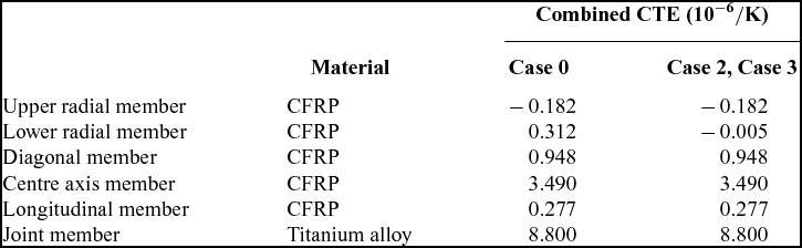
Table 1 shows the dimensions and material properties of the constituent members. The combined CTEs vary because of differences in the fibre orientation angle of each member and in the ratio of titanium alloy components to the total length of the member. Moreover, the upper radial members expand, whereas other members shrink as the temperature decreases. This indicates that the structure of the LDR is expected to have complex behaviour during the temperature transition.
Dimensions and material properties of constituent members

3.2 Thermal strain
The thermal expansion is considered using the following equation, which expresses the relation between the temperature of an object and the thermal strain:
 $$\begin{equation}
\Delta {\varepsilon _T}\ = \ \alpha \Delta T\ ,
\end{equation}$$
where Δε T is the thermal strain increment, α is the coefficient of thermal expansion, and ΔT is the temperature increment. The relation between the mechanical strain and the thermal strain can be expressed as the following equation:
 $$\begin{equation}
{\varepsilon _m}\ = \ \varepsilon \ - \ {\varepsilon _T}{\rm{\ }},
\end{equation}$$
where εm is the mechanical strain, ε is the total strain and εT is the thermal strain. These relations were implemented in a finite element code based on Bernoulli-Euler beam elements and several thermal deformation analyses were conducted.
4.0 NUMERICAL CONDITIONS
The thermal history for the analysis was given as follows; the temperature was gradually increased step by step from 0°C to 50°C with increments of 1°C and was held constantly at the maximum temperature. Then the actual thermal history detected on the ETS-VIII, as shown in Fig. 8, was applied as an input for the analysis. The displacement evaluation point was defined at the centre and peripheral side of the upper radial member of each module. The spring force was also gradually increased step-by-step from 1 to 233N along with the temperature transition in the first phase, as shown in Fig. 9 (areas A–D are explained in Fig. 13). Then, thermal deformation analyses were carried out with and without controlling the spring force.
Applied thermal history.

Applied spring force histories.

The following four cases of analyses were carried out.
-
• Case 0: original case, without any means of suppression (aims to confirm how the thermal deformation occurred in the 14-module model)
Thermal deformation suppressed using the following means:
-
• Case 1: control spring forces uniformly in all modules
-
• Case 2: adjust the combined CTE of the structural members
-
• Case 3: adjust the combined CTE of the structural members and by then control spring forces differently in each module depending on the distances from the constraint point
5.0 THERMAL DEFORMATION ANALYSIS
Case 0
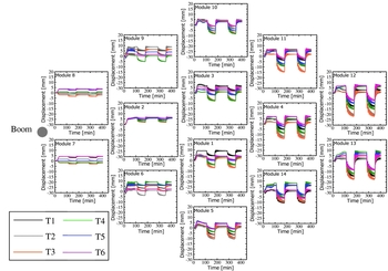
According to the thermal deformation analysis of the original model without any means of suppression, displacements occurred in the direction normal to the reflector surface during thermal transition, as shown in Figs 10 and 11. As shown in Table 1 and Fig. 12(a), these displacements occurred due to the combined CTE of the diagonal member; the combined CTE was three times greater than that of the lower radial member, which helped the member shrink. Furthermore, the upper radial member, with a negative CTE value, expanded when the temperature decreased. Therefore, the displacements occurred in a downward direction. A position further from the constraint point resulted in a greater centre side deformation due to the accumulation of displacements. In the farthest module, the displacements were approximately 20mm. Moreover, the midpoint of the LDR was confirmed to deform by approximately 5mm, which explains the phenomena actually observed on the ETS-VIII.
Displacements occurred in a direction normal to the reflector surface on the centre side of the upper radial member in Case 0.

Displacements occurred in a direction normal to the reflector surface on the peripheral side of the upper radial member in Case 0.
Schematic diagram of thermal deformation due to a decrease in temperature.

Case 1
As a result of controlling spring forces uniformly in all modules as shown in Fig. 9(b), the centre side of the upper radial member was suppressed successfully; however, this resulted in no suppression of the peripheral side of the upper radial member. The mechanism explaining this phenomenon is as follows. As shown in Fig. 12(b), the compression force generated at the diagonal member was reduced and the centre side of the upper radial member was lifted. However, the upper radial member remained stretched while the other members such as the lower radial member and diagonal member shrank due to thermal expansion; consequently, the peripheral sides deformed in the downward direction.
Furthermore, this result clearly indicates that the thermal deformation could be suppressed by distributing different spring forces in four areas depending on the distances from the constraint point, as shown in Fig. 13. Therefore, it is attempted to suppress the thermal deformation, in Case 3, by controlling spring forces differently in each area.
Schematic diagram of the partitions used to control different spring forces.

Case 2
The thermal deformation that occurred in the peripheral sides of upper radial member could not be sufficiently suppressed by distributing different spring forces alone. Therefore, it was suppressed by adjusting the combined CTE of the structural members. In particular, the combined CTEs of the upper and the lower radial member, which have CTE values with opposite signs, were focused to produce maximum suppression effects with a minimum change. In other words, there is a possibility that the thermal deformation can be suppressed by an optimal combination of combined CTEs. On the other hand, the largest inner force is distributed in the diagonal member, which indicates that the diagonal member is presumed to be important for stabilizing the antenna shape. In these circumstances, the combined CTE value of the diagonal member was kept unchanged and some parametric studies were carried out by only changing the combined CTE of the lower radial member to find the optimized combination. The obtained combination is shown in Table 2. As a result, this method resulted in some suppression effects at the peripheral side of the upper radial member. The suppression at centre side is mainly a result of the accumulation of the peripheral side suppression, while in each module, the centre side is barely suppressed by this method, as shown in Figs 14 and 15.
Optimal combination of the combined CTE
Suppression effect at the centre side of the upper radial member in Case 2.

Suppression effect at the peripheral side of the upper radial member in Case 2.

Case 3
Based on the results of Case 1 and Case 2, these thermal deformations were suppressed more effectively in Case 3 by adjusting the combined CTE of the structural members and by then controlling spring forces differently in four areas. As seen in Figs 16 and 17, the thermal deformations are almost suppressed not only at the centre side of the upper radial member but also at the peripheral sides. The effect can be clearly seen in the obtained displacements, as shown in Table 3. The displacements in Case 3 were drastically reduced in all areas compared with the original case (Case 0). In particular, the average maximum displacements were decreased from approximately 5mm (in Case 0) to 0.5mm (in Case 3) at Modules 1 and 3 located at the centre of the LDR, where the electric field strength became the highest. These results indicate that the transition of the footprint of the communication beam on the surface of the earth can be reduced from a range of 60–100km to a range of 5–10km.
Displacements occurred in direction normal to the reflector surface on the centre side of the upper radial member in Case 3.

Displacements occurred in a direction normal to the reflector surface on the peripheral side of the upper radial member in Case 3.

Displacements obtained for each module in each case

6.0 CONCLUSIONS
A finite element model of the LDR was constructed, and a thermal deformation analysis was performed to investigate the deformation behaviour of the LDR during thermal transition. The displacements occurred in the direction normal to the reflector surface during thermal transition. Moreover, the midpoint of the LDR was confirmed to deform by approximately 5mm, which explains the phenomena actually observed on the ETS-VIII.
Furthermore, a means to mechanically suppress the thermal deformation was sought out by adjusting the CTE of the structural members and by then controlling spring forces differently in four areas. As a consequence, the thermal deformations at every apex that support the antenna reflector were all suppressed at a high correction rate. These results indicate that the transition of the footprint of the communication beam on the surface of the earth can be reduced from a range of 60-100km to a range of 5-10km.



