




No CrossRef data available.
Constructing design methodologies using multiagent systems
Published online by Cambridge University Press: 08 April 2005
Abstract
An innovative approach has been developed for discovering better design methodologies that is based on simulating the design process using a multiagent system that mimics the behavior of a design team. The system implements a knowledge-based model of design in which highly specialized knowledge from expert sources is applied to synthesize a design. The agents activate the pieces of design knowledge when they become applicable. The use of knowledge by agents is recorded by tracing the steps that the agents have taken during a design project. Many traces are generated by solving a large number of design projects that differ in their requirements. A set of design methodologies is constructed by using inductive learning techniques to generalize the traces generated. These methodologies then can be used to guide human design teams through future design projects.
Keywords
Information
- Type
- Research Article
- Information
- Copyright
- © 2004 Cambridge University Press
1. INTRODUCTION
This research is about the multidisciplinary design of engineered systems. Examples of multidisciplinary designs are aircraft, automobiles, robots, and buildings. This work extends the concept of analysis by simulation to the area of engineering design research. Analyzing the behavior of physical systems in engineering applications by computer simulation has been a powerful tool in engineering that has resulted in reducing costs and time in comparison to physical prototyping and experimentation.
In this work, the same concept is applied to analyzing the design process instead of the design product. A computational model, in the form of a knowledge-based multiagent system (MAS), simulates the design process. By simulating under different conditions, and examining the performance, detailed understanding of the design process is gained. Similar to simulations of physical systems, the computational model of the design process is a simplified one in which the design activities that are usually carried out by humans are performed by software agents in a slightly simplified manner. We have developed these ideas using the multidisciplinary domain of robot arm design.
1.1. Motivation
The goal of this research is to develop a systematic approach for constructing design methodologies. The needs and motivations for such a systematic approach are the following:
- Need for continuous improvement. To succeed in today's global, competitive market, companies need continuous design process improvements. These improvements should result in expending fewer resources on the design process while achieving better quality and more environmentally friendly products.
- Need for rapid incorporation of new technologies. New technologies (e.g., new materials, manufacturing processes, etc.) are emerging increasingly quickly. They not only improve product quality but they also provide better ways to conduct the design process. We need to incorporate new technologies and methods into design methodologies as quickly as they appear.
- Need for integration. Integration of multiple disciplines in design is a means to enhance the quality of the design, reduce the cost, reduce time to market, and incorporate environmental considerations into the product design. Integration reduces process failures by facilitating information sharing, thus saving resources. Integration also provides collaboration between different participants, enhancing the quality of the design.
- Need for design assistant tools. Design assistant tools are needed that can help designers understand the big picture. Improvements in individual disciplines alone are not sufficient to improve products and processes. To achieve higher quality, we need system-oriented, holistic, multidisciplinary approaches to the design of engineered systems that consume fewer resources (NSF, 1996). Therefore, design research must develop new design methodologies and tools.
- Need for concurrency in design. Concurrent decision making is an important component of design methodology (Badhrinath & Jagannatha Rao, 1996). A concurrent strategy, in contrast to sequential, carries out some of the problem-solving activities in parallel that, as a result, speeds up the design process.
- Recent advances in artificial intelligence (AI) in design. The AI theories and techniques used in this paper (multiagent design systems in particular) provide an opportunity to build superior design methodologies. AI theories and techniques enable engineering design researchers to take advantage of powerful computational techniques.
1.2. Problem
The problem is the following:
There are no systematic approaches to building design methodologies for integrating different disciplines in multidisciplinary design so that they collaborate to contribute to the common goals of the design and also share resources.
The current approaches for improving design processes are mostly based on intuitive observations followed by incremental changes to the existing methodologies. Current multidisciplinary design practices are based on ad hoc strategies for handling the complexities that multiple points of view introduce. They solve the problem of complexity at the expense of giving up the potential advantages of diversity among the disciplines involved. The common methodologies for multidisciplinary design tend to be sequential, which lead to compromising between different disciplines rather than collaborating between them. These methodologies do not use a systematic, holistic approach to the problem of multidisciplinary design, and thus they are not as efficient and effective as they could be.
One aspect of the problem that makes a systematic approach very useful is that design knowledge is constantly evolving. “Designers not only must cope with a complex task, but they must track the evolution of a domain. In this situation, designers determine whether new knowledge is related to the body of existing knowledge, or whether the new knowledge reflects a more fundamental change in technology” (Reich & Fenves, 1991).
Another aspect of the problem in favor of a systematic and automated approach is that the number of specialists is increasing, while the number of generalists, capable of doing system integration, is decreasing. At the same time, the knowledge burden on the designer keeps increasing as more materials and more options become available (NSF, 1996).
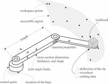
For our research we have chosen the design of robots as the test domain. The type of robot we consider is a planar robot with revolute joints and 2 degrees of freedom (2-DOF) as shown in Figure 1. Reducing the number of DOFs to 2 reduces the computational effort needed. However, the complexity of interactions between multiple disciplines is preserved in a 2-DOF robot. As a result, the design methodologies that integrate disciplines for a 2-DOF robot can provide useful guidelines to integrate disciplines in robots with higher DOFs.

The design parameters of a 2-DOF planar robot.
1.3. Approach
We propose a new approach based on simulating the design process using an MAS that mimics the behavior of a design team. The MAS implements a knowledge-based model of design in which highly specialized knowledge from expert sources are applied to synthesize a design (Lander, 1997). The MAS activates the pieces of design knowledge when they become applicable. The use of knowledge by agents is recorded by tracing the steps that the agents have taken during a design project.
Many traces are automatically generated by solving a large number of design projects that differ in their requirements. A set of design methodologies is constructed by using inductive learning techniques to generalize the traces generated. The methodologies constructed then can be used to guide human design teams through future design projects. In the current stage of this work the process of constructing the design methodologies is not yet fully automated.
The recorded traces of the agent activations (i.e., knowledge use) during the design process consist of orderly patterns of different design tasks that have led to the solution. Some candidate design methodologies are extracted by generalizing the patterns using clustering and inductive learning techniques. Some of these candidates will be reinforced by solving more examples and accepted as design methodologies for that particular class of problems.
2. BACKGROUND
2.1. Design methodology
A design methodology is a scheme for organizing reasoning steps and domain knowledge to construct a solution (Dasgupta, 1989). It provides both a conceptual framework for organizing design knowledge and a strategy for applying that knowledge (Sobolewski, 1996).
Design methodology is different from the design itself. Design is primarily concerned with the question of “what to design” to satisfy some specified need. Design methodology, however, is primarily concerned with the question of “how to design.” Good methodologies allow us to better model, teach, and aid or automate the finding of solutions to what to design. The ability to systematically construct design methodologies facilitates the evolution of design from an art to a science (Kannapan & Marshek, 1992).
A design methodology for integrating multiple disciplines provides knowledge for the following:
- how to evaluate partial designs from all participants' points of view,
- what should be done at each step of the process considering proposals from all participants,
- common representation schemes for design knowledge,
- common communication mechanisms for interactions,
- how to facilitate design knowledge sharing among participants,
- a cooperative strategy among participants,
- how to conduct multiple tasks in the design process concurrently, and
- comprehensive mechanisms for conflict discovery and resolution.
A better design methodology has the following properties (Shakeri, 1998):
- takes less time, causes fewer failures;
- produces better designs (better quality, simpler designs);
- works for a wider range of design requirements;
- integrates different disciplines;
- conducts design in a concurrent fashion;
- consumes less resources: time, money, expertise; and
- requires less information.
2.2. Knowledge-based design
In this research a knowledge-based model of design is used to build a system that simulates the design process. The system activates design methods when they become applicable, uses small design methods, facilitates information sharing, implements control techniques for promoting collaboration, and gives more priority to design tasks that lead to fewer possible conflicts.
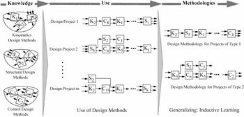
Figure 2 shows how our proposal works for our test domain, the design of a robot arm. There are three different disciplines (i.e., kinematics, structure, and controls) involved in the design process. Design methods from each discipline are broken up into smaller pieces, called “approaches,” such that each one of them has its own inputs, outputs, and constraints. Approaches may make a small number of design decisions, perhaps only one.

The knowledge-based approach to generating design methodologies.
A design project in Figure 3 is a design problem that differs from other problems in its requirements and constraints. As a result, design approaches that become applicable during the design process might be different for different projects. However, as we will see later in this paper, there will be some similar design approach activation patterns for different projects. In this paper a sequence of design approach activations is called a trace.

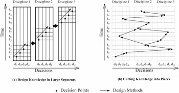
Integration by breaking up the knowledge into smaller segments.
The similar activation patterns are extracted and related to the group of projects that later on will be categorized. To reinforce and further develop the similar patterns into general methodologies, the system solves many examples by perturbing the design requirements within the given range. In this process some of the candidate methodologies developed will be strengthened while some will be weakened and dropped from further development. At the end, there will be a finite number of design methodologies for different types of design problems.
2.3. Strategies for a knowledge-based design system
The following sections describe the main problem-solving strategies followed to produce design methodologies using a knowledge-based approach.
- Small design knowledge. To integrate different disciplines, one main strategy is to cut the big segments of design knowledge accumulated in different disciplines into pieces, breaking design methods into smaller methods called approaches. The resulting smaller design methods means fewer decisions made in each method, shorter time spent in a method, and less information produced as a result of executing that method. Smaller design methods (i.e., the approaches) are simpler and consume less resources (Shakeri, 1998). Decomposition of the design knowledge is a knowledge intensive process; that is, it needs an extensive amount of domain knowledge. Figure 3 demonstrates how approaches reduce time for backtracking and at the same time increase the possibility of parallel decision making.
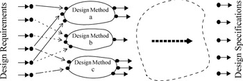
- Opportunistic problem solving. “The key idea is that decisions are made as required and if possible. It moves the attention opportunistically between subproblems and avoids overspecifying local decisions” (Huang & Brandon, 1993). Figure 4 shows the concept of an opportunistic strategy in design. Initial design requirements provide the required inputs so that some of the design methods can be executed and can provide more information. Other approaches get the opportunity to run after the first round of approaches provide input for them. This process continues until the design is complete. Of course, the process will not be this straightforward, because: with the same available information there may be many applicable design methods that could run or there may be none; some of the information produced by the design approaches may violate some of the constraints; the same information produced by more than one design approach may cause conflict; and there may be situations in which the design approaches get stuck in a loop by providing no new information.
- Cooperative problem solving. A cooperative strategy provides mechanisms by which different participants adopt the same goals. Implementation of this strategy in a multidisciplinary design process results in favoring the common goals of the design over local goals (Klein, 1991). As a result of such a strategy, different disciplines use their diverse resources in the same direction. This strategy is implemented in the control mechanism of the design process by strictly giving priority to the common goals of the design and preventing individual designers to impose their local objectives on the rest of the system.
- Least commitment. Least commitment means deferring the decisions that constrain future choices for as long as possible (Jackson, 1990, p. 252). The least commitment strategy is suitable for multidisciplinary situations in which there is strong coupling between subproblems. The strategy is implemented in the design process by giving priority to the design methods that use the least information (i.e., use fewer inputs) to produce the most new information (i.e., not producing information that already exists). The chance of using incomplete, arbitrary, or less reliable information is lower for methods that use the least information. This strategy, too, is implemented in the control mechanism of the design process.
- Inductive learning. “Learning is the improvement of performance in some environment through the acquisition of knowledge resulting from experience in that environment” (Langley, 1996, p. 5). An inductive learning strategy is adopted to develop categories of design methodologies that are specialized in collaboration and sharing of resources. Inductive learning learns from examples. The form of inductive learning used in this work is descriptive generalization. “In descriptive generalization, one is given a set of instances which belong to a particular class, and the task is to derive the most parsimonious description which applies to each member of that class” (Jackson, 1990, p. 433). Descriptive generalization uses examples of design traces and produce classes of design methodologies.
- Means–ends analysis (MEA). This is a general search mechanism. In MEA, each operation should reduce the difference between the current state and the goal state (Jackson, 1990, p. 68). MEA is implemented by choosing design methods that, compared to other methods, push the current state closer to the final state.
- Concurrency. A concurrent strategy carries out some of the problem-solving activities in parallel. Concurrent design is the main theme of the well-established concurrent engineering field. In a concurrent design process, design knowledge is accumulated from all design participants during the design process (Brown & Douglas, 1993).

The opportunistic strategy in activating design methods.
2.4. MAS
The multiagent paradigm captures the concept of deep, modular expertise that is at the heart of knowledge-based design (Lander, 1997). Wooldridge (1997) defines an agent as a self-contained problem-solving system capable of autonomous, reactive, proactive, social behavior. Agents are a powerful abstraction tool for managing the complexity of software systems. An MAS is composed of multiple interacting agents, where each agent is a coarse-grained computational system. In this research agents are used as an abstraction tool for conceptualizing, designing, and implementing the knowledge-based design approach.
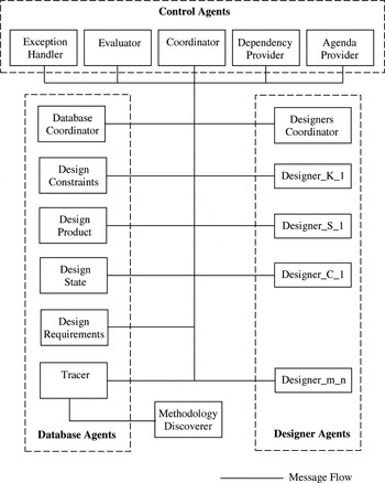
A Java-based computer program called Robot Designer (RD) has been implemented for the design of a 2-DOF planar robot arm. The architecture of the system is shown in Figure 5. There are three different types of agents: control agents, design agents, and database agents.

The architecture of the multiagent design system.
The designer agents contain the knowledge for designing a 2-DOF robot. In Figure 5, each designer m_n agent is responsible for a specific design approach n in discipline m (K stands for kinematics, S for structural, and C for control design of a robot arm). A coordinator agent decides which one of the designer agents can act at various stages of the design process.
The control agents possess the knowledge of how to control and guide the design process. They are responsible for coordination and carrying out generic design tasks such as evaluation of the partial designs. They discover and provide the dependency between designers, and provide an agenda for various design tasks such as backtracking.
Database agents update data, answer the queries of the other agents, and are responsible for gathering, storing, and providing shared knowledge. A coordinator agent manages the consistency of the data between different database agents and synchronizes the updates and queries.
The mechanism for communication among agents is based on sending and receiving messages. It consists of a registry and a message passing protocol. Each message has its own thread for processing, providing concurrency between agents, and allowing each agent to handle multiple messages simultaneously.
Agent activation is triggered opportunistically. As a result, the dependencies between designer agents (and, hence, design approaches) are discovered “on the fly” when the design process is making progress toward completion.
3. EXPERIMENTS
We used RD to solve a set of 960 design projects. In this section we describe the experiments that we conducted using the RD system to produce traces that were used to generate design methodologies. A trace is a sequence of design approaches that designer agents take to produce a design. Each specific trace is given a unique index number. For example, the trace with index number 2022 is represented by the following sequence of numbers: 5, 0, 2, 0, 0, 1, 2, 0, 0, 0. There are as many numbers in the sequence as the number of designer agents. Each number in the sequence shows what design approach a particular designer agent has taken.
The above trace (i.e., 5, 0, 2, 0, 0, 1, 2, 0, 0, 0), shows that the first designer agent (i.e., the first kinematic designer agent that determines the coordinates of the base of the robot) has taken its sixth approach, while the third designer agent (i.e., the structural designer agent that chooses a safety factor) has taken its third approach in producing a design. Traces that are recorded do not include backtracking information. Please see Shakeri (1998) for further details regarding how the traces are generated and represented.
3.1. Distribution of traces
The factors that affect the distribution of traces with respect to problems are the set of design parameters that are defined by the requirements, their values, the selected range for requirements, and the upper and lower limits of the constraints. Other factors are the design approaches and domain dependencies between design parameters.
Because of the domain dependencies, design requirements affect the other design parameters with varying strength. We have assumed that design requirements do not change during the design process. Therefore, the traces generated are very dependent on which set of parameters have been selected as requirements. As a result, the generated traces will be concentrated around particular traces that are most influenced by the set of requirements. Selecting a different set of design parameters that are defined by requirements will produce a set of traces with concentration in different parts of the trace space.
The upper and lower limits of the constraints directly affect the distribution of traces. This is because the violation of constraints causes different combinations of design approaches to be tried. Selection of the limits of most of the constraints is a domain-dependent task. However, the limits of the constraints can dynamically change as a function of design parameter values. Therefore, they may become an important factor in the distribution of traces. In addition, some of the design constraint's limits are chosen based on the engineering judgment and the specific application in mind.
Dependencies between design parameters determine whether choosing a different design approach can resolve the violated constraints. There are two difficulties, however, in using domain dependencies for directing the selection of one design approach over another. First, some of the dependencies are not monotonic. Second, the violated constraints often require contradictory changes in design approaches. For example, reduction of the deflection of the robot's arm is usually in contradiction with reducing control gains. The constraints on these two parameters are of critical type, meaning that they are affected by the requirements and are violated more often than the others.
3.2. Generating traces
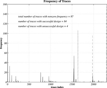
Figure 6 shows how many projects (out of the total 960 projects) followed each specific trace. The promising result is that the distribution of the traces is quite scattered; that is, many projects followed similar traces. Please remember that a specific trace index shows a unique combination of design approaches taken by the set of designer agents. Therefore, the total number of possible traces is the product of the number of design approaches of all the designer agents. For the experiments shown in this paper the total number of possible traces is calculated by multiplying the number of design approaches for four kinematics designers, five structural designers, and one control systems designer. For example, the first kinematics designer has six different design approaches, the second kinematics designer has three approaches, the third one has two design approaches, etc. Therefore, the total number of possible traces is 6 × 3 × 2 × 1 × 4 × 2 × 4 × 2 × 1 × 1 = 2304.

The frequency of traces.
When the system reaches a successful design (i.e., a design that satisfies all the constraints), it records the corresponding trace. No intermediate trace is recorded by the system. Then the system continues with the next design problem. We refer to the set of traces that produced successful designs as “traces with successful design,” or successful traces for short. All the successful traces are used in constructing a set of design methodologies. Among all 2304 possible traces for the experiments reported in this paper, 84 were successful traces (i.e., <4%).
If the system is not able to find a successful design for a specific design problem, it records the trace of its last attempt. We call these traces “traces with unsuccessful design,” or unsuccessful traces for short. Unsuccessful traces are not used in constructing the methodologies.
The total number of successful and unsuccessful traces recorded by the system was 87. Three of these traces never led to a successful design for any of the design problems. Eighty-three of the traces were always successful for at least one design problem. The last trace was a successful trace for a set of design problems but an unsuccessful trace for some other set of design problems. That is, there is one trace that is common between both successful and unsuccessful traces depending on the design problem. As a result, the total number of successful traces in Figure 6 is 84 and the total number of unsuccessful traces is 4.
The low percentage of successful traces indicates that for each group of projects that followed a particular trace there is a unique combination of approaches leading to successful designs, hence, there is a high chance that if similar projects follow the same trace they will succeed in generating a successful design. As a result, the path followed by those projects can lead us to formulating a design methodology for the projects that followed that trace as well as for projects that are similar to those projects.
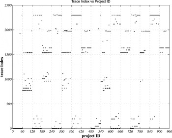
Figure 7 shows how the traces are distributed relative to the projects. It clearly shows that there are some patterns in projects that are taking one particular trace. One of the dominant patterns that is repeated every 60 projects can be visually detected in Figure 7. This pattern matches the change of requirements for the type of the workspace that the robot covers. The grid size of the diagram in Figure 7 is set to 60 projects to help highlighting this pattern.

Traces versus projects.
Observing these patterns provides another promising sign of being able to formulate design methodologies based on the traces of the system. These patterns show that the projects that followed the same traces have common features, for example, they have the same requirements on workspace. This suggests generalizing the set of projects that followed the same trace based on their common features: another step toward formulating methodologies.
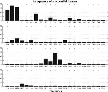
Figure 8 shows the frequency of all 84 successful traces. It is evident from this figure that a small number of traces have very high frequencies (i.e., higher than 20). This is even more good news for being able to find design methodologies. A small number of traces with relatively high frequency shows that even without clustering traces together, we might be able to find methodologies that are based on those traces and still cover a large number of different situations (e.g., 70 different projects).

The frequency of successful traces.
Moreover, existence of a small number of traces with high frequencies helps in clustering traces together. The high-frequency traces can act as seeds for clustering, that is, to absorb the traces with lower frequencies and form generalized traces with even more frequencies.
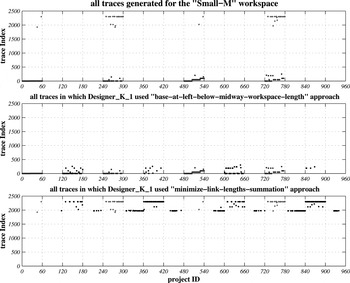
Figure 9 demonstrates that the traces that were followed by projects with common features have common features also. That is, there is a correlation between clusters of projects and clusters of traces. For instance, all the projects that required one specific type of workspace have followed traces that either put the base of the robot below or to the left of the workspace boundary or put the base at a location that minimizes the sum of link lengths.

The correlation between requirement space and trace space.
4. RESULTS
The following summarizes the observations that we have made based on the traces generated by the system (Shakeri, 1998).
- The ratio of the traces taken by the system that led to a successful design compared to all possible traces is quite small: 84/2304 = 0.0365 (3.7%). Hence, we have been able to successfully identify the small percentage of paths that lead to good designs.
- The similarity of traces that produced successful designs for some set of projects clearly shows some patterns. This is a good indicator for being able to cluster groups of traces together.
- There is a correlation between the patterns in groups of traces and groups of problems (i.e., requirements and constraints). This is a promising sign of being able to map clusters of problems to clusters of traces, a major step toward being able to index methodologies.
- The frequency of the traces is not evenly distributed; thus, the coverage of traces are different. This might lead to a way to evaluate the quality of different traces. Similarly, methodologies that are built using different traces might have different quality.
- Due to the preferential order of the use of design approaches within agents, traces are different with regard to the desirability of their approaches. This might lead to another measure for the goodness of a methodology.
4.1. Dependency graph
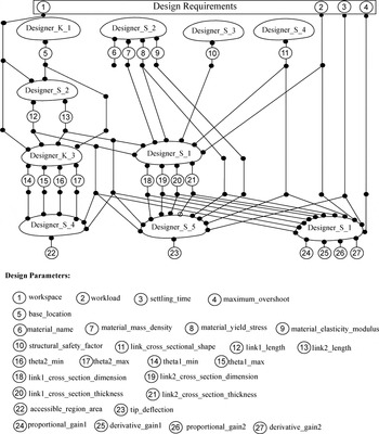
Discovering the dependency between designers is the first set of results that we extract from the traces of the system. Some designers need inputs that are generated by other designers; therefore, they have to wait until the designers that supply input to them finish. Having small designers combined with an opportunistic strategy provides a way to discover dependencies among design parameters automatically. Additionally, the possible concurrency between designers in each design cycle can also be discovered by the system. The dependency graph resulting from the experiments is shown in Figure 10.

A dependency graph for the design of a 2-DOF robot.
The dependency graph shown in Figure 10 is automatically discovered on the fly to be used in the directed backtracking by the agents. When a constraint is violated, the design parameters and the designers affecting the constraint are identified. Based on which designers are responsible for generating those design parameters, a backtracking agenda is prepared and executed. Dependency-directed backtracking is more efficient in recovering from constraint violations.
The dependency graph of Figure 10 also shows that the following objectives for the design process have been achieved:
- Integration. Integration of disciplines has been achieved by agents from different disciplines interacting with one another.
- Information sharing. The links in the dependency graph show the information exchange between different disciplines and designers.
- Collaboration. A mix of designers from different disciplines collaborate with each other at each stage of the process to generate a design that satisfies all the constraints. Collaboration also happens during backtracking when, based on the dependency data, some of the designers may have to change their most desirable decisions for another designer be able to recover from a constraint violation.
- Concurrency. The possible concurrency between different designers has been discovered.
- Bottlenecks. The figure also shows that in the second row only Designer_K_2 can design. As a result, the design process at this row is not as efficient as the other stages. Therefore, this is a bottleneck.
4.2. Clustering the traces
To be able to extract design methodologies based on the traces generated by the system we need to cluster similar traces together. The similarity of two traces can be measured based on how their ingredient design approaches differ from each other. The similarity (i.e., distance) between two traces is calculated by adding together a set of “0s” and “1s.” A “0” is added to the distance when the design approaches of the same designer in both traces are the same. A “1” is added when a particular designer has used two different approaches for the two traces being compared (Shakeri, 1998).
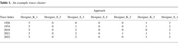
A generalized trace will replace each cluster of similar traces. Later we will find a correlation between each generalized trace and subsets of requirements and constraints. Suppose that the five traces shown in Table 1 are clustered together.
For an explanation of the columns of Table 1 please see Section 3.2. A candidate generalized trace for the cluster of Table 1 is shown in Table 2.
An example trace cluster

Generalized trace for trace cluster of Table 1

4.2.1. Goodness of a cluster of traces
The goodness of a cluster of traces can be measured based on two factors:
1. The number of projects that followed the traces clustered: coverage. Coverage is a measure of how many different design situations (i.e., projects) are covered by the traces clustered. We calculate the coverage of a cluster by adding the frequencies of the traces clustered. Methodologies that are generated from clusters with higher coverage are applicable to a wider range of design problems that have more variations in their requirements. We calculate the coverage of a cluster by adding the coverage of traces it contains using Eq. (1).

where pi is the number of projects covered by trace i and traces is the number of traces in the cluster.
2. The number of variations of design approaches in the cluster: uniformity. Traces differ from each other because of the difference in the design approaches that designer agents have used. Clustering accumulates these different approaches in one place causing some loss of information. That is, instead of being specific about what approach should be used for the situations covered (i.e., projects covered), the cluster suggests a collection of the possible approaches. We refer to this measure as the uniformity of the cluster. The most uniform cluster is the one that does not have any variation in its approaches. Two factors affect the uniformity of a cluster:
a. the number of designers that vary their approach in the cluster and
b. the amount of variation for each designer that varies its approach.
We give more credit to those clusters with fewer designers that vary their approach.
Based on the above factors we assign a number to the uniformity of a cluster using Eq. (2).

where aj is the number of approaches accumulated for designer j in the cluster and designers is the number of designers in the generalized trace.
The goodness of a cluster of traces (GC) is defined as the product of its coverage and its uniformity, as shown in Eq. (3).

To be applicable to general situations the coverage and the uniformity of the cluster should be normalized. In general situations the number of designers may vary from problem to problem. Normalization is needed also when we want to compare the goodness of clusters from different sets of experiments and across different domains. The coverage can be normalized by dividing the resulting number by the total number of projects in the experiment (Tp). The uniformity can be normalized by dividing it by the maximum score for the uniformity of the cluster (equal to the total number of participant designers, Td).
Normalizing the goodness generates very small numbers that are hard to compare to each other. To increase the resolution we multiply the result by 1000. The general equation for calculating the normalized goodness of a cluster (GCN) is shown in Eq. (4).

4.3. Formulating methodologies
To be able to formulate methodologies we need to find correlations between subsets of projects and clusters of traces. A correlation exists between a subset of projects and a specific trace or cluster of similar traces, if the projects have followed that trace or cluster of traces.
Selection of the final methodologies from the set of candidate methodologies is a trade-off process. At one end there are methodologies that are very detailed but are not applicable to many projects. On the other end there are methodologies with few details, but which are applicable to a large number of projects.
The generality of the methodologies generated based on clusters of traces increases as the height of the cluster in the cluster tree increases (i.e., as additional similar clusters are combined into new clusters). On the other hand, as more clusters get grouped together the number of projects included grows and, as a result, increases the applicability of the cluster. However, to compare methodologies that are derived from clusters with the same height in the cluster tree we can use the goodness of the clusters.
4.4. First set of clusters
To demonstrate the approach of extracting methodologies, in this section we use clusters at height 1 in the cluster tree. These clusters generate the most detailed methodologies (except for methodologies based on traces themselves). The process of extracting the methodologies can be automated based on the approach proposed by Reich and Fenves (1991). The idea is instead of clustering the traces and then clustering the problems that have followed each cluster, merge the traces and problems, and cluster the resulted combined trace. In this work we constructed the candidate methodologies manually to gain better insight into the behavior of the system.
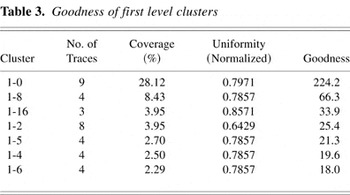
The first round of clustering traces has led to 34 clusters. The most populated clusters along with their goodness number based on Eq. (3) are shown in Table 3.
Goodness of first level clusters

In Table 3 the name of a cluster is composed of two numbers separated by a dash. The first number is the height of the cluster in the tree. The second is the index of the cluster at the specific height.
4.4.1. Cluster 1-0
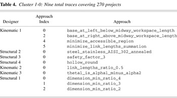
The first cluster, Cluster 1-0, covers 270 projects and includes nine traces (see Table 4). Roughly speaking, Cluster 1-0 is the collection of projects with mostly loose constraints and requirements. Projects that have tighter requirements and constraints have used approaches 4 and 5 of the Designer_K_1 to reduce the length of the robot's links.
Cluster 1-0: Nine total traces covering 270 projects

For example, the first project that has taken a different path than of the Cluster 1-0 is project 45 in which Designer_K_3 has chosen a right-hand configuration for the robot arm as opposed to a left-hand configuration. Both projects in the neighborhood of project 45 followed the path shown in Cluster 1-0.
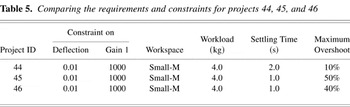
Let us look at the requirements and constraints for these three projects to see what has caused for project 45 to take a different route (see Table 5).
Comparing the requirements and constraints for projects 44, 45, and 46

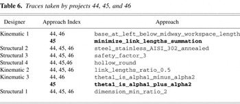
Project 45 has taken the trace 1926, while projects 44 and 46 have both followed the route of trace 2 (see Table 6).
Traces taken by projects 44, 45, and 46

Trace 1926, which is followed by Project 45, is clustered with eight other traces into Cluster 1-0, which due to its small population of projects, and traces will be dropped from consideration for generating methodologies at this level.
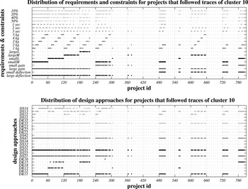
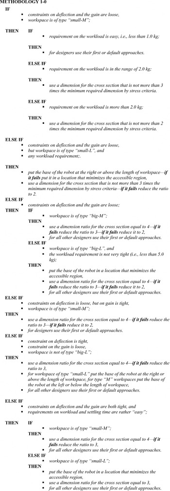
Based on the correlation between the change of requirements and constraints with the change of design approaches in Figure 11, the candidate methodology in Figure 12 is extracted.

Comparing the trace of constraints and requirements with the trace of design approaches for projects that followed cluster 1-0.

Methodology 1-0.
5. EVALUATION OF THE RESULTS
Our approach has been designed and implemented to produce good design methodologies. The following is the list of the features that better design methodologies should have, and how our approach produces them:
- Take less time. The methodologies generated are based on successful traces. Therefore, there is a high chance that following those methodologies takes us directly to a solution that satisfies all the constraints along the way. That is, less iteration is needed, and thus time is saved. The system first follows the traces that have higher priority design approaches. Giving more priority to design approaches that takes less time makes the methodologies even more time effective.
- Cause fewer design process failures. The methodologies generated are based on traces of the system that have succeeded in producing a successful design and thus have less chance of encountering constraint violations.
- Produce better designs. Better designs are those with better quality or those that are simpler. We did not consider the quality of the product in producing traces. The reason is that this is an area of research that has been investigated thoroughly, and many good approaches have been developed for optimizing design products, for example, the methods from multidisciplinary design optimization. One can incorporate product quality into the traces generated by introducing global constraints that define the boundaries of near-optimal designs.
- Work for a wide range of design requirements. In producing methodologies we pick the cluster of traces whose coverage combined with their uniformity is higher than others. This leads to methodologies that are applicable to a wide range of different situations.
- Integrate different disciplines. The dependency graph generated clearly shows that different disciplines are integrated in the design process. For example, in the last round, designers from all three disciplines participated in the process of design. Integration of the disciplines is evident also from the methodologies generated.
- Conduct design concurrently. The dependency graph shows how multiple designers can design simultaneously. Implementation of the “concurrency strategy” plus the “opportunistic strategy” conducts the design process among different designers concurrently.
- Consume less resources. Less resources (e.g., time and money) are spent in the design process due to features that are incorporated into the design methodologies (e.g., integration, concurrency, less failure, etc.).
- Reduce load on designers. Having access to design methodologies that are built systematically based on the latest available technology reduces the load on designers, especially the generalists that can now spend more time on more creative parts of the design process.
5.1. Contributions
Investigating and developing computational and knowledge-based models for the design process has provided us with better insight into how a real design process might be conducted more efficiently.
Examples include how the design tasks should be delegated to the members of a design team so that little overlap happens in carrying out the tasks; to reduce the number of conflicts; reorganize the teams so that all decisions about one design parameter are taken in one place, that is, no two different designer decide about the same parameter; by discovering the dependencies between designers, dependency-directed backtracking prevents the designers that will not have any effect on violated constraints from having to redo their work.
A summary of the other theoretical contributions follows:
- Extending the technique of analysis by simulation to the area of analyzing design methodologies and, in general, to synthesizing the emergent behavior of complex systems.
- Decomposing the design process into small designers, coordinators, databases, and other utility agents, as is done for RD, can be used in real design processes.
- Approximating the continuous design process with a discrete process comprising of cycles of run–analysis–update.
- Resolving conflicts between different participants in design can be aided by breaking the design knowledge into small pieces at the decision points (i.e., a decision about assigning values to design parameters). In these situations we will have a set of (atomic) design methods where some of them decide about the same parameter. Collect and bundle the design methods that are about the same design parameters into one design agent. In each agent, order and prioritize each method and let the agent decide what method it should use for assigning a value to the associated parameter. In this situation there is no conflict between designer agents in assigning values to design parameters. The same approach can be used for the control knowledge in which designer agents might not agree on what the order of the design tasks should be.
- Providing an approach for analyzing current methodologies for flaws and bottlenecks, and suggesting necessary refinements. New methodologies can be customized so that they are biased toward specific objectives such as manufacturability. By applying this approach the response time for the incorporation of new technologies or new design methods into design processes will be reduced. Methodologies can be refined as soon as a change occurs in the market or in the organization of the company.
- Developing algorithms for backtracking led us to an approach for how to break the design knowledge into pieces: break the design knowledge in a way that the most expensive methods are located in the shallower depths of the dependency graph.
The experiments conducted in this research revealed some interesting results. In summary, an approach for discovering the dependency relations between design parameters is to use a multiagent design system. In addition, the experimental studies reveal some valuable information regarding the sensitivity of the design to the design approaches as well as to various subsets of design parameters. The design process simulation approach can be used as an analysis tool, and for sensitivity studies in which quantitative and qualitative measurements are formed to show the effect of inputs (requirements/constraints) on outputs (the product attributes).
5.2. Future work
This research could be extended in a variety of directions to increase its scope and to improve the chances for success in real design practices.
- Applying the approach to other types of design problems other than nonroutine parametric design, such as configuration design. This is a direction that increases the scope of the proposed approach. Obviously, one important feature that should exist for these new types of design problems is that they should be able to be automated via an MAS, even if it is only in a simplified version.
- Applying the approach to other multidisciplinary domains such as automotive design, electronics packaging design, or building design. This would help to gain better insight into the problem and enhance the generality of the approach.
- Discovering the rules for simplifying the process. To be able to discover design methodologies based on simulation of the design process it is not necessary to model the design process in full detail. Similar to the simulation of physical phenomenon in engineering analysis, we can simulate a simplified version of the design process and still get the design methodologies that are helpful for the real situations. The rules for these simplifications and approaches and tools should be developed for this purpose.
- Evaluation of the methodologies in real situations. The design methodologies developed by the approach proposed should be evaluated in those real design situations in which human designers use such methodologies, and any enhancement in the design process should be noted. Also, the lesson we have learned with respect to the organizational side of the design process can be tested in design processes using human designers to see whether any improvements happen.
- The effect of scaling up the approach should be investigated. Larger design processes with more disciplines and design parameters must be investigated.
- Enrich the design methodologies. Design methodologies can contain more knowledge about not only the design approaches but also about control aspects.
- Biased methodologies could be generated using this approach. Design methodologies that are biased toward manufacturability, for example, can be another area of further research.
- Change the order of approaches. It would be useful to investigate the effect of the order of selection of the design approaches on the traces produced.
- Convert the tool to a sensitivity analysis tool or even an optimization tool. As we used the multiagent design system to discover sensitive parameters as well as their boundaries, more research can be done to convert the system to an optimization tool. Such an approach to optimization is especially attractive for domains that do not conform to a completely mathematical form allowing classical optimization tools to be used.
- Introduce new types of design approaches into the design process. Heuristic, statistical, and probabilistic approaches could be tried.
- Close the feedback loop around the system in which the methodologies generated by the system are fed back into it to further refine the methodology, that is, to force the system to use the methodologies generated for similar problems and measure the improvement.
- Investigate the effect of changing the resolution of the set of constraints and requirements. Use a concept similar to adaptive mesh generation in the finite element method to find the best grid and/or find the areas of high gradient. Enhance the resolution of the constraint-requirement grid so that the system covers more design problems.
- Investigate the effect of the design knowledge used to produce correct designs on generating the right methodologies. That is, find the answer to the following questions: what is the trade-off between the design quality and correct traces (and, hence, correct methodologies)? Can we remove some of the design knowledge from the system (knowing that it will produce inferior designs) but still obtain correct design methodologies? That is, can the knowledge engineering, and implementation stages be substantially simplified?
Simulation of complex systems using agents can be a powerful tool in analyzing why those systems behave in a certain way. Using our approach complex systems can be designed to have some desired emergent behavior. Multidisciplinary design processes are one example of complex systems whose emergent behavior is hard to anticipate. Other areas that are similar to the multidisciplinary design process in having an emergent behavior are “supply chains in manufacturing enterprises” and “shop floor job scheduling.”
6. CONCLUSIONS
In this paper we have shown that computers can provide us with better ways of doing design by discovering superior design methodologies that integrate different points of view of multiple disciplines in the design process. Analyzing the behavior of physical systems in engineering applications by computer simulation using mathematical models has been a powerful tool in engineering, reducing costs and time in comparison to physical prototyping and experimentation. We showed that it is possible to use computers to simulate the design process. We can analyze the results of the simulation to synthesize design methodologies that have superior features. The approach that we have proposed has been developed based on a knowledge-based model of the design process for parametric design problems. We feel that this novel approach, while requiring more investigation, shows considerable promise.
References
REFERENCES
Badhrinath, K. &
Jagannatha Rao, J.R.
(1996).
Modeling for concurrent design using game theory
formulations.
Concurrent Engineering: Research and Applications
4(4),
389–399.CrossRefGoogle Scholar
Brown, D.C. &
Douglas, R.
(1993).
Concurrent accumulation of knowledge: A view of CE. In
The Handbook of Concurrent Design and Manufacturing
(Parsaei, H.R. &
Sullivan, W.G., Eds.), pp.
402–412.
London:
Chapman & Hall.
Dasgupta, S.
(1989).
The structure of design processes. In
Advances in Computers
(Yovits, M.D., Ed.),
Vol. 28, pp.
1–67.
New York:
Academic.CrossRef
Huang, G.Q. &
Brandon, J.A.
(1993).
Cooperating Expert Systems in Mechanical Systems.
New York:
Wiley.
Jackson, P.
(1990).
Introduction to Expert Systems.
Reading, MA:
Addison–Wesley.
Kannapan, S.M. &
Marshek, K.M.
(1992).
Engineering design methodologies: A new perspective. In
Intelligent Design and Manufacturing
(Kusiak, A., Ed.), pp.
3–38.
New York:
Wiley.
Klein, M.
(1991).
Supporting conflict resolution in cooperative design systems.
IEEE Transactions on Systems, Man, and Cybernetics
21(6),
1379–1389.CrossRefGoogle Scholar
Lander, S.E.
(1997).
Issues in multi-agent design systems.
IEEE Expert: Intelligent Systems and their Applications
12(2),
18–26.CrossRefGoogle Scholar
Langley, P.
(1996).
Elements of Machine Learning.
San Francisco, CA:
Morgan Kaufmann.
NSF.
(1996).
Research Opportunities in Engineering Design
(Shah, J., Ed.).
NSF Strategic Planning Workshop Final Report.
Reich, Y. &
Fenves, S.J.
(1991).
The formation and use of abstract concepts in design. In
Concept Formation: Knowledge and Experience in Unsupervised
Learning
(Fisher, D.H.,
Pazzani, M.J. &
Langley, P., Eds.), pp.
323–353.
San Francisco, CA:
Morgan Kaufmann.CrossRef
Shakeri, C.
(1998).
Discovery of design methodologies for the integration of
multi-disciplinary design problems.
PhD Thesis.
Worcester Polytechnic Institute.
Sobolewski, M.
(1996).
Multiagent knowledge-based environment for concurrent engineering
applications.
Concurrent Engineering: Research and Applications
4(1),
89–97.CrossRefGoogle Scholar
Wooldridge, M.
(1997).
Agent-based software engineering.
IEEE Transactions on Software Engineering
144(1),
26–37.CrossRefGoogle Scholar
The design parameters of a 2-DOF planar robot.
The knowledge-based approach to generating design methodologies.
Integration by breaking up the knowledge into smaller segments.
The opportunistic strategy in activating design methods.
The architecture of the multiagent design system.
The frequency of traces.
Traces versus projects.
The frequency of successful traces.
The correlation between requirement space and trace space.
A dependency graph for the design of a 2-DOF robot.
An example trace cluster

Generalized trace for trace cluster of Table 1
Goodness of first level clusters
Cluster 1-0: Nine total traces covering 270 projects
Comparing the requirements and constraints for projects 44, 45, and 46
Traces taken by projects 44, 45, and 46
Comparing the trace of constraints and requirements with the trace of design approaches for projects that followed cluster 1-0.
Methodology 1-0.
 You have
Access
- 4
- Cited by