





Impact statement
This research advances bio-digital design by establishing a preliminary, replicable framework for bio-receptive architectural surfaces, validated through the SPIKA installation at the Milan Triennale. It delivers a process-oriented comparison of three fabrication paradigms – subtractive (CNC-milled wood), formative (mould-cast concrete) and additive (3D-printed clay) – documenting parametric workflows and material-specific parameters that link manufacturing processes to potential ecological performance. By demonstrating promising initial biological colonization across all substrate types within 75 days of on-site inoculation, the project validates the feasibility of moving bio-receptive design from laboratory settings to real-world architectural applications as an exploratory prototype. SPIKA reconceptualizes the architectural façade as a dynamic ecological interface, offering a transferable model for regenerative practices that integrate computation, material science and microbiology. This work provides designers with practical strategies for enhancing urban biodiversity and supporting ecological succession, while acknowledging the need for future quantitative validation.
Introduction
Contemporary urban environments increasingly recognize the need to integrate ecological performance within architectural design. However, practical methodologies for developing building surfaces that actively support biological life remain underexplored. This paper addresses this gap by asking: How can subtractive, formative and additive fabrication paradigms be systematically compared in the production of bio-receptive architectural surfaces, and what are the limits of such a comparison in the absence of quantitative biological monitoring?
It presents SPIKA, a bio-digital design project that develops and explores strategies for bio-receptive architectural surfaces. Drawing inspiration from defensive natural morphologies and self-organized biological patterns such as reaction-diffusion, the research translates these principles into performative surface geometries. Importantly, existing literature has established that morphological parameters such as porosity, rugosity, pH and surface texture significantly influence bioreceptivity (Abdallah and Estévez, Reference Abdallah and Estévez2023; Guillitte, Reference Guillitte1995; Pollini et al. Reference Pollini, Contardo, Paciotti, Rognoli, Vaes and Verlinden2023). However, the specific relationship between digitally fabricated spike geometries and colonization dynamics remains underexamined. This study does not isolate morphology as an independent variable but instead examines how fabrication constraints shape achievable morphologies and their initial ecological responses. It is limited to indoor conditions and does not address long-term ecological succession or outdoor environmental variability. Accordingly, the focus remains on early-stage growth behaviour and material–geometry interactions rather than full lifecycle ecological outcomes.
Through a systematic design-to-fabrication workflow, sixty-eight panels were produced using three distinct manufacturing methods with three corresponding materials – CNC-milled wood, mould-cast concrete and 3D-printed clay. Following fabrication, all substrates were inoculated with a cryptogamic-microbial culture collected from Parco Sempione, Milan. Validated through public exhibition at the Milan Triennale, SPIKA establishes an exploratory framework for reconceptualizing architectural façades as dynamic ecological interfaces that can support urban biodiversity and regenerative design practices. The primary contribution of this pictorial is the detailed documentation of fabrication parameters and workflows. The biological observations are presented as preliminary and qualitative rather than as a controlled comparative experiment.
Digital 3D modelling
A tessellated assembly of sixty-eight panels was digitally modelled using Rhinoceros 3D software in combination with the Grasshopper parametric modelling extension and AutoCAD software.
Spiky surface pattern
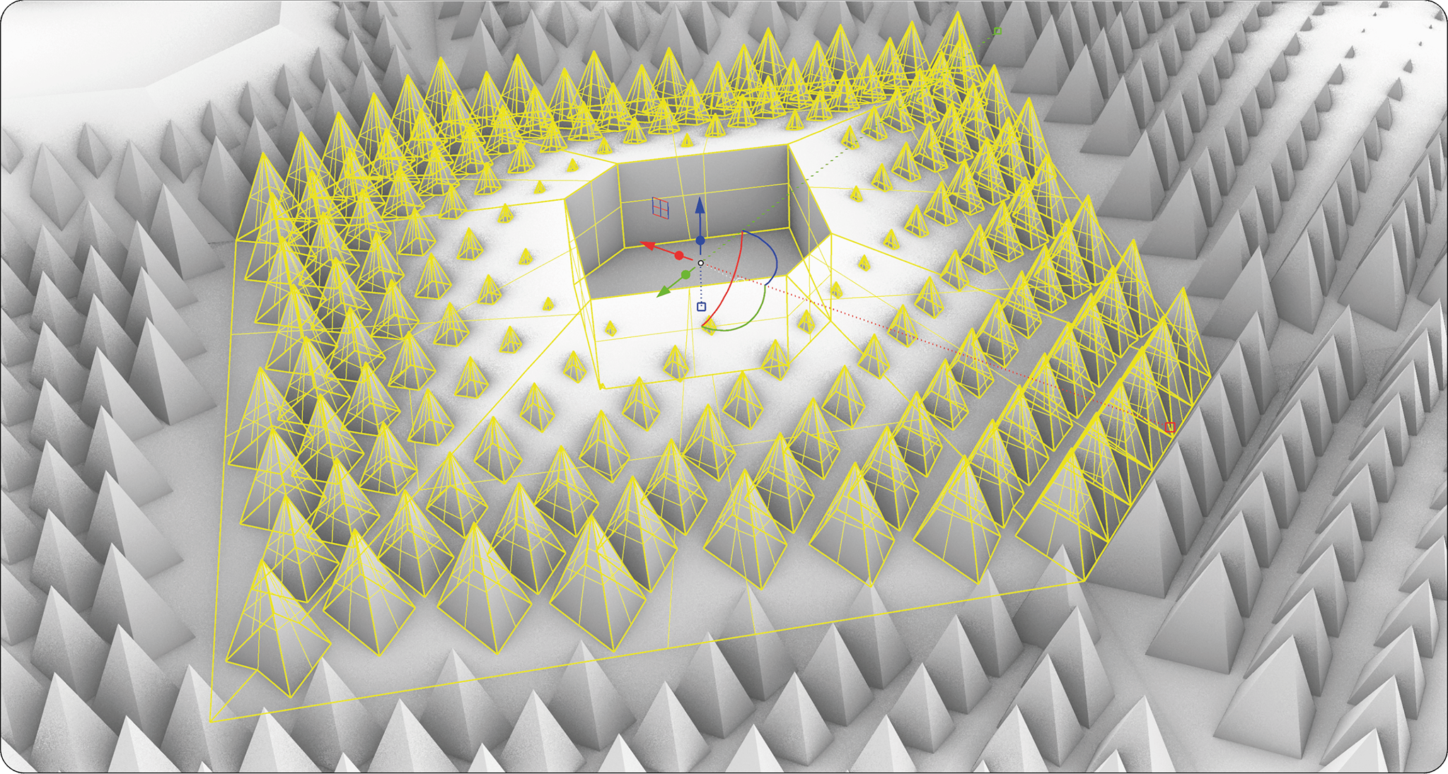
The computational workflow allowed precise control over panel geometry, subdivision and surface articulation. The resulting surface pattern draws inspiration from the defensive mechanisms found in natural systems, translating adaptive, survival-driven morphologies into performative bio-receptive surfaces (Figure 1).
3D modelling of the spiky surface pattern (Rhinoceros3D and Grasshopper).

Figure 1. Long description
A perspective rendering of a 3D digital model of tessellated hexagonal panels designed with distributed pyramidal spikes for bioreceptive performanc. A central panel highlighted in yellow is shown, illustrating the parametric generation and bio-inspired spiky surface pattern developed using Rhinoceros3D and Grasshopper.
Reaction-diffusion surface pattern
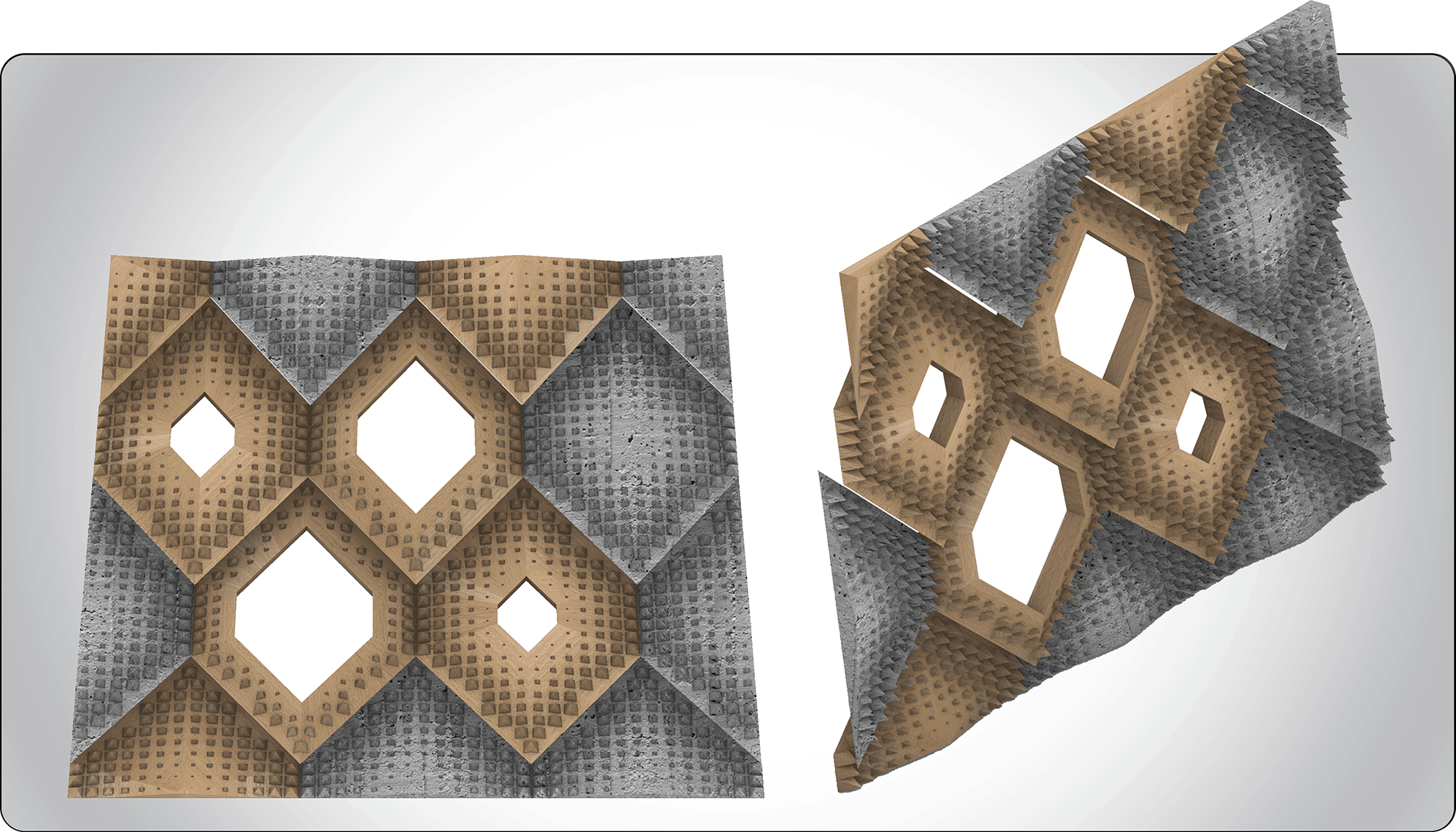
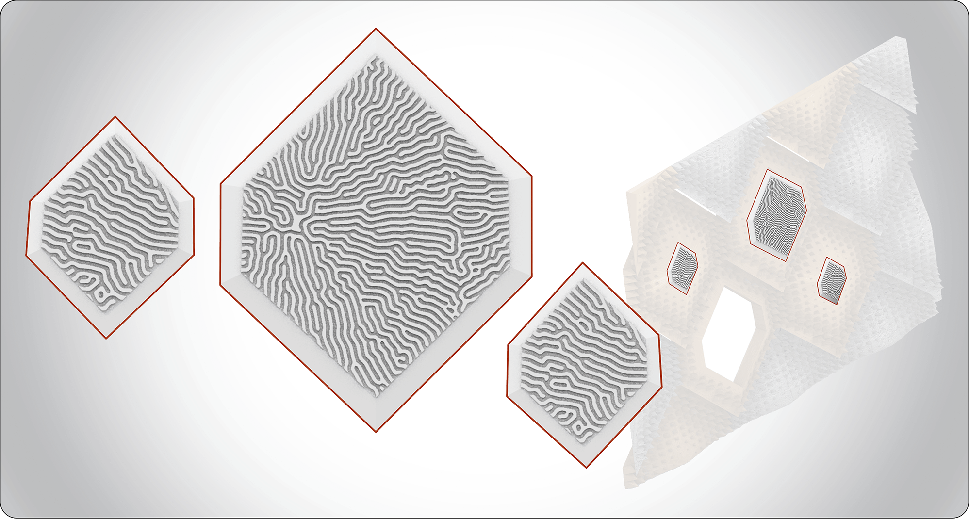
Figures 1–3 outline the computational development and digital simulation of bio-receptive surface geometries generated through Rhinoceros3D, Grasshopper and AutoCAD workflows. Figure 1 presents the parametric modelling process used to create the spiky surface pattern for the wood and concrete panels, characterized by pointed protrusions distributed across a tessellated geometry to increase surface complexity. Figure 2 demonstrates the resulting digital simulation of the façade system integrating both wood and concrete panels. Figure 3 further complements this topological investigation through the incorporation of softer geometries combined with reaction–diffusion patterns for the clay panels.
Digital simulation of the spiky surface pattern (Rhinoceros3D).

Figure 2. Long description
A rendering showing front and perspective views of a tessellated assembly composed of wood and concrete panels. The design integrates a spiky surface pattern and illustrates panel articulation within the modular structure. The visualization highlights the overall spatial composition, and the interaction between panel types.
Digital drawing of the reaction-diffusion surface pattern (AutoCad and Rhinoceros3D).

Figure 3. Long description
A 3D rendering focusing on the design of clay panels with reaction–diffusion surface patterns for bioreceptive performance. The visualization shows modular panel geometries and illustrates the integration of clay panels within the overall tessellation.
Unlike the spiky surface pattern, the clay tiles adopt softer geometries inspired by beetle carvings on wooden surfaces. These macro-geometries are analogous to reaction-diffusion patterns, where local interactions produce self-organized surface formations, reflecting principles of biomimicry and parasitic ecological interactions (Figure 3).
Parametric fabrication methods
Panels were fabricated from three different materials – wood, concrete and clay – to qualitatively explore the biological growth supported by each under similar indoor environmental conditions. Subtractive, formative and additive manufacturing methods were employed. Each material is characterized by a distinct surface geometry directly informed by its respective fabrication method, thereby establishing a relationship between manufacturing process and material expression.
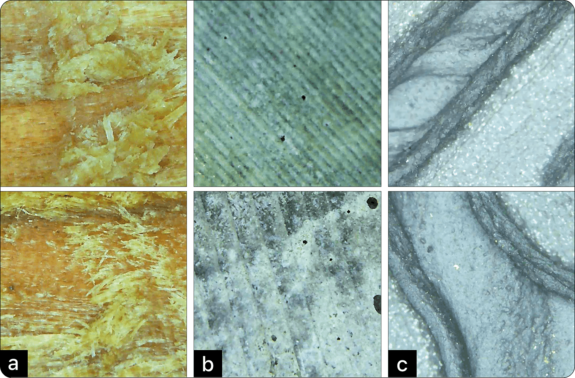
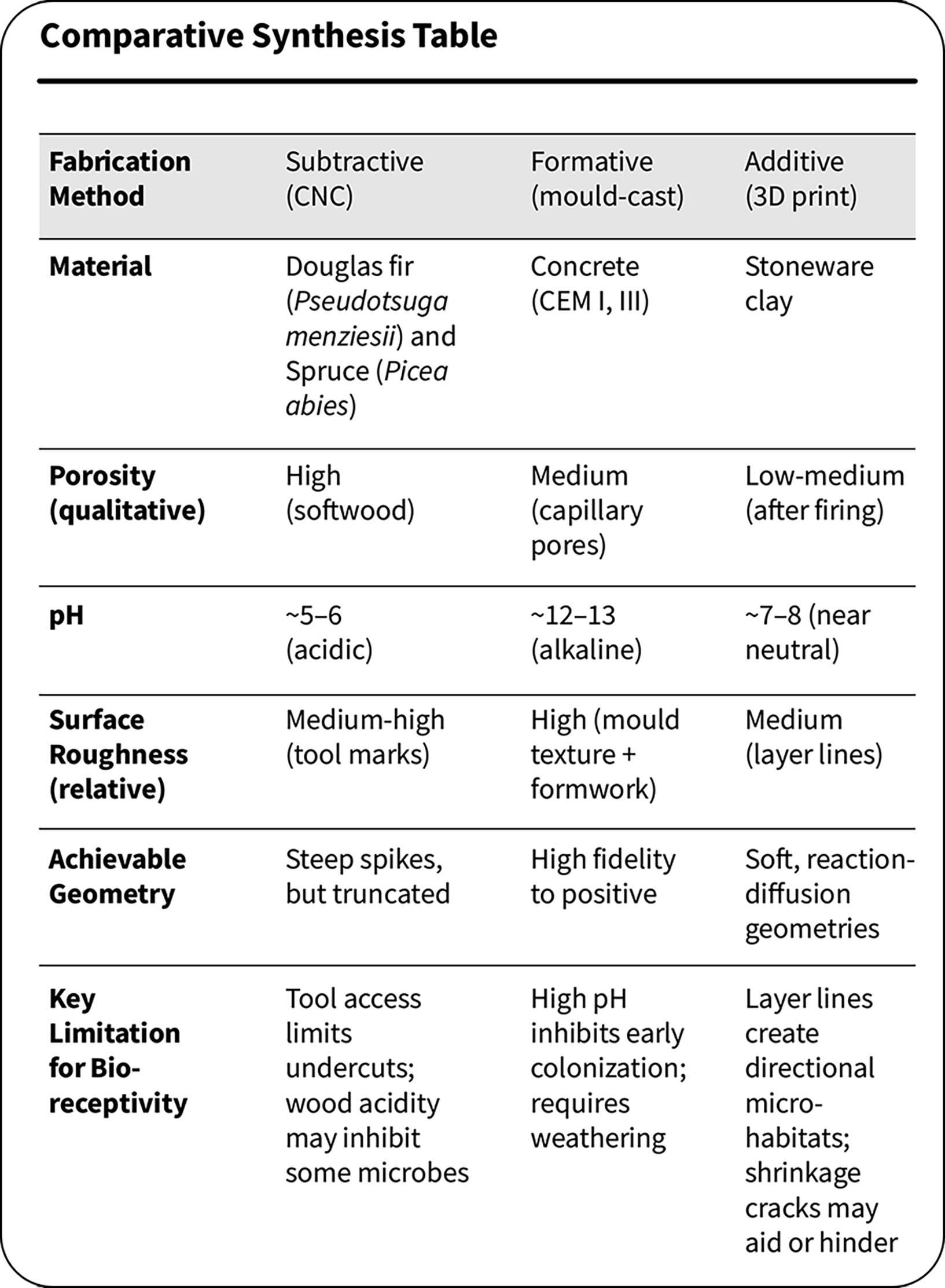
Figure 4 provides a side-by-side visual comparison of the resulting surface textures at 20× magnification. Figure 12 (see page 6) summarizes the key fabrication parameters, material properties relevant to bioreceptivity (porosity, pH, surface roughness), and the specific geometric outcomes achievable per method.
Surface textures of (a) CNC-milled wood, (b) mould-cast concrete and (c) 3D-printed clay substrates. 20× magnification.

Figure 4. Long description
A side-by-side comparison of surface textures from three fabrication methods, including CNC–milled wood, mould-cast concrete, and 3D–printed clay substrates. All samples are shown at 20× magnification to highlight differences in surface roughness and micro-scale texture formation resulting from each manufacturing process. The comparison emphasizes how fabrication technique influences the resulting surface morphology and material expression.
Subtractive manufacturing: CNC milling
Two softwood species were selected for this study: Douglas fir (Pseudotsuga menziesii) and spruce (Picea abies), both in their chemically untreated construction-grade form. These species were chosen because, as softwoods, they exhibit higher porosity and lower density than hardwoods – properties that are known to enhance bio-receptive potential. Their selection was also motivated by their widespread availability in Europe, particularly in Belgium, where subsequent experiments are planned. The wood samples were procured in March 2025 from Hanssens Hout, a wood supplier based in Ghent, Belgium.
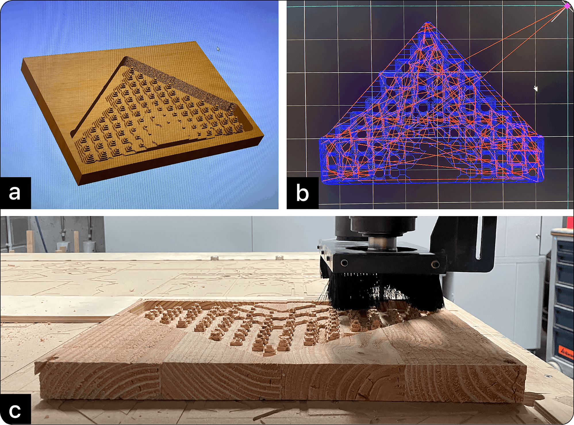
The wood panels were fabricated using a subtractive CNC-milling process. All panels were prepared in the Wood Workshop facilities of the LUCA School of Arts. The wood planks were initially cut using professional woodworking equipment and subsequently glued with Rectavit 210 Classic wood adhesive to produce blocks suitable for CNC milling. The 3-axis CNC milling was performed using a Colinbus machine, manufactured by CNC Studio (Figure 5).
Programming CNC machine: (a) Tool-path simulation in Aspire software, (b) G-code progression on controller screen, (c) CNC milling on wood block.

Figure 5. Long description
A step-by-step visualization of the CNC machining process showing the programming and fabrication workflow. The sequence includes tool–path simulation in Aspire software, real–time G–code progression displayed on the machine controller screen, and the final CNC milling operation performed on a wood block. The figure illustrates the transition from digital model preparation to physical material fabrication, highlighting the relationship between computational design and manufacturing.
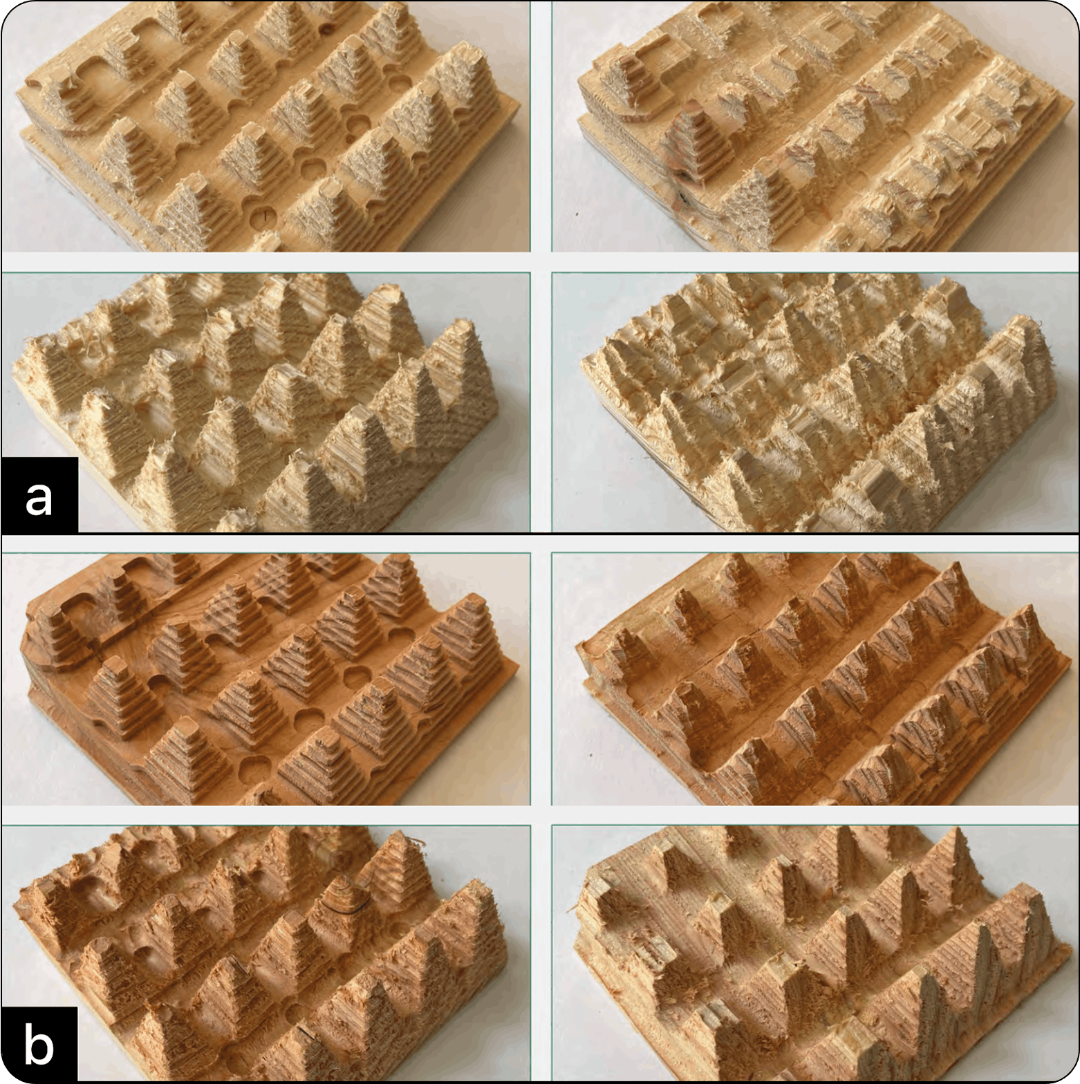
The parameter combination found to be most effective for both Douglas fir and spruce consisted roughing path, a 5.94 mm step-over (99.00%), a 6 mm flat-end drill bit and a spindle speed of 20,000 rpm. These settings provided an optimal balance between detail fidelity, structural integrity and surface quality across both wood types. As a result of these parameters, the initial 3D-modelled spiky geometry was slightly modified across the wood panels (Figure 6).
Evaluation of G-code parameter variations to optimize pattern fidelity and surface roughness on (a) spruce pine and (b) douglas fir woods.

Figure 6. Long description
A comparative imaging of four spruce pine and four Douglas fir wood samples produced using identical CNC milling parameters. The study highlights how different wood species respond to the same machining conditions, revealing variations in surface texture and material behavior. The comparison emphasizes the influence of intrinsic material properties on the resulted surface pattern.
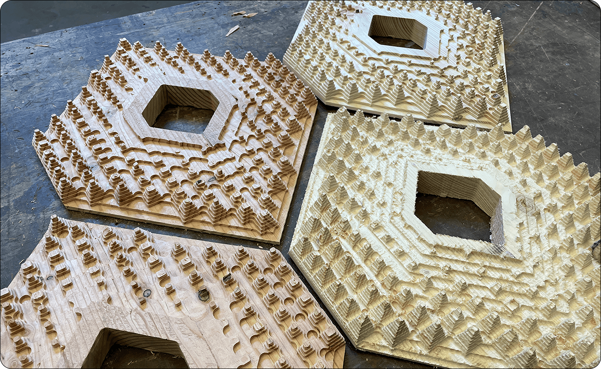
Figures 5–7 present the transition from computational fabrication workflows to the production of tangible bioreceptive prototypes through CNC milling processes. Figure 5 presents the digital preparation and machining sequence, including the tool-path simulation in Aspire software, the visualization of G-code progression on the CNC controller interface and the milling process performed on wood blocks. Figure 6 documents the evaluation of different G-code parameter variations used to optimize pattern fidelity and surface roughness on spruce pine and Douglas fir specimens, assessing the material response to fabrication constraints and textural resolution. Figure 7 provides an overview of the final series of CNC-milled wood panels, comparing the resulting prototypes produced in Douglas fir and spruce pine and demonstrating the translation of computational surface geometries into physical bioreceptive architectural components.
Overview of the final series of CNC-milled wood panels (Douglas fir on the left side and spruce pine on the right side).

Formative manufacturing: mould-casting
Concrete panels were fabricated using a two-stage workflow: (1) silicone mould production from 3D-printed positives and (2) repeated concrete casting in two cement types (CEM I and CEM III) to generate a full set of tiles.
The moulds were made from 3D-printed positive tiles produced at LUCA School of Arts. Positives were printed in PLA on Prusa and Ultimaker printers. Each mould was prepared on a laser-cut MDF base, with temporary cardboard borders constructed around the perimeter to contain the silicone during casting.
Before pouring silicone, the printed positives were coated with a brushed layer of Pattex wood glue diluted with water. This layer was left to dry completely and served as a separating/sealing layer between the PLA and silicone to support clean demoulding.
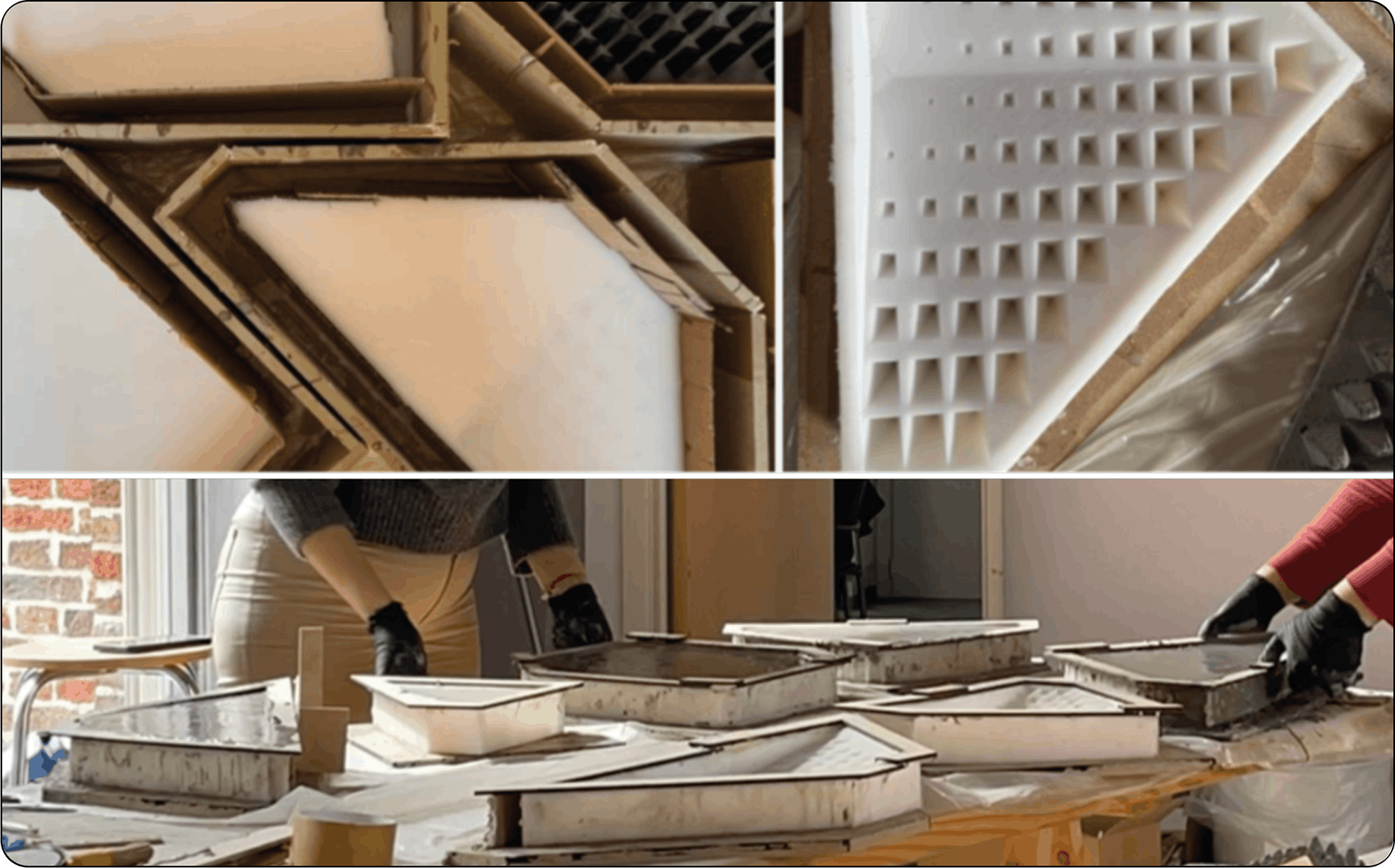
Silicone moulds were then cast using “Siliconen Rubber Shore 25, Mallen gietsiliconen (A+B),” mixed according to 100:30 ratio. An initial plan was to apply the silicone in multiple layers to reduce material use; however, due to the steep spike geometry and time constraints, the process was changed to a full-pour method. Cardboard borders were therefore set to create an approximately 1 cm-thick silicone body around the mould, and the silicone was poured in one complete cast. The moulds were left to cure at room temperature for approximately 2–3 days and then demoulded carefully using hand tools to avoid damaging fine spike features.
Concrete tiles were produced by casting into the silicone moulds. Prior to casting, the silicone surfaces were coated with polyvinyl alcohol (PVA) as a release agent and left to dry.
Concrete was mixed without additives using a simple ratio of 1 part cement (either CEM I or CEM III), 2 parts sand and approximately 0.6 part water (adjusted slightly as needed to reach workable consistency). The sand used was Rivierzand (river sand) with a 0–4 mm grading (25 kg bag, Hubo).
After mixing, concrete was poured into the moulds and compacted using a manual vibration technique: each mould was placed on a dedicated MDF support board, and after pouring the board was repeatedly lifted slightly at one edge and slammed down onto the table to vibrate the mould and help the mix settle into fine details and release entrapped air. This was repeated frequently for approximately 10 minutes per cast (Figure 8).
Silicon mould-making and casting processes of the concrete panels.

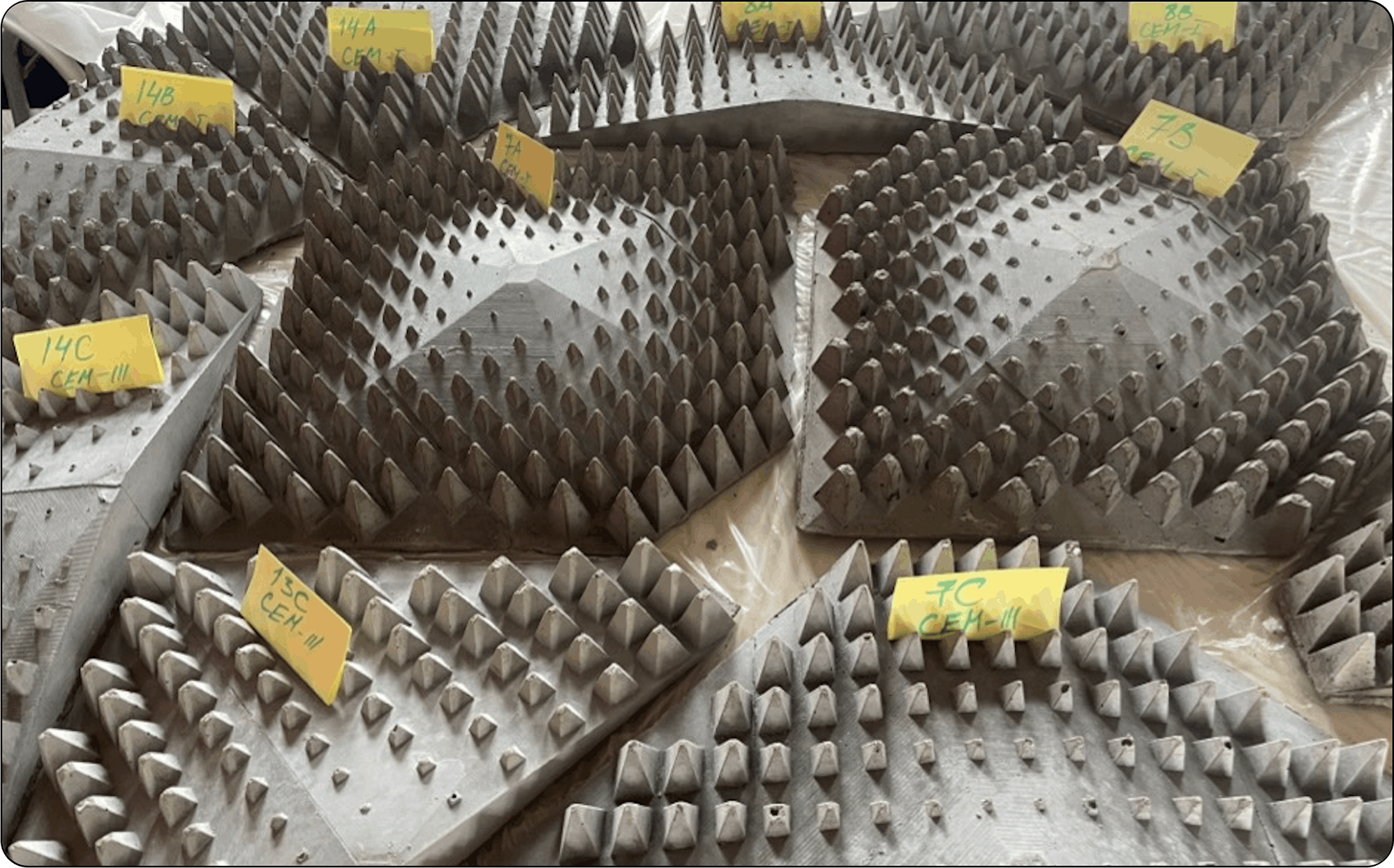
Panels were left to cure at room temperature and demoulded after approximately 2–3 days, followed by continued air curing (Figure 9).
Overview of the final series of casted concrete panels (CEM I or CEM III).

Figures 8 and 9 document the transition from mould fabrication to the production of cast concrete bioreceptive prototypes. Figure 8 presents the silicone mould-making and casting processes developed for the concrete panels, highlighting the translation of digitally generated surface geometries into reproducible casting systems. Figure 9 shows the final series of cast concrete panels produced using CEM I and CEM III cement formulations, enabling a comparative evaluation of their material characteristics, surface resolution and potential bioreceptive performance.
Additive manufacturing: 3D printing
The clay panels were fabricated at the LUCA School of Arts facilities using a LUTUM 5 clay 3D printer supplied by VormVrij Factory. Stoneware clay was chosen for its strength and versatility for outdoor and architectural uses. The clay was purchased from Colpaert, Ghent, and was NIGRA 20/02 chamotte clay (0–0.2 mm grog, 10 kg bags).
To achieve a consistency suitable for syringe loading, the clay paste initially prepared with 15% water content was found to be excessively viscous for clay-based 3D printing. The formulation was therefore adjusted by increasing the total water content to 30% (by weight) relative to the dry clay mass.
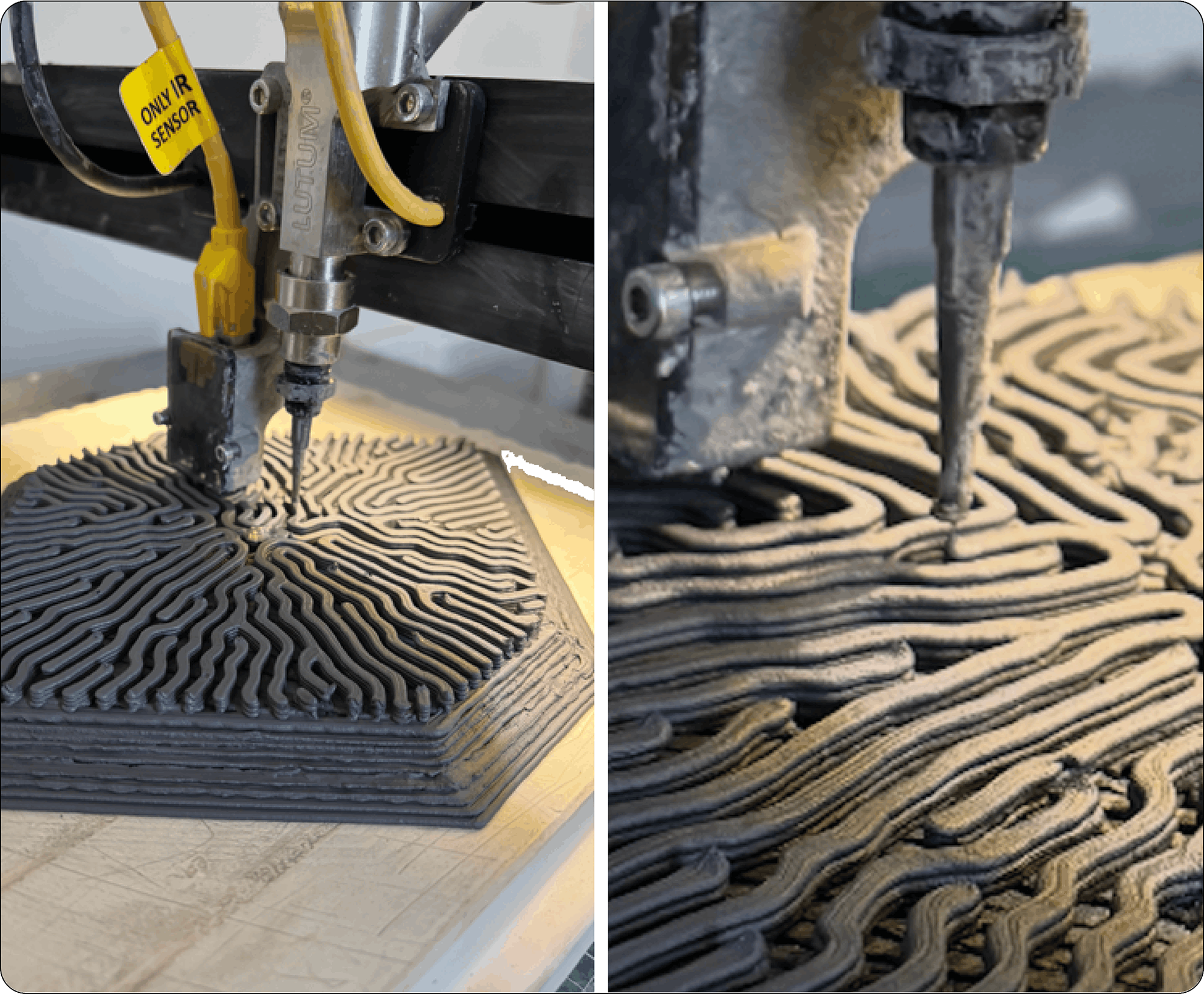
Geometry of the clay models were developed in AutoCad and Rhinoceros 3D, exported as STL files and processed using PrusaSlicer, following a workflow adapted for paste-extrusion clay printing. The LUTUM 5 printer was equipped with a 3 mm nozzle, with print speed set to 110% of the machine’s default profile and extrusion flow adjusted between 60–70% to stabilize bead width and layer adhesion. All clay panels shared a long hexagonal morphology; three nominal heights were used, approximately 144.13, 264.58 and 127.44 mm and each dimension was scaled 12% larger in the digital model to compensate for drying and firing shrinkage.
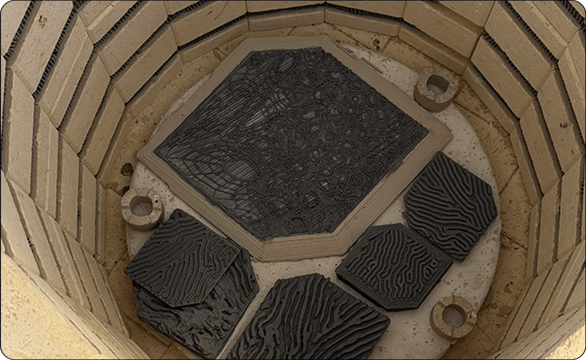
Figures 10 and 11 document the development of the clay fabrication workflow, from material preparation to the thermal transformation of the final prototypes. Figure 10 presents the evaluation of clay consistency for the extrusion-based 3D printing process using the LUTUM 5 printer, assessing the material’s printability, structural stability and capacity to retain complex surface geometries. Figure 11 shows the kiln firing process of the 3D-printed stoneware clay panels, highlighting the transition from raw printed components to durable ceramic prototypes suitable for bioreceptive applications.
Evaluating clay consistency for the 3D printing process on LUTUM 5 printer.

Kiln firing process of the 3D-printed clay panels (stoneware).

Biological inoculation and preliminary observations
The collection site, a pond at Sempione Park, was selected for its ecological relevance due to its proximity to the Milan Triennale. The water samples were collected in situ from the southeast side of the pond, where the intensity of the greenish water colour indicated higher algal concentrations. Sampling focused on the surface layer, where light and oxygen availability promote microbial growth.
Biological component
The undefined mixed culture was placed in six plastic boxes, supplemented with a nutrient solution and exposed to UV LED light for six hours. All of the panels were then immersed in these inoculation baths for a minimum of ten hours.
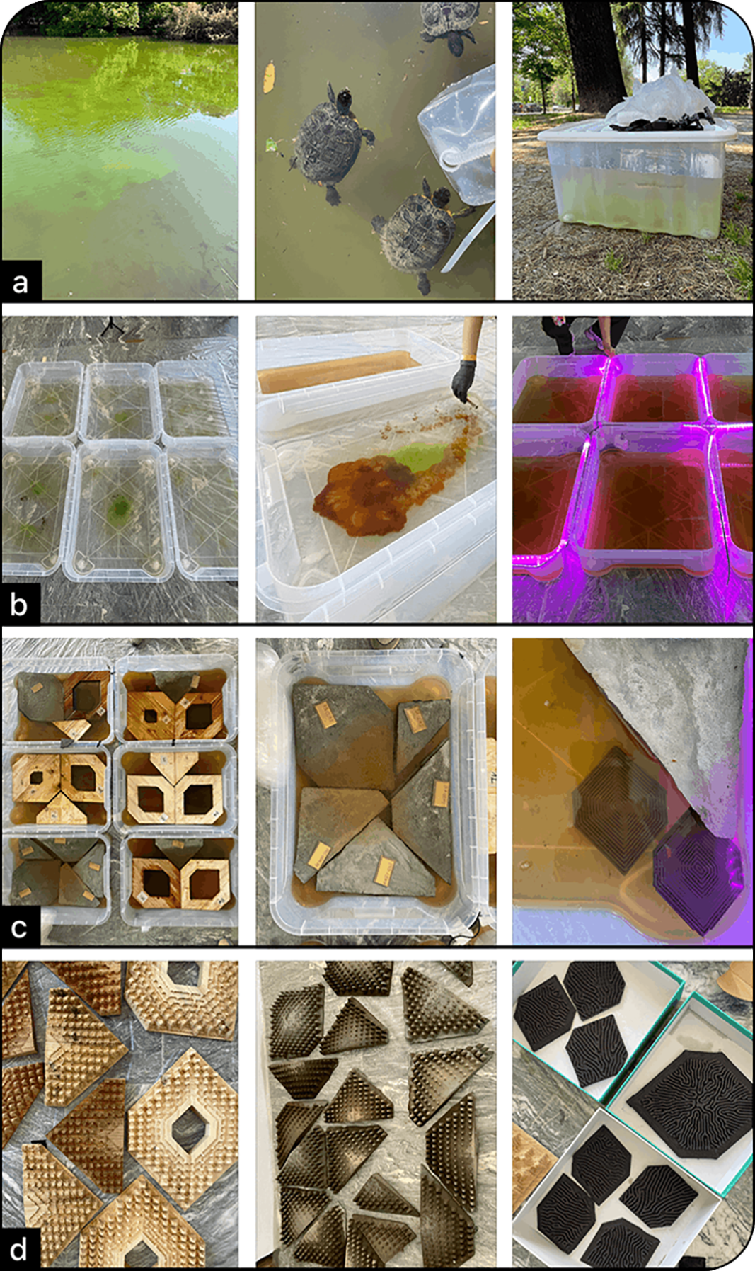
Figure 13 details the collection and inoculation process of the cryptogamic–microbial inoculum applied to the different panels. The inoculum was collected from pond water at Parco Sempione, in the vicinity of the Triennale Milano (a). Subsequently, soaking baths were prepared with nutrient solutions and LED lighting to promote microbial activity and growth (b). The panels were then immersed in the inoculum baths for approximately 15 hours to ensure effective colonization of the surface (c). Following inoculation, the panels were maintained under semi-controlled conditions through regular water spraying to support the establishment and development of the cryptogamic–microbial communities (d).
Comparative summary of fabrication methods, material properties relevant to bioreceptivity and geometric outcomes.

Figure 12. Long description
A comparative table summarizing the fabrication methods used for wood, concrete, and clay components, including the key fabrication parameters, material properties relevant to bioreceptivity, such as porosity, pH, and surface roughness, and the geometric outcomes achievable with each material. The table compares CNC-milled wood samples, mould-cast concrete samples, and 3D-printed clay samples, highlighting the capabilities and limitations of each fabrication technique for the production of bioreceptive architectural components.
Cryptogamic-Microbial inoculum collection and inoculation process on the different panels: (a) collection from pond water at Parco Sempione, Milan Triennale Park. (b) Baths set-up with nutrient and LEDs lighting. (c) Inoculation of the panels in soaking baths for 15 hours. (d) Maintenance of the panels with water spray after the inoculation.

After seventy-five days, all substrates – wood, concrete and clay – exhibited initial biological growth, indicating promising colonization. However, due to the constraints of the exhibition setting, no quantitative monitoring (e.g., percentage coverage, species identification via microscopy or DNA barcoding, chlorophyll fluorescence measurements) was performed. The observations reported here are therefore qualitative and visual.
SPIKA installation
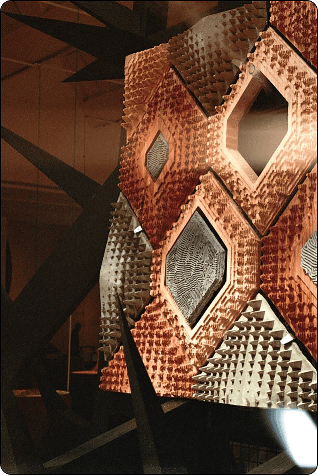
The installation of the panels adhered to the architectural logic of the SPIKA composition, with the panels systematically distributed across the four vertical façades of the structure (Armstrong, Reference Armstrong2025; Modesto et al. Reference Modesto, Ogun Ramalhete, Ravasi, Pezzoli, Sharma, Nath, Yücel, Moons, Melcore, Vershinina, Tait, Ogunmefun, Reutina, Colliaux, Baquedano Mozos, Willey, Ieropoulos, Cristiani, Hanappe, Barriuso, Schmidt and Armstrong2026). Each façade accommodated seven concrete panels, seven wooden panels and three clay panels. This spatial configuration was intentionally designed to reflect not only the aesthetic composition but also the indoor environmental exposure conditions. Panel positioning accounted for variables such as solar orientation, which was expected to influence biological growth processes over the duration of the exhibition.
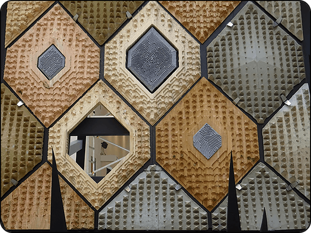
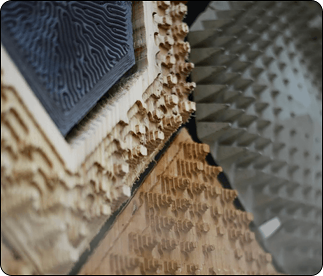
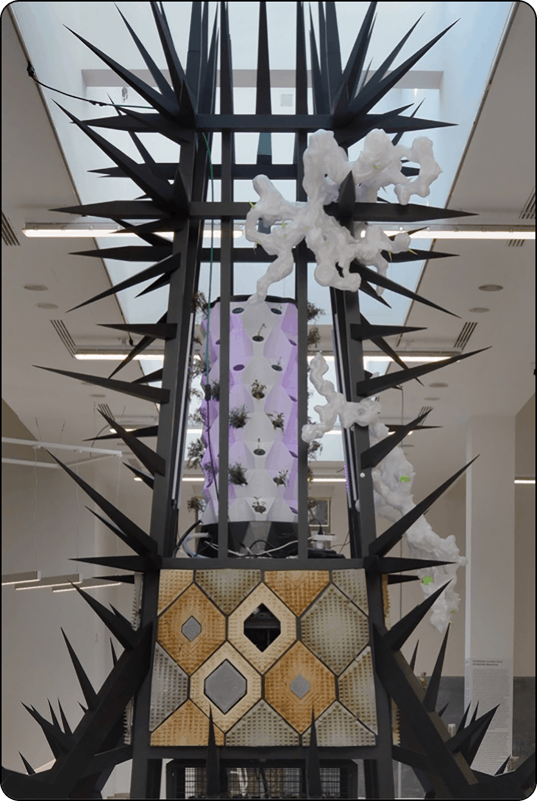
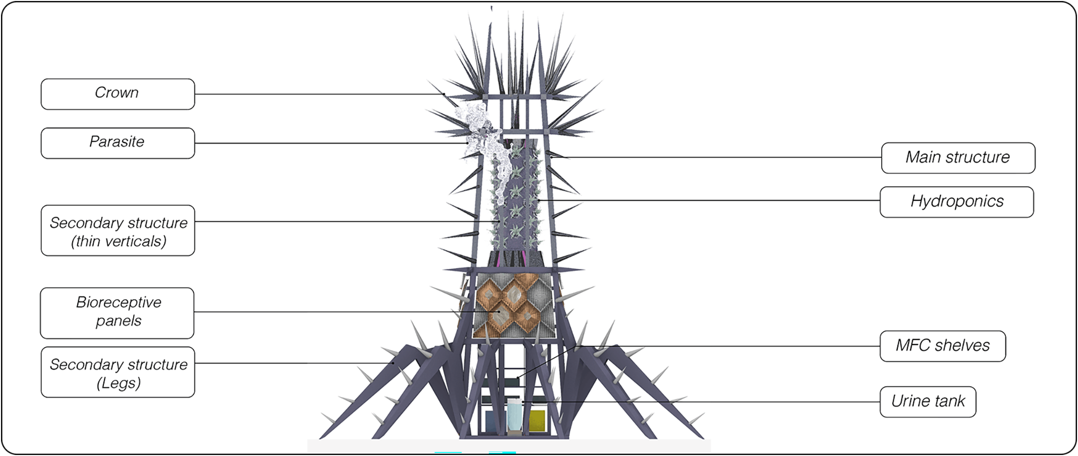
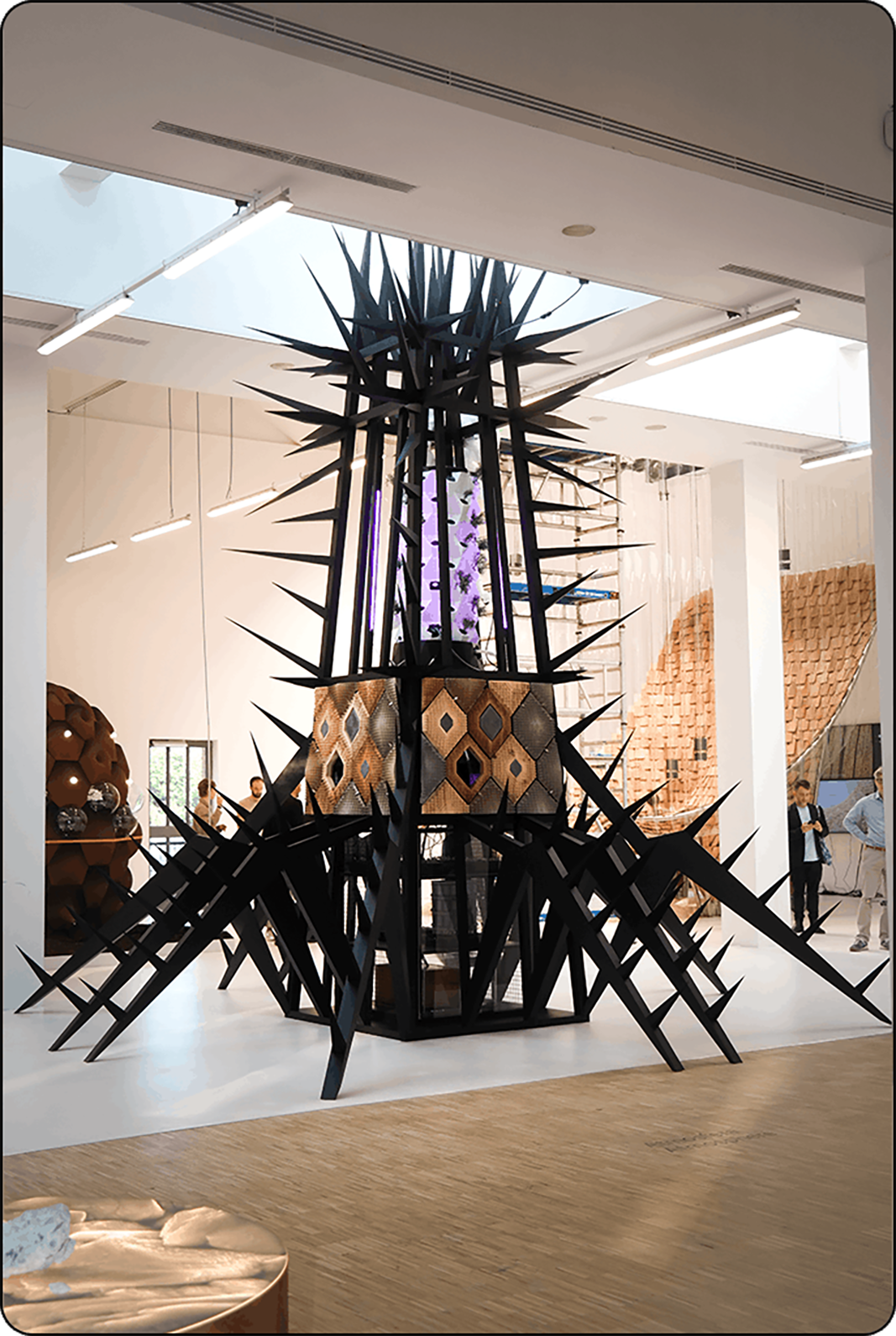
Figures 15–20 present the SPIKA installation within the Microbial-Hydroponics (Mi-Hy) project, presented as part of the exhibition “Inequalities. We the Bacteria. Notes Toward Biotic Architecture” at Milano Triennale in 2025. Together, the images illustrate the spatial and material organization of the bio-receptive system, from the integration of panel tessellations within the broader biological garden (Figures 18 and 19). They further document the full-scale SPIKA prototype, where the bioreceptive panels system was deployed across four vertical façades, arranged in a structured modular grid (Figures 15–17). The four vertical façades of the structure each accommodated seven concrete panels, seven wooden panels and three clay panels. The south-facing façade received the highest solar exposure, while the north-facing façade received the least. Panel positions were recorded to allow future correlation with growth patterns, but the current study does not analyse orientation-dependent effects due to the absence of quantitative growth data. Figure 19 provides an overall frontal view of the installation, consolidating the system’s architectural assembly and its integration of bio-receptive surfaces within a coherent experimental structure.
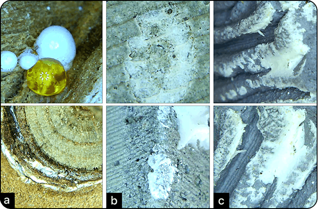
Initial biological growth observed across the different substrates after a two-month period: (a) wood, (b) concrete and (c) clay. 20× magnification. Annotations: On the wood samples (a), whitish nodular formations and biofilm development are observable along the natural wood grain. On the concrete samples (b), patchy white colonies appear preferentially on rougher cast surfaces, suggesting localized surface conditions favourable to biological attachment. On the clay samples (c), filamentous whitish growth follows the layered deposition patterns generated through the 3D-printing process. Samples were collected from the north-facing side of the installation, where solar exposure and light was lowest. As no longitudinal or time-series documentation was conducted during the growth period, the images presented here should be considered endpoint observations only.

Bio-receptive panels tessellation as part of the overall biological garden in the SPIKA installation (Microbial-Hydroponics [Mi-Hy] project). Photograph by Rachel Armstrong during the exhibition “Inequalities. We the Bacteria. Notes Toward Biotic Architecture,” Milan Triennale, 2025.

Figure 15. Long description
An image showing an extract of the completed bioreceptive panel tessellation integrated into the SPIKA installation at the Milan Triennale 2025. This section of the installation comprises a total of 17 modular panels, including seven CNC-milled wood panels, seven mould-cast concrete panels, and three 3D-printed clay panels.
Surface patterning details of the bio-receptive panels tessellation. Photograph by BioFaction team.

Surface patterning details of the bio-receptive panels tessellation. Photograph by Işıl Yücel. Milan Triennale, 2025.

SPIKA overall prototype setup of the Mi-Hy system, including the series of bio-receptive panels. Photograph by Işıl Yücel. Milan Triennale, 2025.

Figure 18. Long description
A photograph of the upper section of the SPIKA installation, a seven-meter-tall structure showcasing the Mi-Hy system and its ecological and functional components. The image features a 3D-printed parasite component, a hydroponic tower supporting plant growth, and bioreceptive panels fabricated from wood, concrete, and clay. The structure is topped with black spikes approximately 1 m in height, inspired by defensive natural morphologies, consistent with the biomimetic spiky surface patterns used in the bioreceptive panels.
SPIKA diagram showcasing the vertical garden and its ecological and functional components.

Figure 19. Long description
A diagram of the front view of the SPIKA installation showcasing the vertical garden and its ecological and functional components. The diagram illustrates the main structure of the installation, the secondary built structure, the leg substructure inspired by bacteriophage morphology, the spiky crown, the 3D-printed parasite component, the hydroponic tower, the bioreceptive panels, the MFC section, and the urine tank supplying the system, all working together as one integrated system.
Front view of SPIKA, a 7-metre-tall installation, showcasing the overall prototype setup of the Mi-Hy system. Photograph by Işıl Yücel during the exhibition “Inequalities. We the Bacteria. Notes Toward Biotic Architecture,” Milan Triennale, 2025.

Figure 20. Long description
An image of the final SPIKA installation integrating all components of the Mi-Hy system. The installation is presented within the Microbial-Hydroponics (Mi-Hy) project, as part of the exhibition Inequalities. We the Bacteria. Notes Toward Biotic Architecture at the Milan Triennale in 2025.
Conclusion
SPIKA demonstrates an exploratory integration of computational design, parametric fabrication and ecological inoculation within an unified architectural installation. By comparing subtractive, formative and additive manufacturing methods across wood, concrete and clay substrates, the project qualitatively documents that diverse fabrication paradigms can support initial biological colonization under indoor environmental conditions. The observed initial growth across all material types validates the proposed design-to-fabrication workflow as a replicable model for future, more controlled studies of bio-receptive architecture.
Limitations and future work
This study does not claim to be a controlled comparative analysis of biological performance. Key limitations include: (1) no quantitative measurement of colonization (e.g., % coverage, species identification, biomass), (2) no replication or statistical treatment, (3) no isolation of morphology from other variables (porosity, pH, material chemistry) and (4) no time-series monitoring. Future work will involve laboratory-controlled experiments with standardized inocula, replicate samples and systematic measurement protocols. Additionally, the relationship between specific geometric features (spike density, curvature, layer-line orientation) and colonization success requires dedicated parametric variation studies.
Reconceptualizing façades as dynamic ecological interfaces, SPIKA offers a transferable pathway toward regenerative design practices that actively support urban biodiversity and ecological succession, while recognizing that rigorous quantitative validation remains the necessary next step.
Data availability statement
The authors confirm that the data supporting the findings of this study are available within the article.
Acknowledgements
The authors would like to thank: Beatriz Colomina and Mark Wigley, curators of the 24th International Exhibition “Inequalities. We the Bacteria. Notes Toward Biotic Architecture” for inviting the RAAD research group to showcase its work at the Milan Triennale from May 13 to November 9, 2025; Maurizio Bisi (Medbcreateam Srl) and his entire construction team for their support during the installation’s construction.
The Microbial-Hydroponics (Mi-Hy) research team for their guidance and collaboration, including Prof. Yannis Ieropoulos and Natasha Tait (University of Southampton, UK), Prof. Peter Hanappe and Dr. Lenon Romano (Sony Computer Science Laboratories, Paris, France), Prof. Jorge Barriuso and Dr. Ignacio Barriuso (Spanish National Research Council, Madrid, Spain), Prof. Markus Schmidt, Uliana Reutina, Camillo Meinhart and Ines Sarazin (BioFaction, Vienna, Austria) and Prof. Neil Willey and Dr. Mukesh Sharma (University of the West of England, Bristol, UK).
Milan Polytechnic University (Politecnico di Milano) for facilitating this research, including Prof. Valentina Rognoli (Department of Design), Dr. Salvatore Viscuso, Dr. Anna Dalla Valle and Lorenzo Rota (Department of Architecture, Built Environment and Construction Engineering, DABC).
Mahsa Davaraza, Ph.D. exchange researcher, for her advice on clay 3D printing (University of Aveiro, Department of Environment and Planning, Aveiro, Portugal).
All technicians from LUCA School of Arts (Campus Sint-Lucas, Brussels and Ghent, Belgium) who contributed to prototyping the panels: Robin Berrewaerts, Sam Van Gils, Bart Aertsen, Ambet Manalo and Elie Desmet (Wood Workshop, LUCA Construct); Glenn De Cock, Julia Hadassa Cumaru and Amy Beaulisch (LUCA 3D Printing) and Sabine Deroo (LUCA Ceramics).
Author contributions
Conceptualization: Marie Melcore, Anna Vershinina, Işıl Yücel and Rachel Armstrong. Methodology: Marie Melcore, Anna Vershinina, Işıl Yücel and Ezgi Öğün Ramalhete. Data curation: Ezgi Öğün Ramalhete. Visualization: Marie Melcore, Anna Vershinina and Işıl Yücel. Writing – Original draft: Marie Melcore (initial manuscript draft); Anna Vershinina (subsection 2, Formative Manufacturing: Mould-Casting); Işıl Yücel (subsection 2, Additive Manufacturing: 3D Printing). Writing – Review and editing: Rachel Armstrong.
Financial support
This research was supported by the European Union’s Horizon Europe EIC Pathfinder Challenges research and innovation program through the Mi-Hy project (Grant Agreement No. 101114746); the Bio+Wood FWO Junior Research Project; and the Bio+Concrete FWO Doctoral Fellowship. This work was additionally facilitated by an Erasmus award between KU Leuven and Milan Polytechnic and supported by Johan Verbeke Belgium funding.
Competing interests
The authors declare that this work was conducted in the absence of any commercial or financial relationships that could be construed as a potential conflict of interest.
Ethics standards
The authors declare that no ethical approval was required for this study as it did not involve human or animal subjects.

 Open access

