





Impact statement
Floating offshore wind energy is an important opportunity for increasing the production of renewable electricity, especially in deep-water areas where winds are stronger and more consistent. However, floating wind turbines must operate safely in a challenging marine environment, where waves can strongly influence platform motions and the loads acting on the mooring system. This study provides useful insight into how numerical modelling can support the preliminary design of floating offshore wind structures. By simulating the response of a spar-buoy platform under different wave conditions, the work helps identify how design choices, such as the position of the centre of mass, can affect stability and structural performance. The results show that careful adjustment of the platform mass distribution can improve the overall behaviour of the system, reducing structural motions while having a more limited influence on the forces transmitted to the mooring lines. At the same time, the study highlights that no single configuration is optimal for every aspect of performance, since improving one response may affect another. Finally, the work demonstrates the value of advanced computational tools for testing floating wind concepts before costly experimental or full-scale applications. This can help engineers make better design decisions, reduce risks and support the development of safer and more efficient floating offshore wind technologies.
Introduction
The transition towards low-carbon energy systems has increased interest in offshore wind energy, which is considered one of the most promising technologies for large-scale renewable power generation. Offshore wind farms can exploit stronger and more persistent wind resources than those available onshore, while reducing land-use constraints and visual impact. However, most commercial installations still rely on bottom-fixed foundations, whose feasibility is generally limited to shallow waters. As suitable shallow-water sites become progressively saturated, floating support structures are becoming essential for extending offshore wind deployment to deep-water areas (Edwards et al., Reference Edwards, Holcombe, Brown, Ransley, Hann and Greaves2023; International Renewable Energy Agency, 2024). Floating Offshore Wind Turbines (FOWTs) represent a key enabling technology for this expansion, since they allow wind energy to be harvested where conventional fixed foundations are no longer practical. Several floating concepts have been proposed, including spar-buoy, semi-submersible, tension-leg and barge-type systems, each characterised by different stability mechanisms, hydrodynamic behaviour and mooring requirements (DNV, 2025). Among these, steel spar-buoy platforms are attractive for deep-water applications because of their better hydrostatic stability and simple structural layout. Nevertheless, their dynamic response strongly depends on the mass distribution, position of the centre of gravity, restoring characteristics and interaction with the mooring system. Compared with bottom-fixed turbines, FOWTs introduce additional modelling and design challenges. The platform, turbine and mooring system form a coupled dynamic system subjected to wind, waves, currents and restoring forces. These loads may generate significant six-degree-of-freedom (6DOF) motions, affecting platform stability, turbine performance, fatigue loads and mooring line tensions. Therefore, accurate prediction of platform motions and hydrodynamic loads is a central aspect of the preliminary design process (Butterfield et al., Reference Butterfield, Musial, Jonkman and Sclavounos2007; Otter et al., Reference Otter, Murphy, Pakrashi, Robertson and Desmond2022; DNV, 2025). Numerical modelling provides a bridge between simplified theoretical formulations, experimental investigations and full-scale engineering applications. Although physical model tests remain essential for validation, they are affected by scale effects and require expensive, time-consuming campaigns. Numerical simulations allow floating systems to be analysed in a controlled environment and under a wide range of operating and extreme sea states.
Different numerical tools are adopted depending on the required level of detail, computational cost and design stage. Different numerical approaches have been developed to investigate wave-structure interaction and the dynamic response of floating offshore systems, with different levels of physical detail and computational requirements. Low- and medium-fidelity engineering tools are extensively employed for the analysis of floating structures, particularly when a large number of environmental conditions must be considered. OpenFAST (Jonkman et al., Reference Jonkman, Mudafort, Platt, Branlard, Sprague, Jonkman, Hayman, Vijayakumar, Buhl, Ross, Bortolotti, Masciola, Ananthan, Schmidt, Rood, Mendoza, Hai, Hall, Sharma, Shaler, Bendl, Schuenemann, Sakievich, Quon, Phillips, Kusouno, Gonzalez Salcedo, Martinez and Corniglion2022), for example, provides a coupled framework in which the hydrodynamic response of a floating platform can be combined with aerodynamic, structural, control and mooring models. Similar analyses can be performed using QBlade, while commercial tools such as OrcaFlex and ANSYS AQWA are widely employed for hydrodynamic and time-domain analyses of floating offshore structures and mooring systems (Lauria et al., Reference Lauria, Loprieno, Rizzo, Severini, Foti, Leone, Francone and Tomasicchio2024). These approaches generally rely on potential-flow theory or Morison-type formulations and represent established tools for assessing the global response of floating systems. They have also been employed to investigate passive response-control strategies for FOWTs, including tuned mass and tuned liquid column dampers (Han et al., Reference Han, Li, Wang and Su2025).
At a higher level of hydrodynamic resolution, grid-based Computational Fluid Dynamics (CFD) methods have been increasingly applied to a broad range of floating structures. OpenFOAM® has been extensively used in this field, with applications ranging from floating offshore wind turbines to wave energy converters, floating breakwaters and generic moored bodies. For FOWTs, Zhang and Kim (Reference Zhang and Kim2018) investigated the coupled response of a semi-submersible floating wind turbine under combined wind and wave excitation, considering the interaction between aerodynamic loads and platform hydrodynamics. Moving from complete FOWT systems to more general floating-body problems, Chen and Hall (Reference Chen and Hall2022) analysed a floating box restrained by four catenary mooring lines under regular waves, focusing on platform motions and mooring tensions and validating the numerical response against experimental measurements. The same CFD framework has also been applied to floating wave energy devices. In particular, Khan et al. (Reference Khan, Barajas, Gaeta, López Lara and Archetti2024) investigated a cylindrical floating WEC equipped with a moonpool, using experimental data and CFD simulations to assess the influence of the device mass properties on heave and pitch response and to support the hydrodynamic optimization of the system.
Grid-based CFD has also been employed for floating coastal structures, where the objectives extend beyond the prediction of body motion to the evaluation of wave attenuation and structural performance. Chen et al. (Reference Chen, Zhang, Wang, Zhang, Guo and Sun2022) investigated box-type floating breakwaters under long-period waves, analysing the influence of draft, breakwater dimensions, spacing and mooring properties on wave transmission and dissipation. More recently, Chen et al. (Reference Chen, Almeida Medina and Cercos-Pita2024) extended this type of analysis to multiple moored floating structures, considering both single and twin floating breakwaters and evaluating their coupled dynamic response under wave loading. These applications illustrate how CFD-based numerical wave tanks are increasingly used not only to reproduce the motion of an isolated floating body, but also to investigate the influence of structural configuration, mass distribution, mooring characteristics and interactions between multiple floating elements.
Grid-based analyses of floating structures have also been developed using commercial CFD solvers. STAR-CCM+ and ANSYS Fluent have been employed for different applications involving wave-induced body motions and hydrodynamic loading. Dell’Edera et al. (Reference Dell’Edera, Niosi, Casalone, Bonfanti, Paduano and Mattiazzo2024) used STAR-CCM+ to validate two different moored floating wave energy converters against experimental measurements, considering body kinematics, mooring tensions and pressure distributions around the floaters. ANSYS Fluent has also been applied to freely floating bodies subjected to nonlinear wave conditions. Gao et al. (Reference Gao, Wang, Su and Chen2019) investigated the large-amplitude response of a floating box subjected to focused waves. More recently, Gil et al. (Reference Gil, Armañanzas, Torres, Fuertes, Campaña, Mendez and Leon2025) compared high-fidelity CFD approaches with a potential-flow model for full-scale floating-platform free-decay simulations. Commercial CFD tools therefore provide an alternative framework for detailed analyses of floating systems, with applications ranging from renewable energy devices to more general offshore and coastal structures, although their proprietary and closed-source nature may limit accessibility, transparency and the possibility of directly modifying the underlying numerical implementations compared with open-source frameworks.
Alongside grid-based approaches, mesh-free methods have also been increasingly applied to wave-floating-body interaction. Among these, Smoothed Particle Hydrodynamics (SPH) has been used for a variety of floating configurations and hydrodynamic problems. He et al. (Reference He, Liang, Ren, Li and Shao2023) investigated wave interaction with a moored multi-float structure composed of flexibly connected modules, considering the relative motion of the individual bodies, mooring forces and mechanical interactions between adjacent elements. For floating wind applications, Tan et al. (Reference Tan, Sun, Liu, Li, Lyu and Zhu2023) studied the dynamic response of floating systems under wave loading and validated the numerical model against experiments involving both a floating box and a scaled FOWT. Similarly, Tagliafierro et al. (Reference Tagliafierro, Karimirad, Altomare, Göteman, Martínez-Estévez, Capasso, Domínguez, Viccione, Gómez-Gesteira and Crespo2023) investigated a semi-submersible platform under different wave conditions, including regular, irregular and nonlinear waves. SPH has also been applied to moored floating platforms with different moonpool configurations (Zou et al., Reference Zou, Zhao, Sun, Sun, Luo and Yu2024) and to the interaction between floating platforms and extreme freak waves (Cai et al., Reference Cai, Yang, Luo and Khayyer2024). In addition, Altomare et al. (Reference Altomare, Gironella and Crespo2021) applied the DualSPHysics (Domínguez et al., Reference Domínguez, Fourtakas, Altomare, Canelas, Tafuni, García-Feal, Martínez-Estévez, Mokos, Vacondio, Crespo, Rogers, Stansby and Gómez-Gesteira2022) model to investigate random wave overtopping of a dike-promenade system, validating the numerical results against physical model tests. These applications show that particle-based methods are increasingly employed for a broad range of coastal and offshore problems involving nonlinear free-surface dynamics and complex wave-structure interactions.
Within the grid-based CFD framework adopted in the present work, OpenFOAM® provides the required capabilities to reproduce wave propagation, six-degree-of-freedom body motion and the interaction between the floating platform and the mooring system. A relevant numerical aspect in this context is the treatment of body motion and the associated evolution of the computational grid. Mesh morphing can be adopted when body displacements remain compatible with an acceptable deformation of the surrounding cells, whereas alternative moving-grid strategies can be employed when larger motions are expected (Windt et al., Reference Windt, Davidson, Chandar, Faedo and Ringwood2020). In the present study, mesh morphing and overset approaches are therefore considered under different wave conditions to assess their applicability to the hydrodynamic analysis of the investigated spar-buoy platform.
Objectives and outline of the work
The present study investigates the hydrodynamic response of a spar-buoy floating offshore wind platform using OpenFOAM® v. 2406. The analysis focuses on the influence of the centre of mass (CoM) position on the dynamic behaviour of the platform, since variations in the mass distribution can significantly affect the inertial properties, restoring response and overall stability of the floating system. In addition, mesh morphing simulations are compared with an overset mesh approach for a more severe wave-loading condition, where larger body motions may challenge the applicability of purely deforming-grid techniques.
The present work is structured as follows. Section “Methods” describes the methodology adopted in this study, distinguishing between the experimental and numerical approaches. In Section “Results and discussion,” the numerical results are then presented and discussed according to the adopted numerical method, namely mesh morphing and overset mesh techniques. Finally, in Section “Conclusion,” the main findings and conclusions are summarised, and future developments are also outlined.
Methods
The numerical framework builds on the modelling approach adopted in Lauria et al. (Reference Lauria, Loprieno, Rizzo, Severini, Foti, Leone, Francone and Tomasicchio2024) for the same OC3-Hywind platform, and is independently verified and validated in Section “Numerical validation” against the experimental campaign carried out by Russo et al. (Reference Russo, Contestabile, Bardazzi, Leone, Iglesias, Tomasicchio and Vicinanza2021).
Experimental setup
The experimental campaign was performed on a three-dimensional small physical model of a floating offshore wind turbine operating in deep-water conditions, with a water depth equal to 6 m, and subjected to incident regular and irregular wave loading. The tested configuration reproduces, at a Froude scale of 1:40, the OC3-Hywind (Jonkman, Reference Jonkman2010) spar-buoy concept. The floating platform consists of two main cylindrical sections connected through a conical transition element. The upper cylinder has a height of 0.4 m and an outer diameter of 162.5 mm, whereas the lower cylinder is 2.6 m high with an outer diameter of 235 mm. The two portions are connected by a conical section with a length of 0.2 m. At the base of the structure, a removable ballast element with a height of 0.1 m is installed and filled with lead in order to achieve a total draft of 3 m and position the CoM of the floating body 2.25 m below the still water level (SWL).
The floating support structure is equipped with the reference US National Renewable Energy Laboratory (NREL) 5 MW wind turbine (Jonkman et al., Reference Jonkman, Butterfield, Musial and Scott2009), which is widely employed in both experimental campaigns and numerical investigations involving floating offshore wind systems. The adoption of this reference turbine ensures consistency with previous studies and provides a reliable benchmark for aero-hydro-servo-elastic analyses. The mooring system consists of three mooring lines symmetrically distributed around the platform with an angular spacing of
$ 120{}^{\circ} $
 , keeping the incident wave direction perpendicular to the turbine rotor plane. With respect to the wave propagation direction (
$ x $
 -axes, Figure 1), the Mooring Line 1 is aligned with the incoming wave direction, whereas the Mooring Lines 2 and 3 are inclined by
$ 60{}^{\circ} $
 . Each mooring line is equipped with a dedicated load cell in order to measure the tensions transmitted to the floating platform during the experimental campaign.
Side and plan views of the investigated platform, showing the three CoM configurations and the mooring-line arrangement.

Figure 1 Long description
Figure 1 shows side and plan views of the investigated spar-buoy platform. Three centre-of-mass configurations are indicated along the vertical axis. The plan view shows three mooring lines arranged symmetrically at 120 degrees around the platform, with line 1 aligned with the wave direction and lines 2 and 3 inclined symmetrically.
The experimental measurements provide a detailed characterisation of the dynamic behaviour of the system under wave action. In particular, the platform response was analysed in terms of translational motions along the three principal directions (
$ x $
 ,
$ y $
 ,
$ z $
 , Figure 1), namely surge, sway and heave, respectively, together with the rotational motions around the corresponding axes, namely roll, pitch and yaw. These measurements constitute the reference dataset employed to validate the numerical model and to assess its capability to reproduce the 6DOF response of the floating platform.
Numerical framework
The numerical framework is based on the solution of the Reynolds-Averaged Navier–Stokes equations, coupled with a Volume of Fluid (VOF) formulation to describe the evolution of the free surface between two immiscible phases, namely water and air. This modelling strategy allows the main features of the wave-structure interaction problem to be captured, including the propagation of the incident wave field, the motion of the air-water interface and the hydrodynamic loads acting on the floating body. The governing equations consist of the mass conservation equation and the momentum conservation equation, expressed as Equations (1) and (2):


where
$ \rho $
 is the fluid density,
$ \mathbf{u} $
 is the velocity vector,
$ p $
 is the pressure,
$ {\mu}_{\mathrm{eff}} $
 is the effective viscosity,
$ \mathbf{g} $
 is the gravitational acceleration,
$ t $
 is the time and
$ {\mathbf{f}}_{\sigma } $
 represents the surface tension contribution. In OpenFOAM, this term is evaluated from the local curvature of the air–water interface, together with the prescribed surface tension coefficient. For the characteristic length scales considered in the present study, surface tension effects are expected to be small compared with gravitational effects and, therefore, to have a negligible influence on the global platform response, although the term is retained in the governing equations. The air–water interface is tracked through the VOF with the transport equation of the volume fraction, Equation (3):

where
$ \alpha $
 denotes the water volume fraction and
$ {\mathbf{u}}_r $
 is an artificial compression velocity, active only in the interface region, which counteracts numerical smearing. Values of
$ \alpha =1 $
 and
$ \alpha =0 $
 identify cells fully occupied by water and air, respectively, while intermediate values define the free surface region.
The governing equations are discretised with the finite volume method on a collocated, unstructured grid. Time integration is performed with a first-order implicit Euler scheme, with an adjustable time step limited by the maximum Courant number, set equal to 0.5. The adopted threshold lies below the stability limit of the explicit MULES algorithm and is consistent with the recommendations of Larsen et al. (Reference Larsen, Fuhrman and Roenby2019) for wave propagation in interFoam. Convective terms in the momentum equation are discretised with a second-order linear-upwind scheme with a cell-limited gradient, which prevents spurious velocity overshoots in the most distorted cells. The turbulence equations were solved with a first-order upwind scheme, the volume fraction with the compressive van Leer scheme and diffusive terms with limited non-orthogonal correction. Pressure–velocity coupling is solved with the PIMPLE algorithm, using four outer correctors per time step with the grid updated at each iteration and an under-relaxation factor of 0.5 on the rigid-body acceleration, to prevent added-mass instabilities.
Turbulence is modelled with the
$ k $
 -
$ \omega $
 SST closure, combined with the formal stabilisation proposed by Larsen and Fuhrman (Reference Larsen and Fuhrman2018). Standard two-equation closures are unconditionally unstable in the nearly potential flow region beneath non-breaking waves, where the turbulent kinetic energy and the eddy viscosity grow exponentially, resulting in an excessive damping of the propagating waves (Devolder et al., Reference Devolder, Rauwoens and Troch2017; Larsen and Fuhrman, Reference Larsen and Fuhrman2018). They showed that, for high-steepness regular waves with a wave steepness of ~0.07, comparable to the upper range considered in the present study, the standard
$ k $
 -
$ \omega $
 SST model can lead to a substantial reduction in wave height along the numerical flume, between 40% and 50%, while the modified formulation largely preserves the incident wave amplitude. The stabilised formulation is therefore particularly relevant for the present simulations, in which the incident waves propagate over two wavelengths before reaching the platform, since excessive numerical dissipation during propagation could modify the wave height and consequently affect the hydrodynamic loading acting on the structure.
In the first stage, the motion of the floating platform is handled using a mesh morphing strategy, following the approach adopted in previous OpenFOAM-based studies on floating-body dynamics (Chen and Hall, Reference Chen and Hall2022; Palm and Eskilsson, Reference Palm and Eskilsson2022). In this method, the computational grid is not regenerated at each time step, but is, instead, continuously deformed according to the rigid-body motion of the structure. The 6DOF displacements of the platform are used as inputs for the mesh deformation procedure, while the magnitude of the mesh motion gradually decreases with the distance from the floating body. This allows the cells located close to the structure to follow its motion, while the outer regions of the domain remain almost unaffected. The mesh deformation of the model is performed using a spherical linear interpolation procedure, which provides a smooth transition of the displacement field and helps to preserve the quality of the computational grid during the simulation (Shoemake, Reference Shoemake1985). In this approach, the mesh motion is controlled according to the distance from the moving body. Mesh points located within a prescribed inner distance from the platform follow the full rigid-body motion, whereas points located beyond an outer distance remain fixed. In the intermediate region, the imposed translation and rotation are progressively reduced using a smooth distance-based weighting function. This approach preserves the mesh topology without requiring remeshing and limits local cell distortion as long as the body motion remains moderate. However, as the platform motion increased, the mesh deformation became progressively more severe, and under the highest wave condition, excessive cell distortion eventually led to numerical instability, motivating the use of an alternative strategy for the most demanding wave condition. For the extreme sea state, where the platform motions exceed the deformation that the mesh morphing algorithm can accommodate without excessive grid distortion, the body motion is instead handled using the overset mesh method, natively available in OpenFOAM®. In this approach, the computational domain is composed of two independently generated, overlapping meshes: a background mesh, spanning the full computational domain and fixed in space, and an inner mesh, containing the floating platform, which moves rigidly with the body. At each time step, the flow field is interpolated between the two meshes in the overlap region using a cell-volume-weighted scheme, which reconstructs each interpolated cell value from a volume-weighted average of the donor cells in the other mesh. Unlike mesh morphing, this method avoids cell deformation during the simulation, thereby preserving the quality of the individual meshes provided that an adequate overlap region is maintained.
The computational domain is defined so as to reproduce the main geometrical characteristics of the reduced-scale experimental facility. For the mesh morphing simulations, it consists of a total length of 23 m in the
$ x $
 direction (
$ -8 $
 m to
$ 15 $
 m), 8 m in the
$ y $
 direction and 14 m in the
$ z $
 direction (
$ -7 $
 m to
$ 7 $
 m), with the floating structure positioned close to the domain centre. A reference mesh is initially defined on the basis of the characteristic dimensions of the computational domain, the geometry of the floating structure and the spatial resolution required to describe the wave field. The background mesh is initially defined based on common meshing practices adopted in previous OpenFOAM studies of wave-floating-body interaction (Windt et al., Reference Windt, Davidson, Chandar, Faedo and Ringwood2020; Chen and Hall, Reference Chen and Hall2022). It is generated using characteristic cell dimensions of
$ 0.25 $
 m,
$ 0.50 $
 m and, within a graded vertical distribution,
$ 0.10 $
 m near the free surface, coarsening towards the top of the domain. In the region surrounding the floating structure, the grid is progressively refined using the native OpenFOAM utility snappyHexMesh, so that the cell dimensions progressively decrease towards the body. An additional refinement region is introduced around the free surface, extending vertically from
$ z=-1.6 $
 m to
$ z=0.35 $
 m, in order to provide an adequate representation of the wave kinematics and reduce numerical dissipation during wave propagation. The adequacy of this reference discretisation is assessed through the grid-convergence analysis described in Section “Numerical validation,” and the resulting mesh consists of ~0.98 million cells.
Following the parametric strategy adopted by Khan et al. (Reference Khan, Barajas, Gaeta, López Lara and Archetti2024), different inertial configurations of the floating system are investigated by varying the vertical position of the CoM. In particular, three configurations are analysed, in which the overall CoM of the turbine-platform system is placed at depths of 1.92, 1.82 and 2.02 m below the SWL, corresponding respectively to the dimensionless depth
$ {z}_{\mathrm{CoM}}/{z}_{\mathrm{floater}} $
 of 0.640, 0.607 and 0.673, as displayed in Figure 1. The first configuration corresponds to the reference case, while the other two are introduced to assess the sensitivity of the platform response to changes in mass distribution. The resulting platform motions and mooring-line tensions are then compared in order to evaluate the influence of the CoM position on the global dynamic response of the system and on the loads transmitted to the mooring system.
The dynamic response of the floating structure is analysed under regular, unidirectional wave conditions, reproducing the experimental sea states reported by Russo et al. (Reference Russo, Contestabile, Bardazzi, Leone, Iglesias, Tomasicchio and Vicinanza2021). Two wave tests are considered: WT1 with
$ H=0.13 $
 m and WT2 with
$ H=0.25 $
 m. For all tests, the wave period was kept constant at
$ T=1.6 $
 s and the simulated physical time was equal to 60 s.
In addition to the displacement analysis, the tensions induced in the three mooring lines are also assessed. For this purpose, the lumped-mass-based MoorDyn mooring model is adopted (Hall and Goupee, Reference Hall and Goupee2015). Each mooring line is discretised into a series of elastic segments connected by lumped-mass nodes. The model accounts for the axial stiffness and internal damping of the lines, submerged weight, hydrodynamic drag and added-mass effects, as well as seabed interaction when applicable. The motion of each node is governed by the following relation:

where
$ {\mathbf{M}}_i $
 is the effective mass matrix of the
$ i $
 -th node, including the added-mass contribution,
$ {\overset{"}{\mathbf{r}}}_i $
 is the node acceleration and
$ \sum {\mathbf{F}}_i $
 represents the total applied force, including line tension, internal damping, weight and buoyancy, hydrodynamic drag and seabed interaction. During the coupled simulations, the motion of the platform fairlead points is transferred to MoorDyn, while the resulting mooring forces return to the six-degree-of-freedom solver.
The LEONARDO supercomputer hosted by CINECA was employed for the simulations. An adjustable time-step strategy was adopted, with the maximum Courant number set to
$ {Co}_{\mathrm{max}}=0.5 $
 , selected as a compromise between numerical stability, temporal resolution and computational cost. The computational cost varies depending on the simulated wave conditions and the resulting platform motions; however, the dominant factor affecting the computational time is the adopted mesh-handling strategy. The mesh morphing simulations required ~5 h per test, using 192 MPI processes, while the overset simulations required ~18 h per test, reflecting the additional cost of the overset interpolation at each time step.
Numerical validation
The numerical model is validated by comparing the numerical results with the reference experimental data (Russo et al., Reference Russo, Contestabile, Bardazzi, Leone, Iglesias, Tomasicchio and Vicinanza2021). The comparison focuses primarily on the platform response in the six degrees of freedom in order to verify that the numerical model correctly reproduces the main physical mechanisms and dynamic behaviour observed in the experiments.
Prior to validation, the numerical model is subjected to a preliminary verification to assess its numerical performance and limit artificial numerical phenomena. This verification includes a grid-convergence study and an empty-tank wave-propagation test, focusing respectively on mesh sensitivity and wave-propagation accuracy.
A grid-sensitivity study is performed starting from the reference mesh described in Section “Numerical framework.” Three systematically refined grids containing ~0.44, 0.98 and 2.31 million cells are therefore considered, referred to as the coarse, intermediate and fine grids, respectively. A refinement ratio of ~
$ r=1.3 $
 is adopted between consecutive grids in each spatial direction. The convergence analysis is performed considering the platform surge and pitch responses, together with the upstream mooring-line tension. The results obtained with the coarse and intermediate grids are compared with those provided by the fine grid. The relative difference is evaluated as

where
$ {\phi}_i $
 represents the quantity obtained using either the coarse or intermediate grid, while
$ {\phi}_f $
 is the corresponding fine-grid value. Considering the peak values of the analysed quantities, the intermediate grid shows a considerably closer agreement with the fine-grid solution than the coarse grid for the platform motions. For surge, the relative difference with respect to the fine grid decreases from ~
$ 46.1\% $
 for the coarse grid to
$ 6.6\% $
 for the intermediate grid. Similarly, for pitch, the difference decreased from ~
$ 13.6\% $
 to
$ 1.6\% $
 . The upstream mooring-line tension exhibits a lower sensitivity to grid refinement, with relative differences of ~
$ 4.6\% $
 and
$ 4.2\% $
 for the coarse and intermediate grids, respectively. Most of the improvement is obtained already between the coarse and the intermediate grid, whereas further refinement yields comparatively diminishing returns. Although the fine grid remains the most accurate discretisation in principle, its use for the full simulation campaign would only be justified if it provided a comparable accuracy gain. The computational times associated with the coarse, intermediate and fine grids are ~2.6, 5.0 and 12.4 h, respectively. Given that the intermediate grid already agrees with the fine-grid solution within a few percent for all three quantities, and that its accuracy is independently confirmed against experimental measurements, the intermediate grid is retained for all subsequent simulations as the more efficient choice, with ~0.98 million cells for the mesh morphing simulations. Figure 2 shows the resulting background meshes for the mesh morphing (a) and overset (b) approaches, together with a detail of the refined region surrounding the platform, common to both meshing techniques (c).
Computational meshes adopted in the present study: (a) mesh morphing background mesh, lateral view; (b) overset background mesh, lateral view; (c) detail of the mesh in the vicinity of the platform, representative of both meshing techniques.

Figure 2 Long description
Figure 2 compares the computational meshes adopted for the two mesh-motion strategies. Panel (a) shows the mesh-morphing background mesh in lateral view. Panel (b) shows the overset background mesh in lateral view. Panel (c) shows the locally refined mesh around the platform, representative of both approaches, with increased resolution near the body and free surface.
Second, an empty-tank wave-propagation test, with no structure present, is carried out to verify the accurate propagation of the incident wave field and to quantify artificial numerical damping, which could otherwise influence the predicted six-degree-of-freedom motions of the structure. Regular waves (H = 0.13 m, T = 1.6 s) are considered within the scope. In such tests, the free surface resolution, as detailed in Section “Numerical framework,” is assessed, namely corresponding to ~5 cells per wave height in the vertical direction and 64 cells per wavelength in the horizontal direction. Although a vertical resolution of ~10 cells per wave height is commonly adopted in numerical wave tank simulations (e.g., Jacobsen et al., Reference Jacobsen, van, Capel and Borsboom2018; Chen et al., Reference Chen, Warmink, van Gent and Hulscher2021; Imbò et al., Reference Imbò, Scaravaglione, Saponieri, Lauria and Barajas2025), the selected resolution is retained to limit the computational cost, and its adequacy was assessed through the dedicated wave propagation test. With the free-surface refinement region extending from 1.6 m below to 0.35 m above the free surface, as adopted in the final mesh, the total discrepancy between the generated wave height, measured 7 m from the generation boundary, and the propagated wave height, measured two wavelengths further downstream at 15 m, was below
$ 5\% $
 , confirming that the selected resolution is adequate to reproduce wave propagation with limited numerical attenuation.
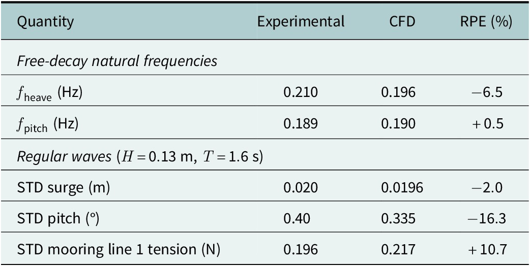
Building on the verified spatial discretisation and wave propagation accuracy described above, the numerical model is finally validated against the free-decay and regular-wave measurements reported by Russo et al. (Reference Russo, Contestabile, Bardazzi, Leone, Iglesias, Tomasicchio and Vicinanza2021). The natural frequencies from the free-decay tests are obtained from the oscillation period of the structure, while the response under regular waves is characterised using the standard deviation (STD) evaluated over the periodic steady-state window. The difference between the numerical model and the experimental measurements is quantitatively evaluated through the relative percentage error (RPE),
$ ({\phi}_{\mathrm{CFD}}-{\phi}_{\mathrm{exp}})/{\phi}_{\mathrm{exp}}\times 100 $
 . As shown in Table 1, the numerical model predicts natural frequencies of 0.196 Hz in heave and 0.190 Hz in pitch, compared with experimental values of 0.210 Hz and 0.189 Hz, respectively, corresponding to a RPE of
$ 6.5\% $
 and
$ 0.5\% $
 , confrming that the model correctly reproduces the restoring stiffness and inertial properties of the platform. Under regular waves, the predicted surge response is in very close agreement with the experimental STD (
$ -2.0\% $
 ), while the pitch response is underestimated by
$ 16.3\% $
 and the mooring line tension is overestimated by
$ 10.7\% $
 . These discrepancies are consistent with the small absolute magnitude of the measured quantities (STD of
$ 0.40{}^{\circ} $
 and
$ 0.196 $
 N, respectively), for which even minor differences translate into larger relative errors, and remain within the typical uncertainty of physical model tests at this scale. Overall, the validation confirms that the numerical model reproduces both the free-decay dynamics and the regular-wave response of the platform with an adequate accuracy for the parametric analysis presented in the following sections.
Validation of the numerical model against the experimental campaign of Russo et al. (Reference Russo, Contestabile, Bardazzi, Leone, Iglesias, Tomasicchio and Vicinanza2021)

Table 1. Long description
Table 1 compares experimental and CFD results. In free decay, the heave natural frequency is 0.210 Hz experimentally and 0.196 Hz numerically, with an RPE of −6.5%; pitch is 0.189 and 0.190 Hz, with an RPE of +0.5%. For regular waves with H = 0.13 m and T = 1.6 s, surge STD is 0.020 m experimentally and 0.0196 m numerically, with an RPE of −2.0%; pitch STD is 0.40 degrees and 0.335 degrees, with an RPE of −16.3%; mooring-line 1 tension STD is 0.196 N and 0.217 N, with an RPE of +10.7%.
Results and discussion
To investigate the influence of CoM variation, relative to the prototype configuration (set as benchmark in the present work), on the dynamic response of the structure and on the loads transmitted to the mooring system, the results are presented here for the tests reported in the previous sections. These tests represent regular wave conditions corresponding to operational and extreme sea states.
Mesh morphing
The mesh resolution adopted for these simulations is verified through the grid convergence study described in Section “Numerical validation,” and the free-surface propagation is verified independently through the two-dimensional wave tank test. These checks demonstrate that the spatial discretisation is adequate to resolve the platform response for the operational sea state (WT1), for which the mesh morphing approach remains numerically stable. However, grid resolution and mesh topology are independent issues: increasing the local resolution does not remove the fundamental limitation of the mesh morphing approach, namely the progressive deformation of the computational grid with increasing body displacement. Under the extreme sea state (WT2), the platform motions exceed the deformation that the morphing algorithm can accommodate without excessive grid distortion, irrespective of the underlying mesh density. The overset approach is therefore adopted not as an alternative offering higher accuracy for the same conditions, but as the only viable strategy for the large-amplitude motions of the extreme sea state.
The linear displacements along the
$ x $
 ,
$ y $
 and
$ z $
 axes, together with the rotation about the
$ y $
 axis, are evaluated for the operational sea state (WT1) and are shown in Figure 3 for the three CoM configurations. The analysed response quantities exhibit a cyclic and nearly steady behaviour throughout the simulated duration, consistently with the regular nature of the incident waves. The dominant linear displacements occur along the longitudinal and vertical directions, whereas the transverse displacement is negligible, as expected since the transverse axis of the platform is orthogonal to the direction of wave propagation. Similarly, the roll and yaw rotations around the
$ x $
 and
$ z $
 axes, respectively, are found to be negligible and are therefore not discussed further. Among the three configurations, CoM 3 produces the lowest surge amplitude, while CoM 1 produces the lowest pitch amplitude; heave shows only minor sensitivity to the CoM position at this sea state.
Surge, heave and pitch time series obtained with mesh morphing for the operational sea state (WT1,
$ H=0.13 $
 m), for the three CoM configurations.

Figure 3 Long description
Figure 3 presents surge, heave and pitch time series obtained with mesh morphing for the operational sea state WT1, with H = 0.13 m, for the three centre-of-mass configurations. The responses are cyclic and nearly steady. CoM 3 gives the lowest surge amplitude, CoM 1 the lowest pitch amplitude, while heave varies only slightly among configurations.
Overset
For the most severe sea state condition (WT2), the mesh morphing approach is unable to complete the simulation: as the platform motions increase with the incident wave height, the cell deformation accumulated within the moving mesh region became excessive and the resulting loss of mesh quality leads to numerical divergence before the periodic steady state could be reached. For this reason, the overset mesh method is employed for this sea state.
Numerical instabilities may also arise from the coupling between the moving overset mesh and the fixed background mesh, especially near the free surface, where pressure and velocity gradients are significant. This phenomenon, known as added-mass instability, is associated with the explicit treatment of the fluid–structure interaction and can produce transient oscillations at the natural frequency of the body (Roenby et al., Reference Roenby, Aliyar and Bredmose2024). The instability is addressed by strengthening the fluid-body coupling within each time step, using four outer correctors with the mesh updated at each iteration and an under-relaxation factor of
$ 0.5 $
 applied to the rigid-body acceleration, consistently with the mesh-morphing simulations and with recent practice in floating-body CFD using OpenFOAM (Chen and Hall, Reference Chen and Hall2022; Roenby et al., Reference Roenby, Aliyar and Bredmose2024). This measure is sufficient to obtain stable overset simulations across the full simulated duration for all wave conditions and CoM configurations considered, with the response showing a cyclic behaviour for all three components and the expected increase in amplitude due to the higher incident wave height.
Figure 4 compares the surge, heave and pitch time series obtained with mesh morphing and overset for the benchmark CoM configuration (CoM 1) under the operational sea state (WT1). The two numerical strategies provide similar peak values for all three components, with the largest difference observed for heave, remaining below
$ 15\% $
 . As discussed above, this agreement reflects the internal consistency of the two numerical strategies, which share the same governing equations, turbulence closure and mooring model. Following this cross-check, the overset approach is employed for the extreme sea state (WT2) for all three CoM configurations. Figure 5 shows the corresponding surge, heave and pitch time series: the motion reaches a periodic steady-state condition for all three configurations, indicating that the response is governed by the input wave period, with visibly larger surge and pitch amplitudes than in the operational sea state.
Comparison of surge, heave and pitch time series obtained with mesh morphing and overset for the operational sea state (WT1,
$ H=0.13 $
 m), for the benchmark CoM configuration (CoM 1).

Figure 4 Long description
Figure 4 compares surge, heave and pitch time series obtained with mesh morphing and overset for the benchmark CoM 1 configuration under the operational sea state WT1, with H = 0.13 m. The two numerical strategies show similar peak responses for all three motions, with the largest difference occurring in heave and remaining below 15%.
Surge, heave and pitch time series obtained with overset for the extreme sea state (WT2,
$ H=0.25 $
 m), for the three CoM configurations.

Figure 5 Long description
Figure 5 presents surge, heave and pitch time series obtained with the overset method for the extreme sea state WT2, with H = 0.25 m, for the three centre-of-mass configurations. CoM 3 reduces surge and pitch relative to CoM 1, whereas CoM 2 increases both. Heave is similar for the three configurations.
Table 2 reports the peak absolute values of the selected platform motions and the mooring line tensions for WT1 and WT2. The maximum values are selected as representative parameters because they provide a direct indication of the largest motion response and mooring loads generated under the considered wave conditions. In particular, the peak mooring tension provides a design-oriented indicator of the maximum load transmitted to the mooring system. Following the Froude scale factor
$ \lambda =40 $
 adopted for the physical model, these peak mooring line tensions therefore correspond to prototype-scale values of ~
$ 780 $
 –
$ 910 $
 kN, of the same order of magnitude as the static pretension reported for the full-scale OC3-Hywind mooring system (Jonkman, Reference Jonkman2010).
Peak absolute values of displacements and mooring line tensions for WT1 and WT2

Table 2. Long description
Table 2 reports peak absolute responses for three centre-of-mass configurations. For mesh morphing in WT1, H = 0.13 m, CoM 1 gives surge 0.0486 m, heave 0.0060 m, pitch 0.5497 degrees and line tensions 13.18, 13.38 and 13.38 N; CoM 2 gives 0.0484 m, 0.0060 m, 0.5530 degrees and 13.16, 13.38 and 13.38 N; CoM 3 gives 0.0473 m, 0.0059 m, 0.5624 degrees and 13.17, 13.37 and 13.37 N. For overset in WT2, H = 0.25 m, CoM 1 gives 0.1491 m, 0.0150 m, 1.3756 degrees and 12.19, 14.24 and 14.24 N; CoM 2 gives 0.1548 m, 0.0152 m, 1.5231 degrees and 12.23, 14.23 and 14.23 N; CoM 3 gives 0.1448 m, 0.0151 m, 1.2425 degrees and 12.34, 14.24 and 14.24 N.
In the operational sea state, CoM 1 and CoM 3 show very similar surge and heave, while CoM 3 gives a marginally higher pitch than CoM 1; CoM 2 lies between the two for pitch and is closest to CoM 1 for surge and heave. Mooring line tensions are essentially insensitive to the CoM position at this sea state, with differences of <
$ 0.2\% $
 . In the extreme sea state, CoM 3 reduces both surge and pitch relative to CoM 1, while CoM 2 increases both; the CoM 3 mooring tension on line 1 is only marginally higher than for CoM 1, while lines 2 and 3 remain unaffected. Overall, the influence of the CoM position on the platform response becomes more pronounced as the sea state severity increases, whereas its influence on mooring line tensions remains limited throughout.
From the numerical point of view, the mesh morphing approach proved to be a suitable and efficient strategy when the platform motions remained moderate. For the operational sea state, this method allowed stable simulations to be performed with relatively low computational cost, while preserving the quality of the computational grid around the moving structure. However, as the wave height increased and larger body displacements were generated, the mesh deformation became progressively more critical. Under the extreme sea state, as well as in additional, more severe cases tested only for numerical purposes and not included in the reference experimental dataset, the mesh morphing approach led to excessive grid distortion and numerical instability, eventually causing the collapse of the simulation. This behaviour is illustrated in Figure 6, where the percentage of the simulation successfully completed is reported as a function of the imposed wave height.
Percentage of the mesh morphing simulation successfully completed as a function of the imposed wave height, illustrating the loss of numerical stability with increasing platform motion.

Figure 6 Long description
Figure 6 shows the percentage of each mesh-morphing simulation completed as the imposed wave height increases. Completion decreases as wave conditions become more severe, indicating progressive loss of numerical stability caused by increasing mesh deformation and platform motion.
This trend confirms that mesh morphing is effective for small to moderate displacements, but its applicability becomes limited when large-amplitude motions cause excessive grid deformation; in these cases, the overset mesh approach, made numerically stable through the coupling strategy described above, represents the viable alternative for demanding sea states. Among the three characteristic 6DOF, pitch is particularly relevant to the mesh-morphing performance because rotational motion produces a non-uniform displacement of the surrounding mesh and therefore promotes cell distortion more strongly than a comparable rigid translation.
For the present platform and mesh configuration, the two reference wave conditions provide an indicative range for the transition between stable and unstable mesh-morphing behaviour. Mesh morphing completed successfully for
$ H/L\approx 0.033 $
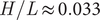 , corresponding to a peak pitch amplitude of ~
$ 0.55{}^{\circ} $
 , whereas it became unstable for
$ H/L\approx 0.063 $
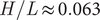 , for which the corresponding overset simulation produced a peak pitch amplitude of ~
$ 1.38{}^{\circ} $
 . The critical condition for the loss of mesh-morphing stability can therefore be expected to lie within

Accordingly, mesh morphing can be considered suitable for wave conditions close to or below the lower bound identified in the present study, whereas the overset approach should be preferred for conditions approaching or exceeding the upper bound. For operational conditions, a preliminary assessment of mesh quality and body motion is recommended. The identified range is specific to the present platform geometry, mesh resolution and mesh-motion settings, and should therefore not be interpreted as a general applicability criterion.
Beyond selecting the appropriate meshing strategy in advance, it is also useful to assess how the two approaches compare once both are applied. The comparison between mesh morphing and overset mesh under the same wave conditions showed good agreement in terms of structural displacements and mooring tensions. This improved numerical robustness, however, comes at a higher computational cost, with the overset simulations requiring ~3.6 times longer than the mesh morphing simulations under comparable numerical conditions (~18 h against 5 h per test). Since mesh morphing cannot complete the extreme sea state simulation at any mesh resolution, the two approaches should not be regarded as interchangeable options offering a trade-off between accuracy and cost for the same conditions, but rather as complementary tools covering different ranges of platform motion: mesh morphing for the operational sea states, where it is considerably cheaper, and overset for the extreme sea state, where it is the only approach able to produce a result.
The results also provide useful indications on the platform dynamic behaviour. Under the analysed regular, unidirectional waves, the response is mainly governed by surge, heave and pitch, while sway, roll and yaw are negligible. The sensitivity analysis showed that the centre of mass position has a relevant influence on the global response, and that this influence changes with the severity of the sea state. In the operational sea state, lowering the centre of mass, moving it closer to the bottom of the spar-buoy platform, improved translational stability, at the expense of a modest increase in pitch response, for which the original CoM configuration remained more favourable. The upward-shifted CoM configuration did not provide significant improvements in this case. In the extreme sea state, however, this behaviour changes: the lowered centre of mass improved both translational and rotational stability with respect to the benchmark configuration, while the upward-shifted configuration increasingly degraded both. Mooring line tensions were comparatively insensitive to the centre of mass position in both sea states, with only almost negligible differences in magnitude. These results suggest that a lower centre of mass consistently improves translational stability and becomes increasingly beneficial for rotational stability as wave severity increases. A higher centre of mass, in contrast, consistently degrades the response in both operational and extreme conditions.
Conclusion
The results obtained in this work highlight the effectiveness of CFD simulations for the analysis of Floating Offshore Wind Turbines (FOWTs). OpenFOAM provided a flexible numerical framework for reproducing the dynamic behaviour of the spar-buoy platform under regular wave conditions, with the numerical model validated against the experimental campaign of Russo et al. (Reference Russo, Contestabile, Bardazzi, Leone, Iglesias, Tomasicchio and Vicinanza2021). The adopted CFD approach allowed the main displacement components of the floating structure and the loads transmitted to the mooring system to be evaluated, providing useful information for the preliminary assessment of platform stability and design performance. The coupling with a lumped-mass-based mooring model proved particularly useful for investigating mooring line tensions while accounting for their dynamic interaction with the floating platform. Two meshing strategies were employed to cover the full range of sea states considered: mesh morphing, computationally efficient but limited to operational conditions, and overset mesh, required for the extreme sea state, where mesh morphing cannot produce a result regardless of resolution. A dimensionless criterion relating wave input to the resulting pitch amplitude was proposed to anticipate, before running the full simulation, which of the two approaches is appropriate for a given sea state. For an OC3-Hywind spar-buoy platform equipped with the NREL 5 MW wind turbine, the numerical analysis showed that a lower centre of mass improves translational stability and, under extreme wave loading, also improves rotational stability compared with the benchmark configuration. Mooring line tensions, in contrast, remained comparatively insensitive to the CoM position under the investigated conditions. These results indicate that, for the range of conditions investigated, lowering the centre of mass is broadly beneficial, although the corresponding variation in rotational response under moderate sea states should still be considered when selecting design parameters according to the target performance objective, including stability, fatigue or power efficiency.
Overall, CFD-based analyses combined with a lumped-mass mooring model represent a valuable tool for supporting the preliminary design of FOWTs and identifying promising configurations before more detailed structural analyses.
Future developments should investigate additional structural and mooring configurations, including the influence of mooring line attachment points, different wave-propagation directions, irregular sea states, combined wind and current loading and the coupled aero-servo-elastic behaviour of the complete floating wind turbine system.
Open peer review
To view the open peer review materials for this article, please visit http://doi.org/10.1017/wat.2026.10034.
Acknowledgements
Awards granted by ISCRA @ LEONARDO: We acknowledge ISCRA for awarding this project access to the LEONARDO supercomputer, owned by the EuroHPC Joint Undertaking hosted by CINECA (Italy). The authors gratefully acknowledge A. Lauria for his valuable technical assistance with the numerical modelling activities, and G. Barajas and J. L. Lara for their tutoring during the development of this work. Further, the authors used ChatGPT (OpenAI) for minor English language editing.
Author contributions
Conceptualization: A.I.; Data curation: A.I.; Data visualisation: A.I.; Methodology: A.I.; Supervision: G.S., A.S.; Writing – original draft: A.I.; Writing – review and editing: G.S., A.S. All authors approved the final submitted version of the manuscript.
Competing interests
The authors declare none.
Data availability statement
The data, code and other materials required to understand, verify and replicate the findings of this study are available upon request.
Ethics and approval
The research meets all ethical guidelines, including adherence to the legal requirements of the study country.
Funding statement
No financial support has been provided for this publication.




 Open access


Comments
No accompanying comment.