1 Introduction
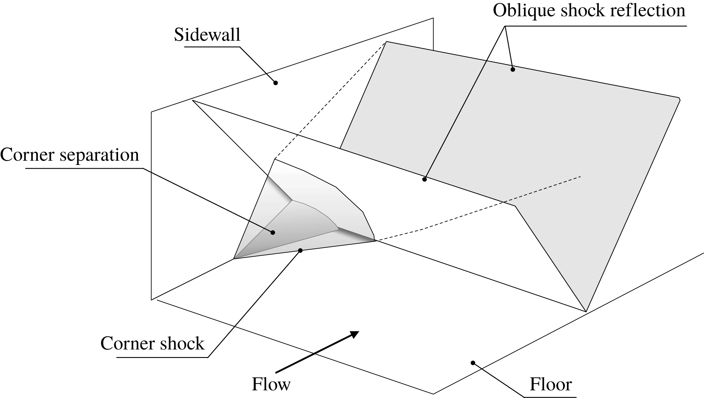
The interaction of a shock wave with a boundary layer (shock wave/turbulent boundary layer interaction (SBLI)) is one of the fundamental problems of high-speed flows in air. SBLIs have been studied for many decades, often by investigating simplified ‘canonical’ problems which form the building blocks of more complex flows. Of these, the transonic interaction of a normal shock wave with a turbulent boundary layer and the supersonic oblique shock wave reflection are probably the most important problems. Both of these flows are nominally two-dimensional, and past research has generally concentrated on the flow behaviour well away from sidewalls or edge effects (refer to the reviews of classic two-dimensional SBLI of Adamson & Messiter (Reference Adamson and Messiter1980), Délery & Dussauge (Reference Délery and Dussauge2009) and Babinsky & Harvey (Reference Babinsky and Harvey2011)). However, more recently it has been found that when such flows are studied in rectangular channels, which is the most common geometry for such investigations, any flow separation occurring in the streamwise corners formed by the junction of the floor with the sidewall can significantly change the flow field. In the transonic normal SBLI, it has been suggested by Burton & Babinsky (Reference Burton and Babinsky2012) that this is due to so-called ‘corner shocks’ altering the adverse pressure gradient (APG) experienced by the flow elsewhere. These corner shocks arise from the displacement effect of the corner separation, which generally occurs well upstream of any separation around the central regions of the channel walls, because corner boundary layers typically feature considerable regions of low momentum as a result of the viscous interactions with two surfaces. For the case of a supersonic oblique shock wave reflection interacting with the boundary layer on the floor of a channel (as sketched in figure 1), a similar mechanism has been suggested by Babinsky, Oorebeek & Cottingham (Reference Babinsky, Oorebeek and Cottingham2013), but a comprehensive understanding of the role of ‘corner shocks’ has not yet been reached.
Schematic diagram of corner separation shock wave in an oblique SBLI (adapted from Babinsky et al. (Reference Babinsky, Oorebeek and Cottingham2013)).

The purpose of this study is to extend the current state of knowledge on the three-dimensional flow structures induced by sidewall effects and their effect on the flow elsewhere for an oblique SBLI. The aim is to determine how the relative magnitude of corner separation modifies the size and shape of ‘quasi-two-dimensional’ separation observed in the centre of a duct and by what physical mechanisms this is achieved. To achieve these goals, experiments have been conducted where the corner separations for an established reflecting shock interaction are manipulated to produce corner effects varying in relative size from moderate to significant. The baseline flow conditions are chosen to result in substantial separations both in the corners and along the centreline, which is thought to be a good starting point for this study.
2 Methodology
2.1 Wind tunnel set-up
Experiments have been performed in the supersonic wind tunnel no. 1 in the Cambridge University Aerodynamics Laboratory. This tunnel is of the intermittent blow-down type driven by a high-pressure reservoir of dry air. A nominal free-stream Mach number of 2.5 is used for all experiments with a unit Reynolds number of
 $40\times 10^{6}~\text{m}^{-1}$
. The stagnation pressure is set to 380 kPa (fluctuating by approximately 0.5 % during a typical run) and the stagnation temperature is set at
 $296~\text{K}\pm 3~\text{K}$
. During tunnel runs the stagnation temperature in the settling chamber is observed to increase at a rate of
 $0.1~\text{K}~\text{s}^{-1}$
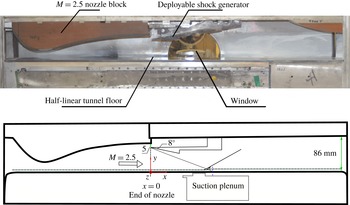
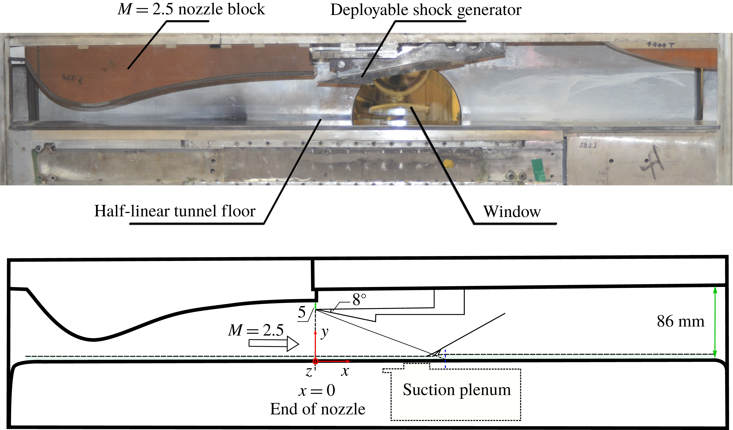
, giving a maximum variation of 6 K. The set-up for the working section and key dimensions are shown in figure 2. A ‘half-liner’ configuration with a single nozzle block is used here. By blocking the lower half of the tunnel, the streamwise distance for observation through the sidewall window is almost doubled and the possible run time is increased. The resulting working section is 114 mm wide and 86 mm tall. A deployable wedge on the ceiling of the tunnel is lowered to
 $8^{\circ }$
to generate an oblique shock once the desired supersonic flow is developed. A gap of 5 mm between the leading edge of the deployed shock generator and the upper surface of the tunnel enables the boundary layer on the nozzle block to disappear into the gap and therefore creates a ‘cleaner’ environment for the generation of the incident shock. A coordinate system following convention is used, where
 $x$
refers to the streamwise direction with
 $x=0~\text{mm}$
corresponding to the end of the nozzle. The theoretical inviscid shock reflection location is at
 $x=135~\text{mm}$
. Coordinate
 $y$
is measured vertically upwards with
 $y=0$
referring to the tunnel floor. Spanwise position is denoted by
 $z$
, measuring from the centreline of the tunnel floor with the sidewalls being at
 $z=\pm 57~\text{mm}$
.
Set-up for the working section.
2.2 Flow measurement techniques
Two flow visualisation techniques are utilised to develop an intuitive understanding of the flow field. A two-mirror
 $z$
-type horizontal schlieren system enables the observation of regions with high density gradients such as shock waves and boundary layers. Surface oil-flow visualisations provide time-averaged surface streamline patterns on the tunnel floor and sidewalls. A mixture of kerosene, finely powdered titanium dioxide, oleic acid and a small amount of lubricating oil to add viscosity is used. The resulting oil-flow patterns are photographed once the tunnel runs have finished. A live video is recorded along with the still image to help eradicate any ambiguity caused by mixture smearing upon tunnel shutdown. To allow an accurate estimation of separation sizes, images presented here are corrected for perspective distortion and processed to improve the visibility of flow patterns. The obtained oil streak images are then used to infer the existence of critical points, determine the locations of separation and reattachment, and hence construct the surface flow topology. While the oil mixture follows the surface streamlines well and represents the flow topology accurately for attached flows, it has been noted by Squire (Reference Squire1961) that an early (i.e. more upstream) indication of separation can occur as the oil tends to stop moving before the surface skin friction vanishes in an APG. More specifically, oil streaks can underestimate the distance to separation by up to 5 % of the upstream influence, making the error in indicated separation location of the order of 0.2 times the incoming boundary layer thickness (approximately 1.2 mm) for this study. Squire (Reference Squire1961) also showed that for a boundary layer developed by supersonic external flows, the effect of the oil film on the skin friction pattern is negligible. Given that the errors are relatively small, the lengths of shock-induced separated regions shown in the oil-flow visualisation can therefore still be compared among different experiments with confidence.
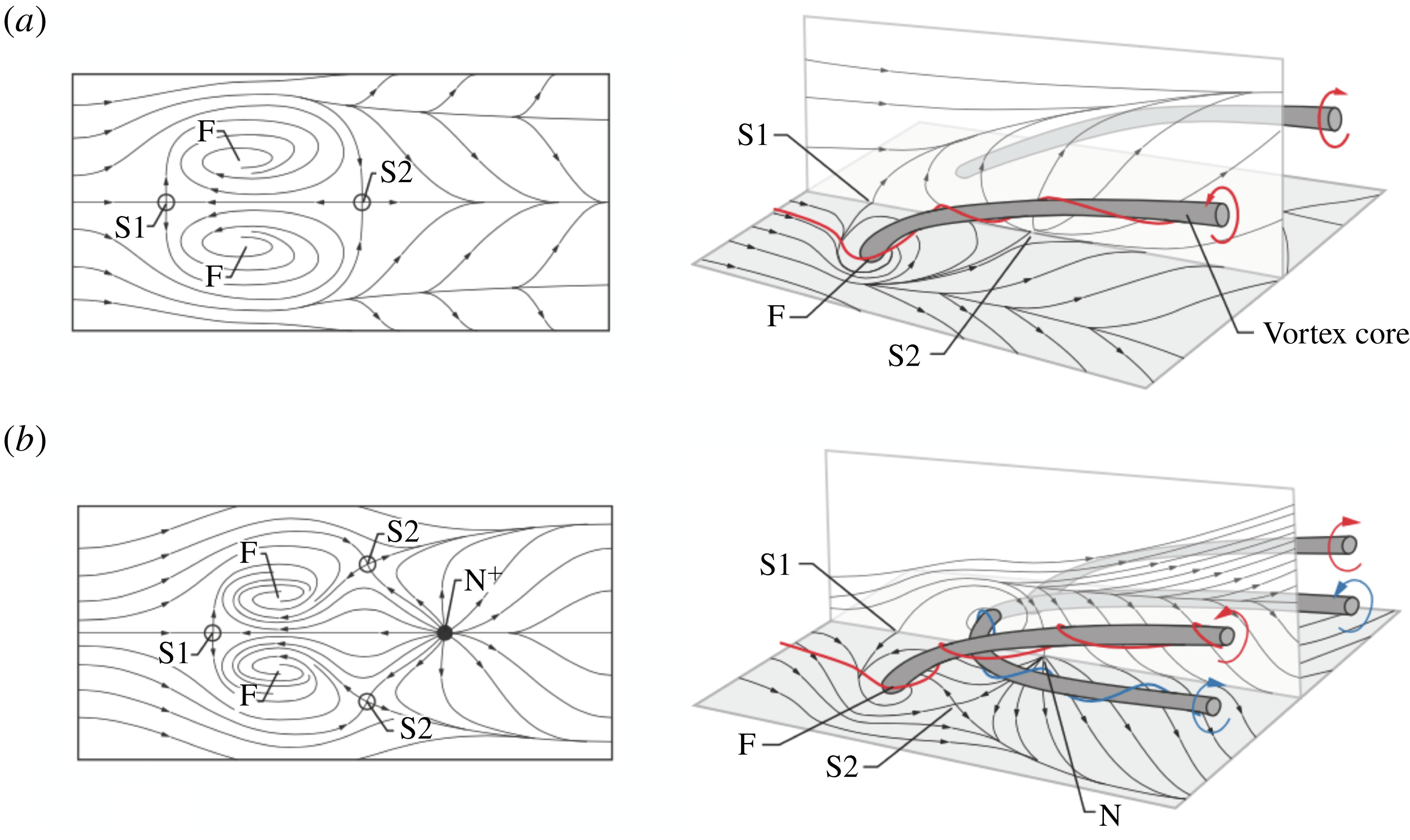
Three-dimensional flow fields associated with flow separations described by Perry & Hornung (Reference Perry and Hornung1984): (a) owl-face of the first kind; (b) owl-face of the second kind (adapted from Colliss (Reference Colliss2014)). S stands for saddle point, N refers to node, and F represents focus.

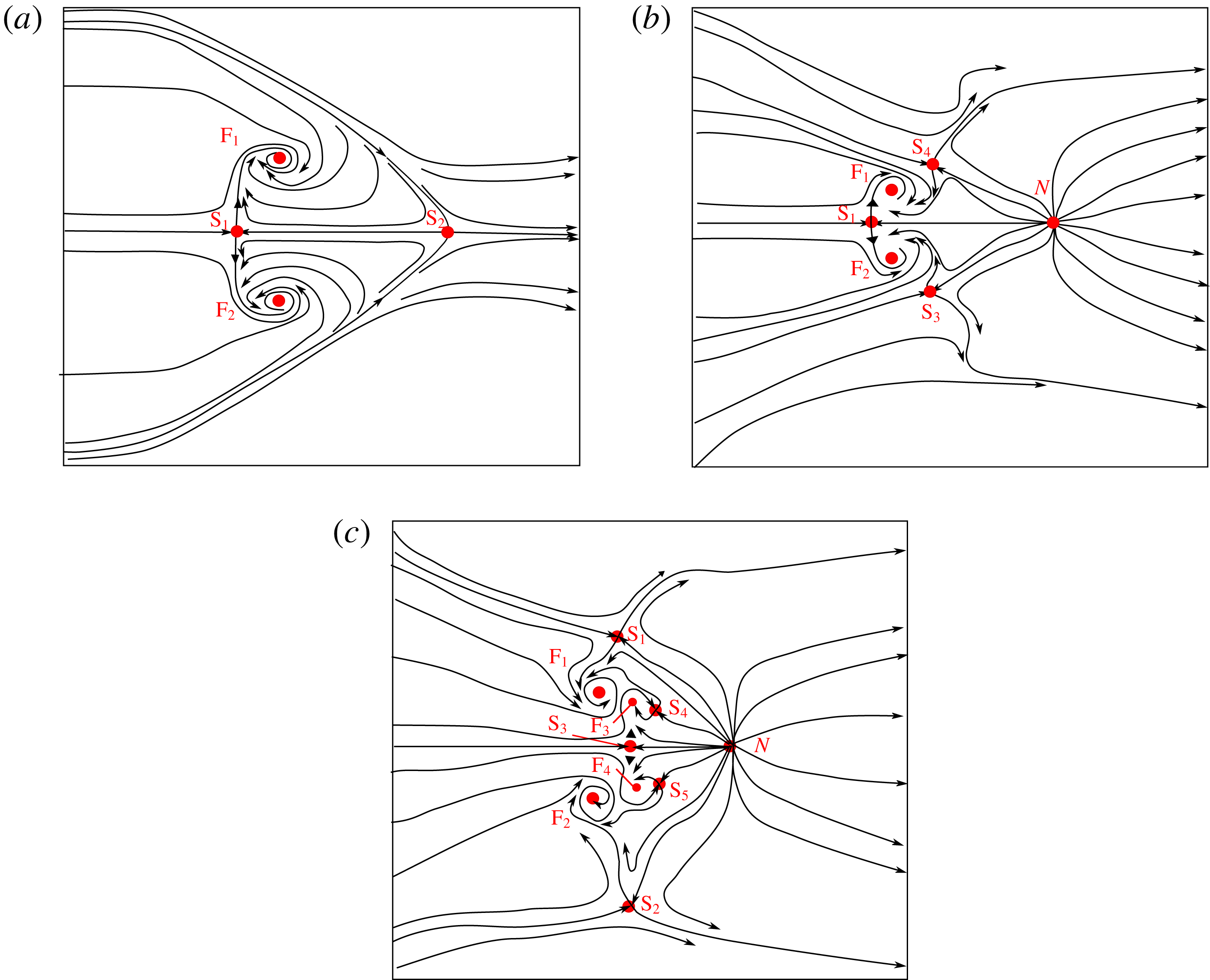
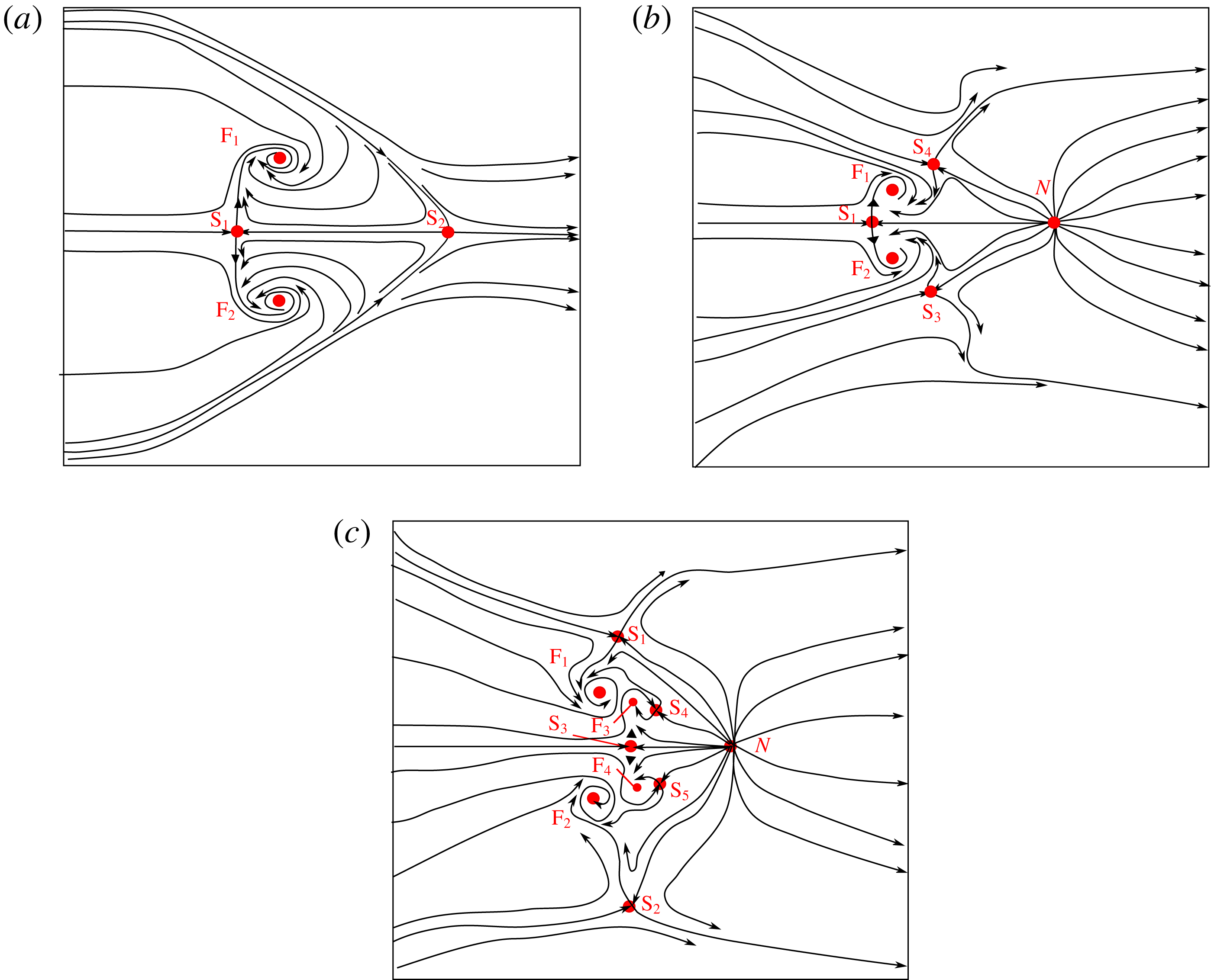
A common feature of three-dimensional separation is the ‘owl-face’ proposed by Perry & Hornung (Reference Perry and Hornung1984). Figure 3(a) shows an ‘owl-face of the first kind’, containing a leading-edge saddle point (S1) which diverges the upstream streamlines. In this flow several friction lines coming from upstream, and the separation line, spiral into the focus points (F), which are the surface traces of ‘tornado-like’ vortices. Fluid then escapes through these vortices, creating an ‘open’ separation. To ensure topological consistency, a second saddle point S2 exists on the reattachment line. Shown in figure 3(b), the ‘owl-face of the second kind’ is of a similar yet more complicated organisation. More specifically, the downstream portion differs in the way the rear saddle point is split into two and offset laterally, with an additional node (N) added to build a topologically consistent and physically possible pattern. The effect on the outer flow is to induce an additional horseshoe vortex, which partially offsets the upwash around the centre span produced by the more widely spaced primary vortices.
The average wall pressure measurements are conducted via static tappings (internal diameter 0.15 mm) embedded in the wind tunnel floor and sidewall. They are connected by neoprene tubing to a differential pressure transducer (NetScanner 9116). Accounting for the manufacturer’s quoted accuracy and calibration uncertainty, the measurements from the NetScanner system give a total error on normalised pressures from taps of
 $\pm 0.5\,\%$
. Pressure-sensitive paint (PSP) supplied by Innovative Scientific Solution Incorporated (ISSI) is introduced to provide higher-spatial-resolution data. To apply PSP, the surface of interest is sprayed with a special polymer binder seeded with luminescent molecules. When irradiated by ultraviolet (UV) light, the resultant luminescence intensity is proportional to the normalised surface pressure. A reference image with no air flow is recorded immediately before each run to minimise any effects of paint degradation. This intensity ratio of two distinct conditions can then be calibrated by the in situ pressure taps to map out the pressure distribution for the complete flow field. A comparison between pressure taps and the calibrated PSP data suggests an error bound of
 $\pm 3\,\%$
for the PSP measurement. However, it should be pointed out that this
 $\pm 3\,\%$
value excludes surface temperature variations. In regions where the thermal properties of the wall change (attachment screws, fillers), a much greater error is observed. Static wall pressure distributions along the tunnel floor centreline are obtained from the PSP images. Noise is reduced by averaging 15 spanwise pixels either side of the centreline (corresponding to a 1.5 mm span on the tunnel floor). Averaging over 10 pixels (0.4 mm) in the streamwise direction allows a further reduction in noise, without significant deterioration of spatial resolution.
Streamwise velocity is measured with a two-component laser Doppler anemometry (LDA) system. Two pairs of coherent laser beams, with wavelengths of 561 nm and 532 nm, respectively, are intersected at a specific point in the working section to produce an interference fringe pattern, measuring
 $98~\unicode[STIX]{x03BC}\text{m}$
in diameter by
 $1.4~\text{mm}$
in spanwise length. The system is aligned at
 $45^{\circ }$
to the free-stream direction, enabling the measured vectors by both channels to carry similar magnitudes of velocities and signal-to-noise ratios. The positional uncertainty of the measured volume is
 $\pm 0.2~\text{mm}$
,
 $\pm 0.02~\text{mm}$
and
 $\pm 0.01~\text{mm}$
for
 $x$
,
 $y$
and
 $z$
, respectively. The incoming flow is seeded with droplets of paraffin, formed by passing high-pressure air through an oil reservoir. An investigation by Colliss et al. (Reference Colliss, Babinsky, Nübler and Lutz2014) estimated the mean diameter of the particles as approximately
 $0.5~\unicode[STIX]{x03BC}\text{m}$
, and determined that the droplets are adequately small to follow the flow.
Continuous streamwise traverses are used to examine the velocity variation along the centreline, with the measurement volume moving through the oblique shock interaction at a rate of
 $4~\text{mm}~\text{s}^{-1}$
. The seeding density is high in the outer inviscid flow, ensuring that at least 5000 samples are collected to calculate the time-averaged velocities. Taking alignment errors and the manufacturer’s quoted uncertainty into consideration, the free-stream velocities shown here are determined to an accuracy better than 1.5 %. Boundary layer traverses are conducted at
 $x=80~\text{mm}$
to characterise the inflow properties, and also further downstream from the interaction at
 $x=160~\text{mm}$
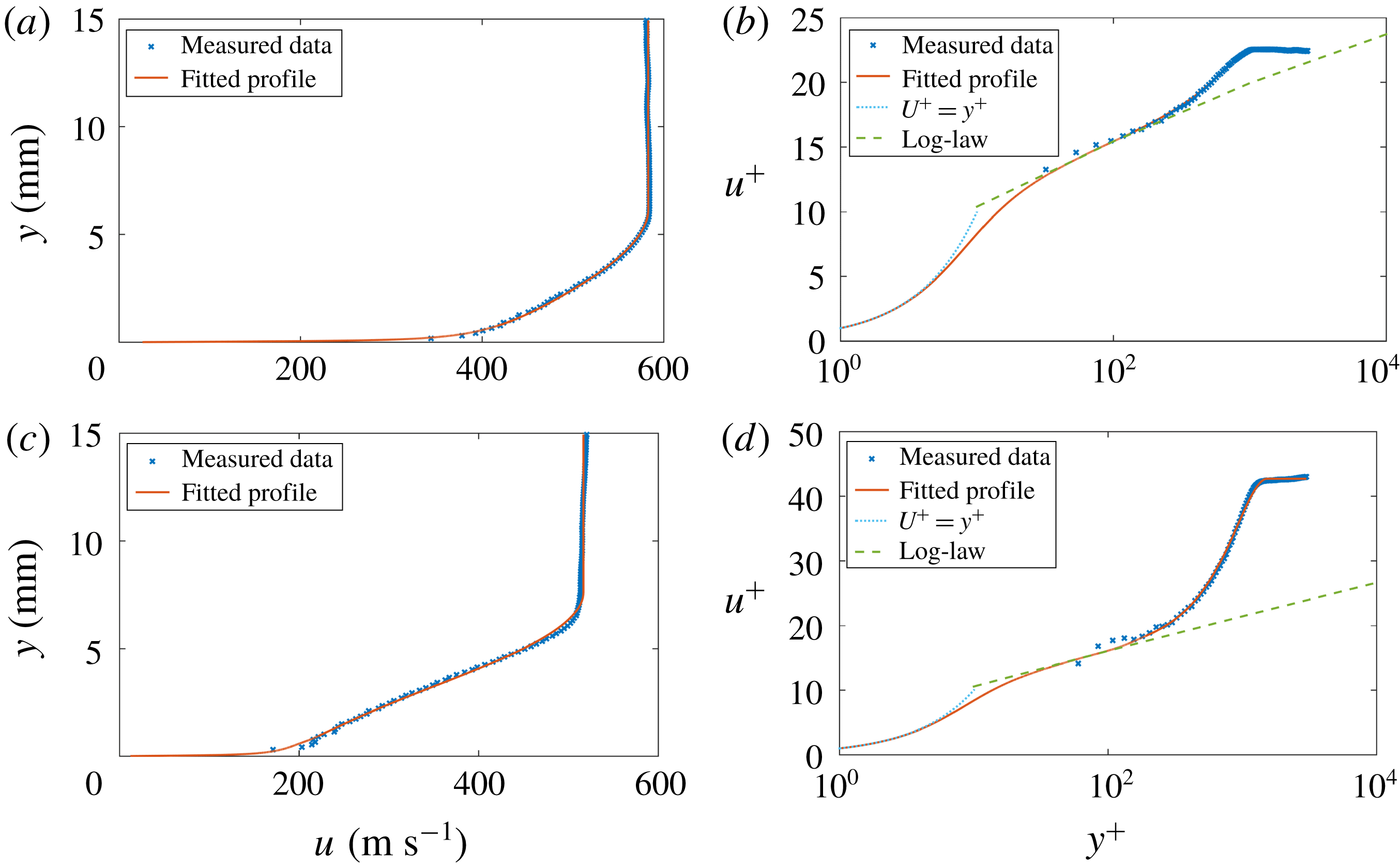
. Owing to the low seeding levels near the wall and optical reflection, data measured within 0.18 mm of the tunnel floor are rejected. Integrating directly from the raw data can lead to overestimation of integrated boundary layer properties. A fitting scheme is therefore applied to the measured points to more faithfully represent the boundary layer profiles. More specifically, a wall-wake velocity profile suggested by Sun & Childs (Reference Sun and Childs1973), transformed by the equation of van Driest (Reference van Driest1951) to account for compressibility effects, is adopted to fit the measured data in the logarithmic and wake regions. The fitted scheme is further extrapolated towards the wall with the method of Musker (Reference Musker1979). The model provides an excellent fit to the turbulent boundary layer data, with the thickness and incompressible integral parameters calculated with an accuracy within 5 % of the true value (Titchener, Colliss & Babinsky Reference Titchener, Colliss and Babinsky2015).
2.3 Corner flow manipulation
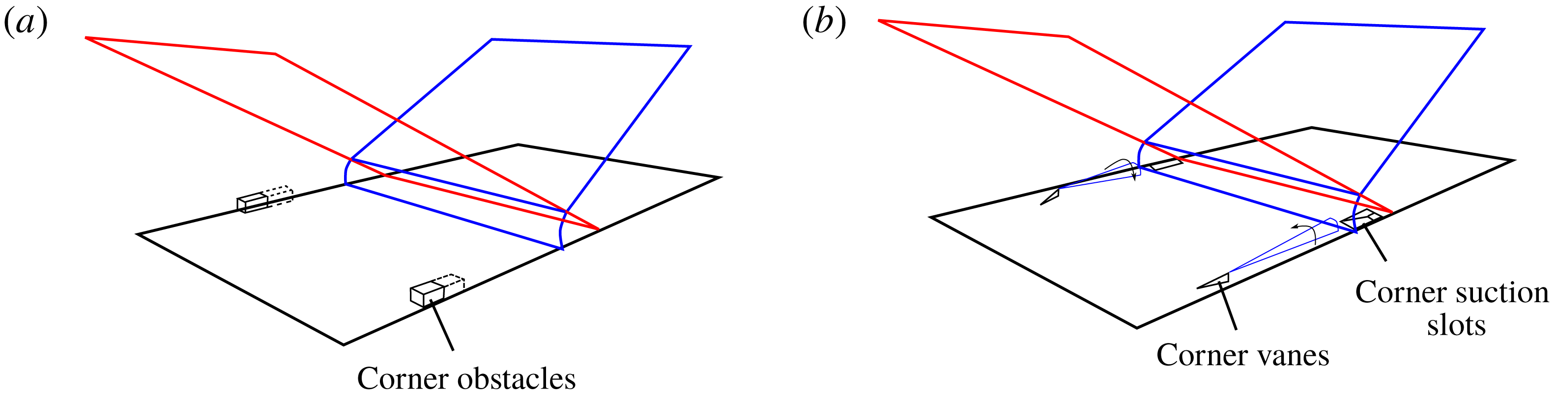
Experimental arrangements: (a) corner obstacles; (b) corner control techniques.
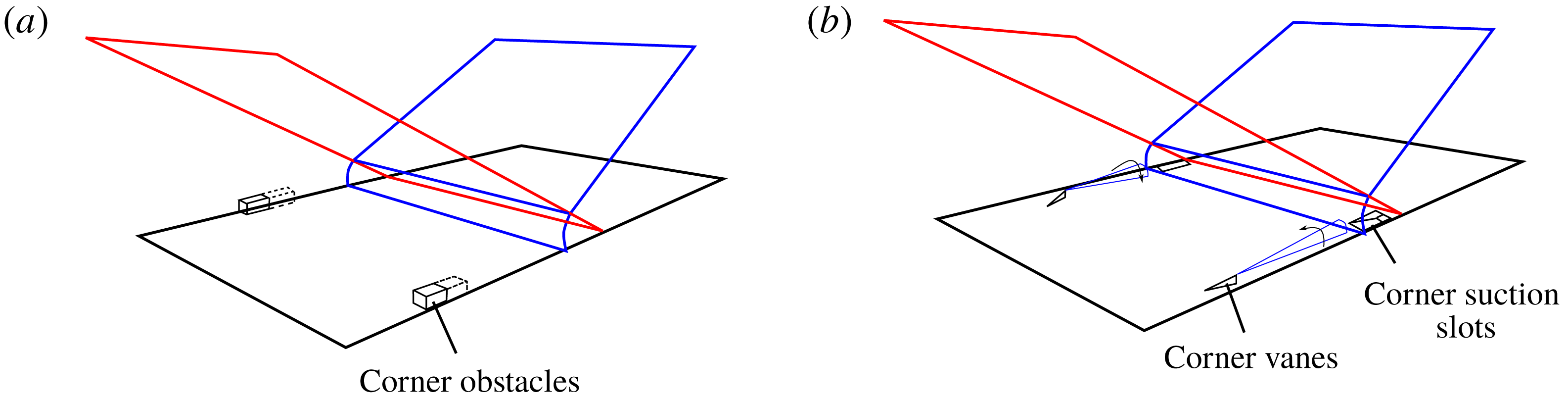
To examine how changes in the corner flow field can affect the main oblique SBLI, modifications to the corner geometry are applied to change the onset and magnitude of corner separations. Two obstacles, as depicted in figure 4(a), are utilised to increase the size of corner separations. These obstructions, consisting of blocks with dimensions
 $10~\text{mm}\times 10~\text{mm}\times 20~\text{mm}$
, are placed ahead of the inviscid shock location. The streamwise positions of the block front edge range from
 $x_{block}=75~\text{mm}$
to
 $x_{block}=130~\text{mm}$
, with a minimum distance of 5 mm between two consecutive locations. A pair of elongated blocks with a length of 40 mm is also tested at
 $x_{block}=85~\text{mm}$
. Corner suction and vane-type micro-vortex generators (micro-VGs), as shown in figure 4(b), are introduced to study the effect of a reduced corner separation. The vane height is 3 mm (approximately 50 % of the incoming boundary layer thickness) and the vanes are set at an angle of
 $15^{\circ }$
to the inflow. The trailing edge of the micro-VGs is placed at
 $x_{vg}=50~\text{mm}$
, making the non-dimensional distance between the inviscid shock reflection location and the VG trailing edge roughly 28 device heights. Corner suction is placed in the interaction zone, with the leading edge of the bleed slots located at
 $x_{slot}=100~\text{mm}$
. The slot is 32 mm long by 5 mm wide, with the angle set to be
 $20^{\circ }$
. The suction mass flow rate is 0.28 % of the mass flow through the wind tunnel working section. This achievable amount of bleed is limited due to the low local surface pressure associated with the high Mach number. The aim of all these corner flow manipulations is to compare flow fields with an incident shock of identical strength and location, but different corner separation geometry.
3 Results and discussion
Flow structure of undisturbed baseline interaction presented by (a) schlieren photograph and (b) streamwise velocity at
 $y=15~\text{mm}$
,
 $z=0~\text{mm}$
.

Boundary layer profiles measured with LDA along the tunnel floor centreline for baseline case: (a) inflow boundary layer profile at
 $x=80~\text{mm}$
; (b) inflow boundary layer profile in law-of-the-wall coordinates; (c) downstream boundary layer profile at
 $x=160~\text{mm}$
; and (d) downstream boundary layer profile in law-of-the-wall coordinates.
3.1 Baseline flow
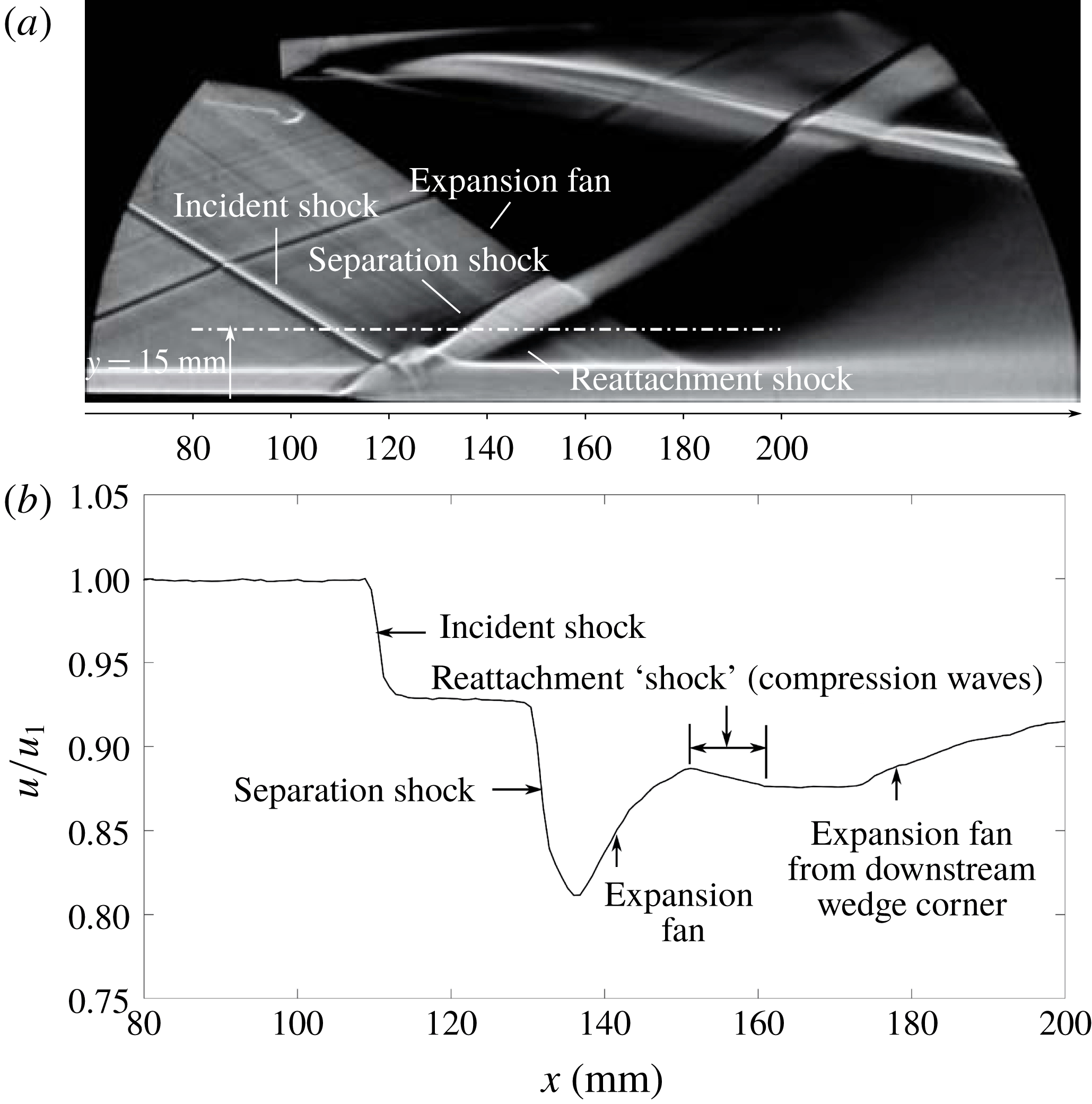
Figure 5(a) shows a schlieren image of the unmodified baseline interaction, which is seen to be globally stable in the high-speed video recording. The standard pattern of a separation and reattachment shock bounding an expansion fan suggests the presence of a separated region. The oblique interaction domain spreads from
 $x=110~\text{mm}$
to
 $x=140~\text{mm}$
with the inviscid shock reflection located at
 $x=135~\text{mm}$
. At the top of the image, a strong expansion fan emanates from the downstream wedge corner, impinging on the tunnel floor at approximately
 $x=200~\text{mm}$
, roughly
 $10\unicode[STIX]{x1D6FF}$
behind the inviscid shock reflection location. The streamwise velocity variation measured along
 $y=15~\text{mm}$
on the central symmetry plane (marked by a white dot-dashed line in figure 5
a) is shown in figure 5(b). The flow is initially at the incoming free-stream velocity (
 $u_{1}$
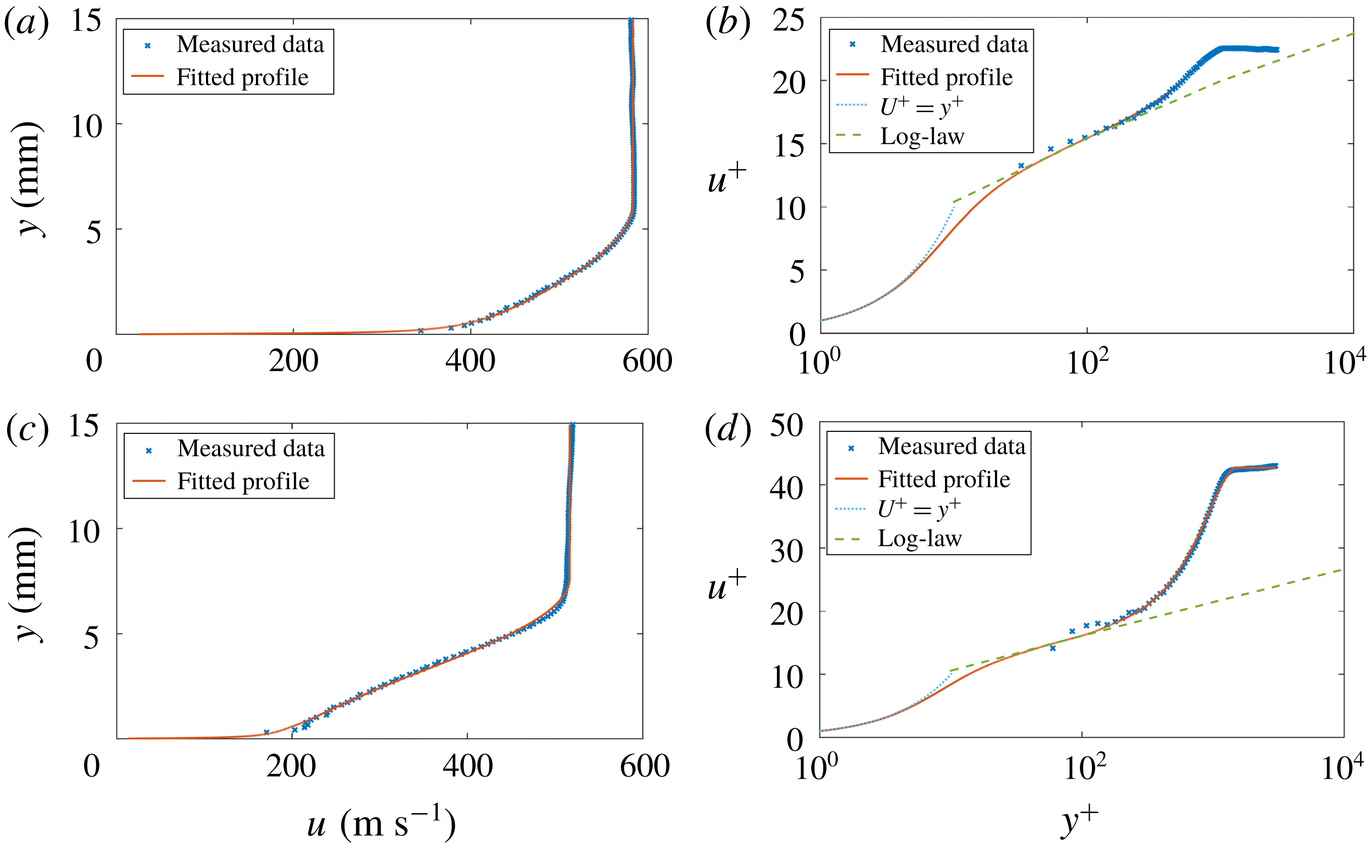
), and then decelerates through the incident shock. The following two deceleration steps bounding a re-acceleration region correspond to the typical separated interaction wave pattern depicted in the schlieren photograph. The LDA measurements indicate that the reattachment shock is weak and quite smeared out, even in the outer inviscid flow. The boundary layer profiles measured at two streamwise positions along the centreline are presented in figure 6. Here the inflow boundary layer obtained at
 $x=80~\text{mm}$
, shown in figure 6(a,b), is 6.1 mm thick, and the incompressible integral values are: displacement thickness
 $\unicode[STIX]{x1D6FF}^{\ast }=0.84~\text{mm}$
, momentum thickness
 $\unicode[STIX]{x1D703}=0.61~\text{mm}$
and shape factor
 $H_{i}=1.37$
. There is a well-defined log region and the agreement with the analytical profile is excellent throughout. A rapid thickening of the boundary layer can be observed across the interaction. The boundary layer measured at
 $x=160~\text{mm}$
(figure 6
c,d), around
 $4\unicode[STIX]{x1D6FF}$
downstream of the inviscid shock reflection, is 7.6 mm thick, with a displacement thickness of 2.14 mm, momentum thickness of 1.17 mm and a shape factor of 1.83.
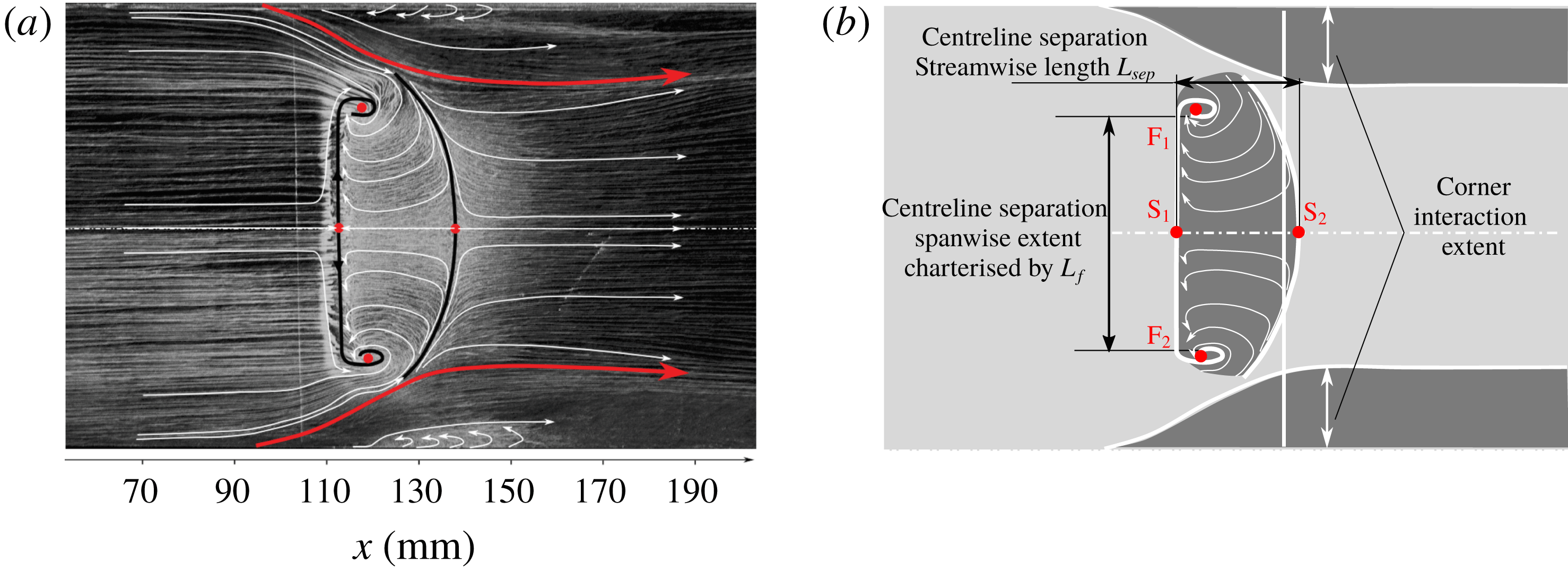
Interpretation of flow topology on the tunnel floor for baseline flow by (a) surface oil-flow visualisation; (b) schematic illustration of separation sizes extracted from the oil flow. Limiting streamlines and the footprint of the separation are suggested for clarity; the vertical line indicates the inviscid shock location.
Surface pressure distribution through baseline interaction on the tunnel floor: (a) PSP map; (b) static wall pressure distribution along the tunnel floor centreline.
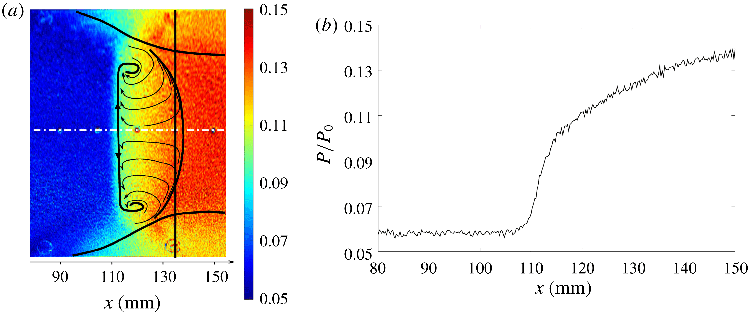
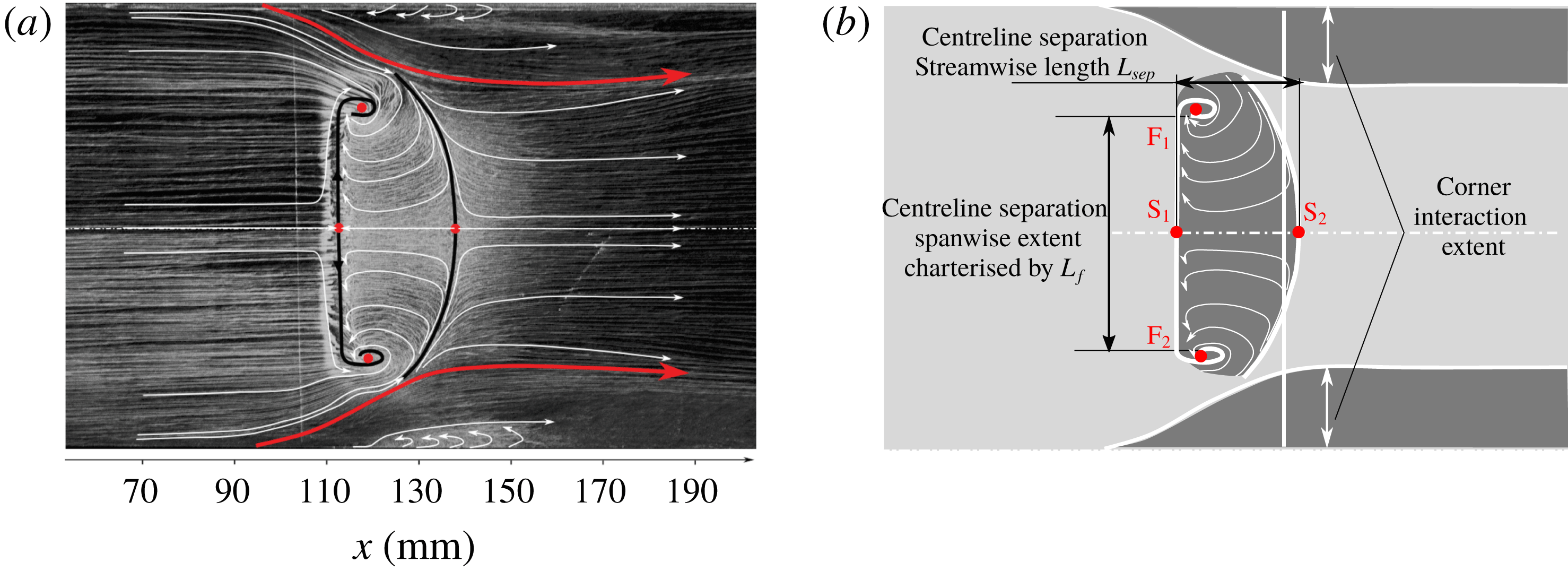
Figure 7(a) shows the oil-flow visualisation on the tunnel floor. The corner separation regions are indicated with a red line, while the black lines mark the centreline separation and reattachment locations. Limiting streamlines are also shown for clarity, with the surface flow topology presented and annotated schematically in figure 7(b). Here the inviscid shock location, from an extrapolation of the incident shock seen in figure 5(a), is marked by a vertical line. The skin friction lines suggest that the centreline separation topology falls into the ‘owl-face of the first kind’ category, with two saddle points (S) and a pair of foci (F) clearly identifiable. The sizeable separation region in the centre of the tunnel floor exhibits a relatively two-dimensional pattern for much of its spanwise extent. However, towards the sidewalls the streamwise separation length reduces and the separated region is bounded by distinct foci on either side. On the centreline the separation starts at
 $x=112~\text{mm}$
, measuring 25 mm in streamwise direction (termed
 $L_{sep}$
). The spanwise separation width
 $L_{f}$
is defined as the distance between the two foci and covers 62 mm (54 % of working section width). In each corner region, the presence of reversed flow is suggested by the displacement of the incoming streamlines, originating approximately 18 mm ahead of the centreline separation. The corner interaction ‘footprints’ are seen to extend to approximately 22 mm from the sidewall (20 % of full span). Although critical points are not clearly seen in the corners, the recirculating streamlines suggest the presence of a focus and the formation of a corner vortex on both sides. A narrow attached flow channel is observed between the central and corner separations.
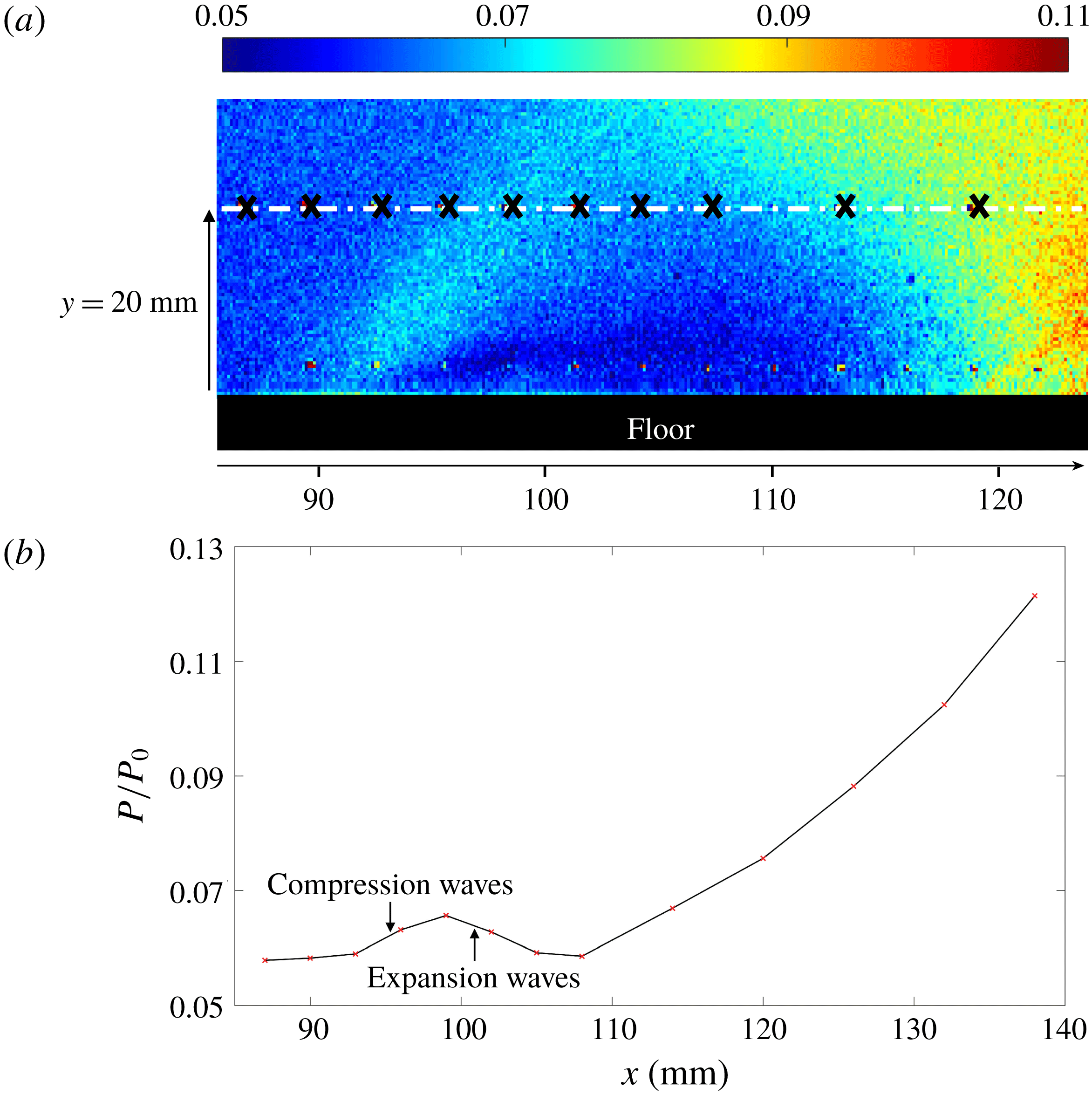
Structure of the wave pattern induced by the corner separation illustrated by: (a) PSP map on the right sidewall; (b) static wall pressure distribution measured by pressure tappings at
 $z=57~\text{mm},y=20~\text{mm}$
.
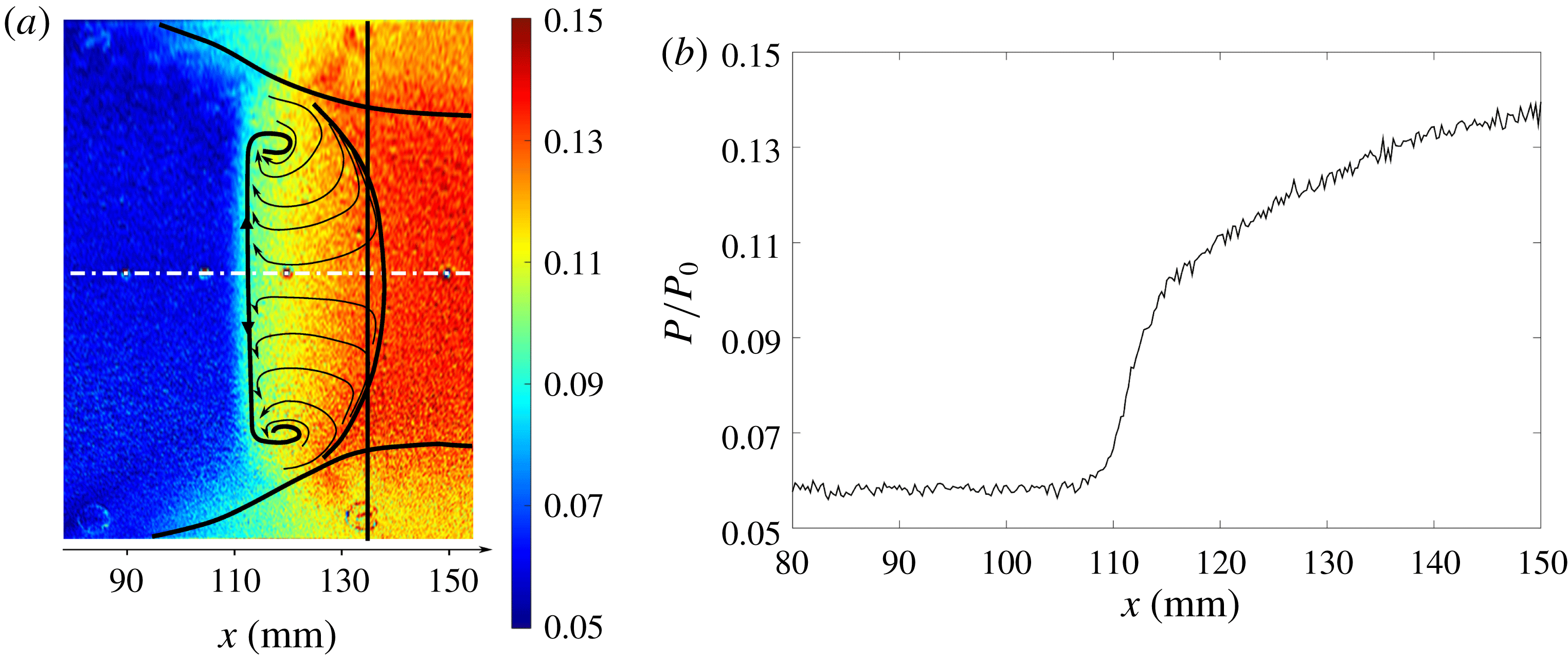
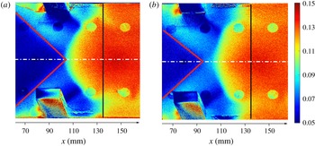
The static pressure on the tunnel floor is presented in figure 8, as a PSP map (figure 8 a) and the distribution along the centreline (figure 8 b). The simplified separation topology is superimposed on the PSP map (figure 8 a) to allow a comparison with the oil-flow visualisation. It can be seen that there is a uniform region of low pressure upstream of the oblique interaction. This is followed by a rapid pressure rise starting near the separation onset. This separation shock footprint presents little spanwise variation, except for the additional pressure smearing as the sidewalls are approached. Comparing the pressure distribution with the separation boundaries, it can be seen that the more upstream pressure rise near the sidewalls corresponds well to the onset of corner separation. This smeared-out corner pressure distribution is therefore likely to be linked to the corner separation.
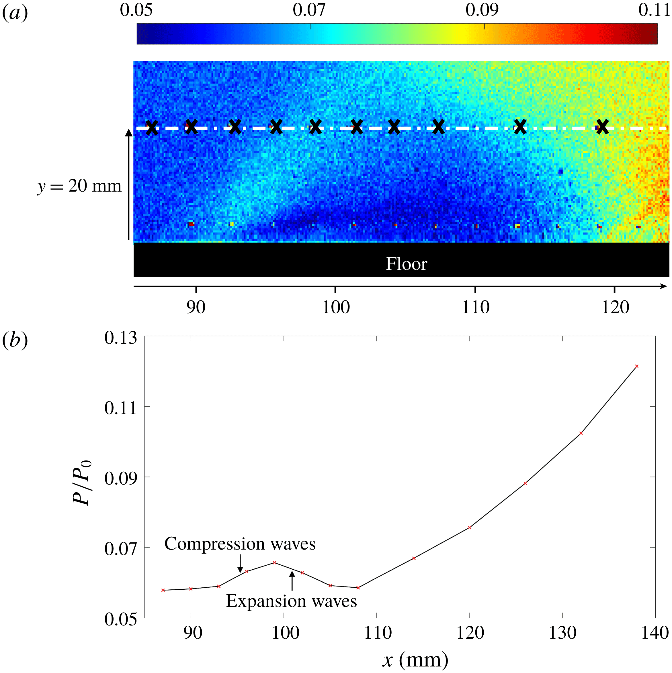
The PSP map shown in figure 9(a) presents the pressure distribution on the right sidewall. Here, no quantitative data can be extracted due to a combination of more prominent image noise (poor UV light access) and thermal effects. As identified from the oil-flow image, the corner separation on the sidewall extends approximately 18 mm away from the tunnel floor, with the separation onset located at
 $x=87~\text{mm}$
. The wall pressure measured with taps located in 3 mm intervals along the white dashed line at
 $y=20~\text{mm}$
is shown in figure 9(b). It is observed that the pressure near the onset of corner separation first increases and then reduces again. This suggests that the wave pattern, caused by the corner separation, consists of a compression fan followed by expansion waves of equal strength. The presence and strength of the expansion waves have been overlooked in previous studies (Burton & Babinsky Reference Burton and Babinsky2012; Eagle & Driscoll Reference Eagle and Driscoll2014).
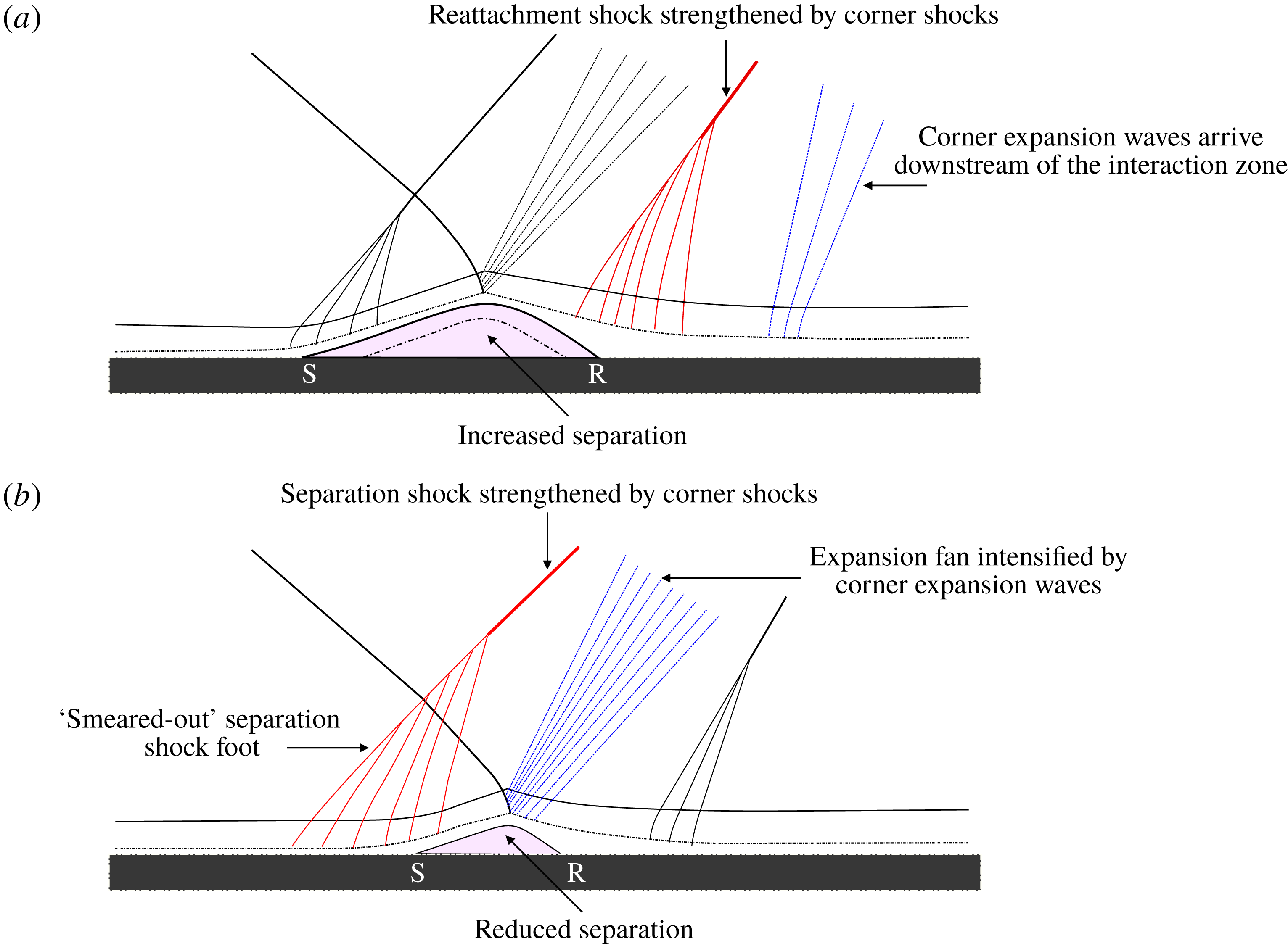
Schematic illustration of corner effects on baseline flow: (a) diagram of corner wave structure; (b) diagram of SBLI structure on the central symmetry plane.
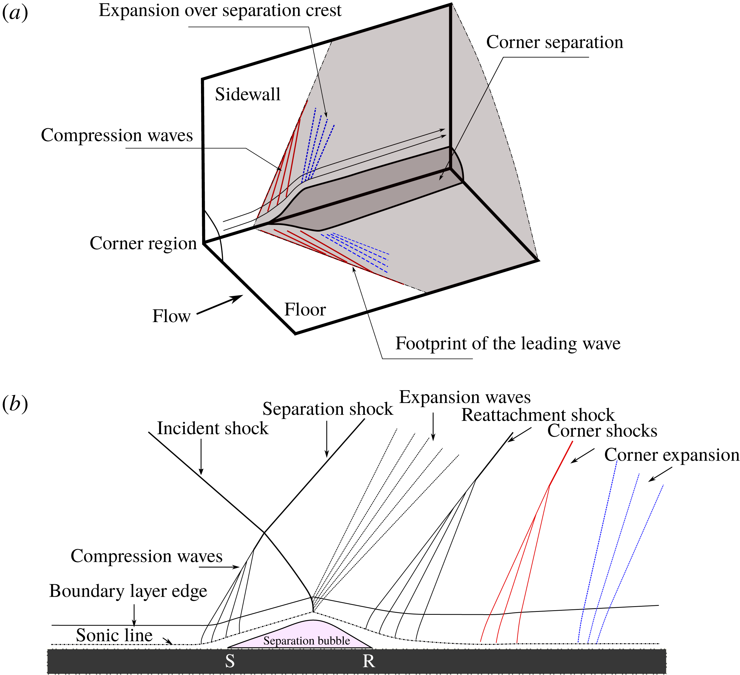
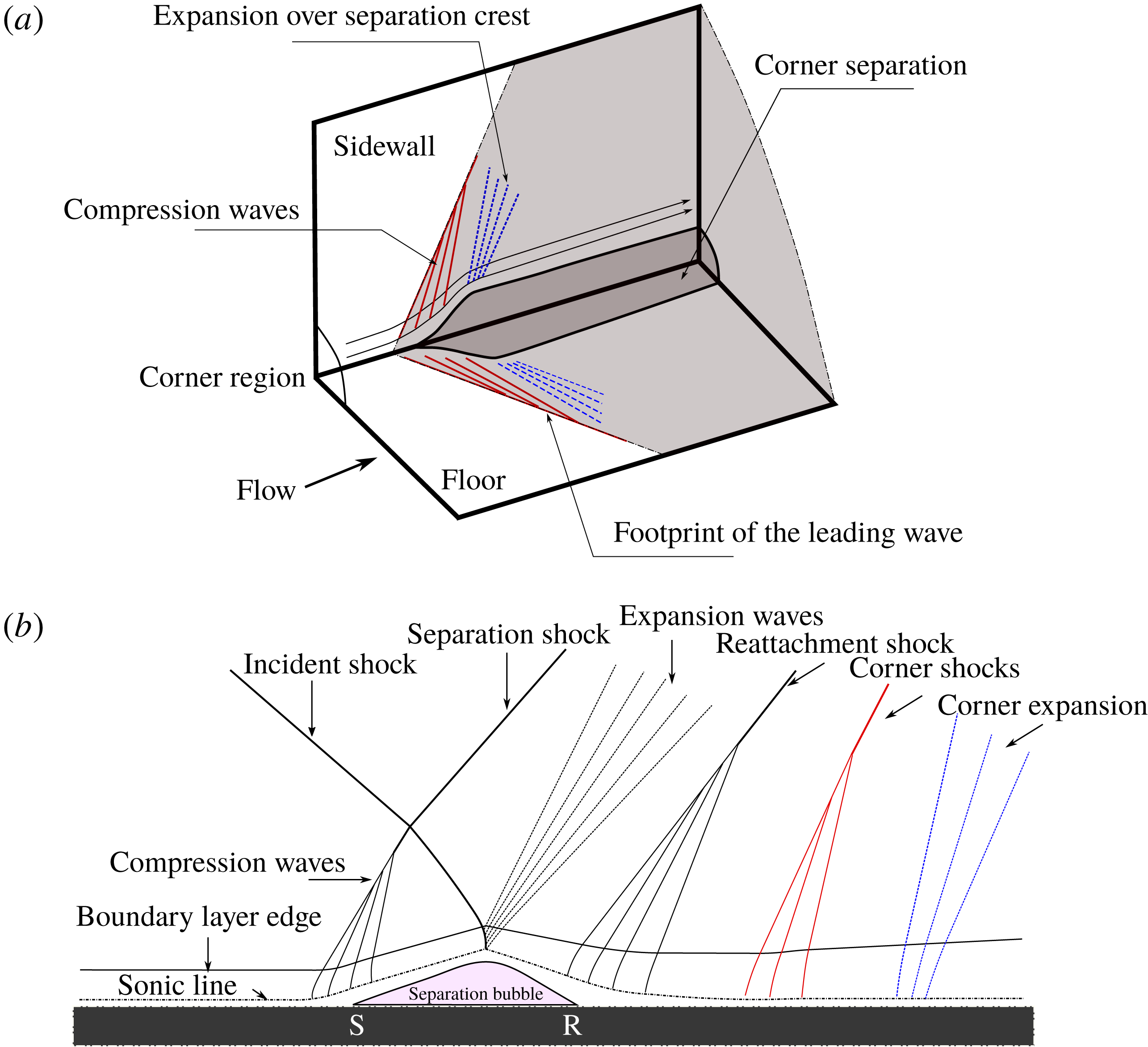
Figure 10(a) schematically illustrates the waves induced by corner separation. It is proposed that the separation acts like an aerodynamic ‘bump’, which first deflects the supersonic flow away from the corner, generating compression waves, and then returns the flow towards the streamwise direction, which is the cause of the observed expansion waves. An adverse and then favourable pressure gradient is therefore produced, which can alter the pressure distribution elsewhere in the flow field as the corner waves propagate downstream. For further analysis of the oblique SBLI flow field, it is important to trace the pattern of these waves generated by corner separation, as this helps to determine which and how other flow regions are influenced by corner effects. Of particular interest is the location of the most upstream leading compression wave along the floor. The PSP image on the tunnel floor (figure 8 a) shows this wave very clearly in the region ahead of the SBLI. Once the wave enters the interaction zone, its footprint is, however, no longer easily identifiable. It is expected that the corner waves will change direction as they penetrate into non-uniform regions and interact with other waves. However, these changes of direction are relatively small. Therefore, a rough approach to determine the upstream boundary of the corner influence region is to define a ‘corner shock footprint’ which combines the leading compression into a single line. The location and direction of this line are determined from the PSP map on the floor and, for simplicity, the footprint is assumed to follow a straight line across the interaction domain (until the central span is reached where it will cross with the equivalent wave from the opposite corner). When this footprint is applied to the oil-flow image, as shown in figure 12, it is observed that the lines generally pass through the point where inflow skin friction lines near the sides of the tunnel are initially deflected towards the centre by the displacement effect of corner separation.
The modification of the pressure gradient by the corner waves appears to be the primary mechanism behind the link between the corner separation size and the other areas of separation. As shown in figure 9(b), the pressure downstream of the expansion fan is approximately the same as that of the inflow, indicating that the pressure rise induced by the corner shock is offset by the following expansion waves. For the region close to the corner separation, a milder APG is hence produced due to a combination of an earlier onset of pressure rise caused by corner shock and an unchanged total shock-induced pressure rise as in the two-dimensional oblique SBLI because of the cancellation effect of the subsequent expansion. This reduced APG, as evidenced by the tunnel floor pressure distribution (figure 8 a), is the most likely cause of the attached channel observed between the corner and central separations.
Figure 10(b) shows schematically the influence of the corner wave pattern on the flow in the central symmetry plane. Here the corner shocks and the following expansion waves arrive well behind the oblique interaction, with the streamwise intersection point of the corner shocks estimated to be at
 $x=160~\text{mm}$
. The SBLI is therefore not influenced by corner effects, which explains the localised quasi-two-dimensional separation topology seen in figure 7.
The results suggest that for an oblique SBLI the influence of corner effects depends on the relative position of corner waves with respect to the main interaction. For the actual region of corner flow, where the floor and sidewall boundary layers meet, separation is generally observed to occur earlier than elsewhere. In the central region, the corner waves are too far downstream to influence the interaction. In the region between the corner separations and the centre, the oncoming flow along the floor first meets the corner waves before encountering the main interaction. This has the effect to smear out the pressure rise through the SBLI, leading to a reduction or even absence of separation.
To test the above arguments, experiments are performed, where the size of corner separations is deliberately altered, thus changing the positions of corner waves relative to the impinging shock.
3.2 Interaction with reduced corner separations
Schlieren photograph with micro-VGs (
 $x_{vg}=50~\text{mm}$
) and corner suction (
 $x_{slot}=100~\text{mm}$
) employed in tandem to reduce corner effects.
Surface flow visualisation on the tunnel floor for the experiment with combined control applied: (a) oil-flow image; (b) PSP map.
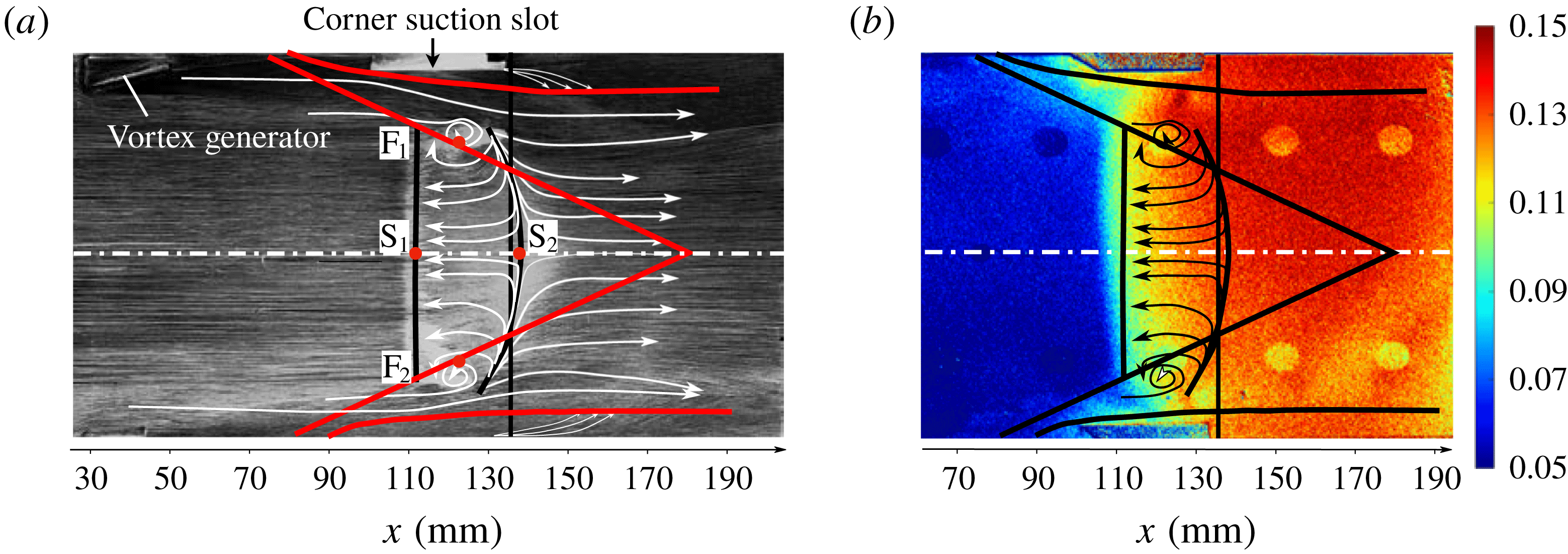
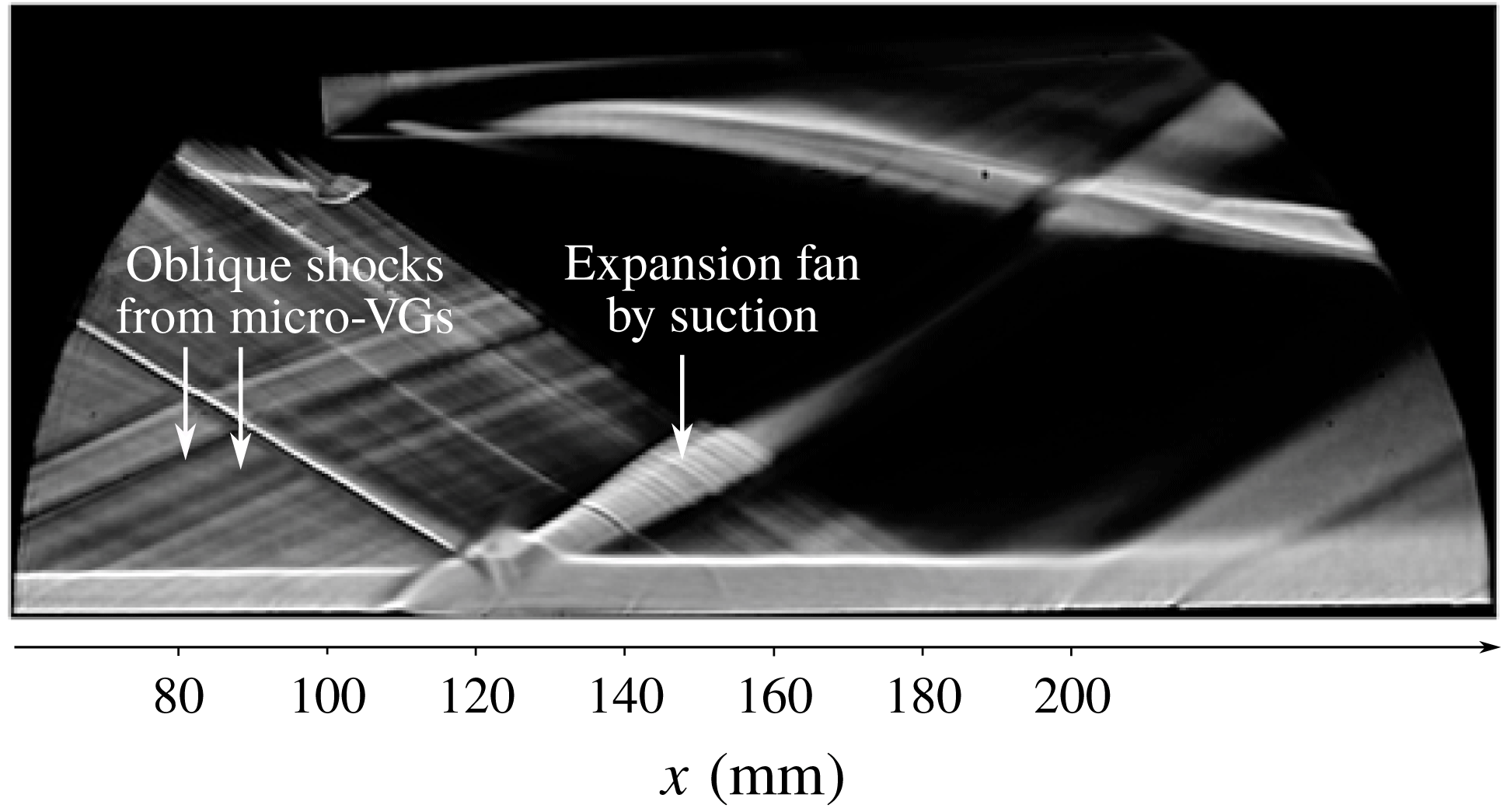
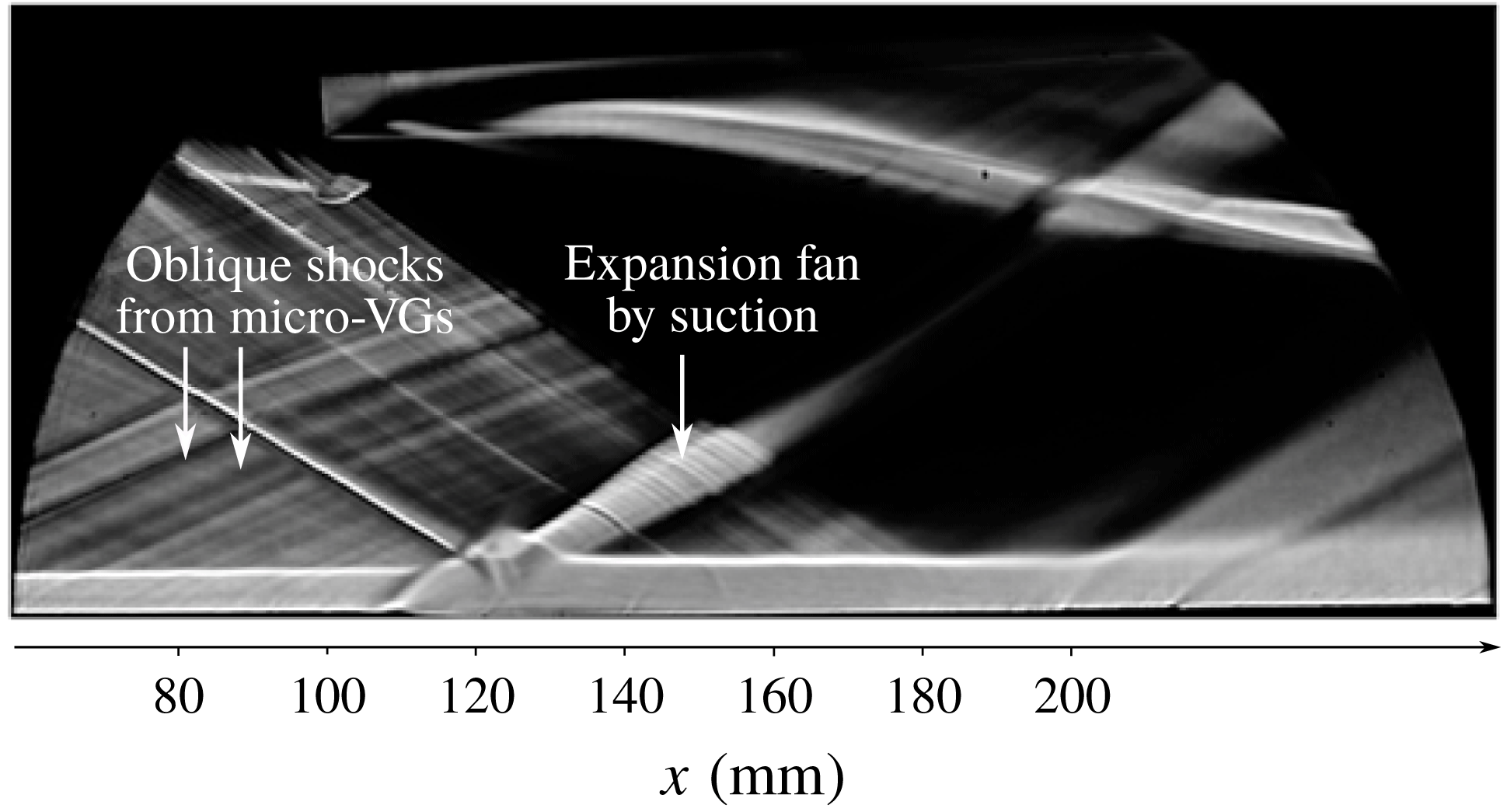
Figure 11 shows a schlieren image for a flow where a combination of micro-VGs (
 $x_{vg}=50~\text{mm}$
) and corner suction (
 $x_{slot}=100~\text{mm}$
) has been used to reduce the size of corner separation. Here, no prominent difference from the baseline flow can be observed except for some evidence of an expansion fan originating from the suction slots and the oblique shock waves created by the leading and trailing edges of the VGs. The main SBLI appears unaffected by the changes to the corner flow.
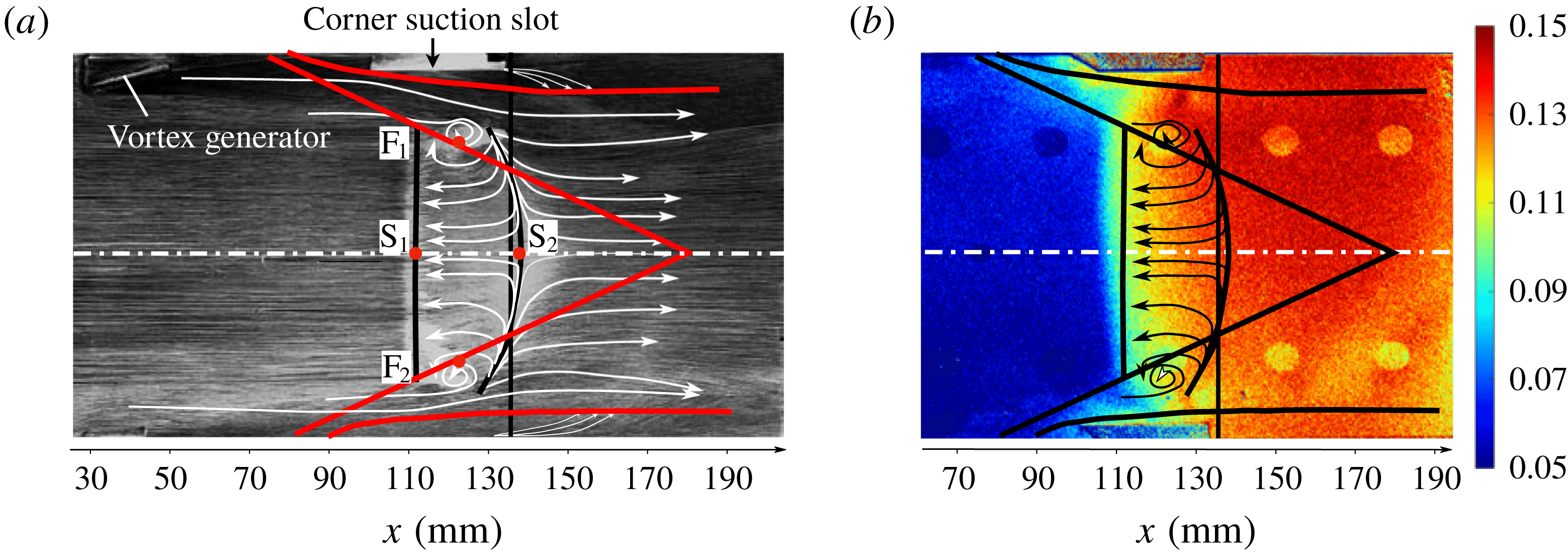
Figure 12(a) provides the oil-flow visualisation. It can be seen that the corner separations are considerably reduced, spanning only 8 mm, which is a 65 % decrease from the baseline. The three-dimensionality of the overall flow field is also reduced. The spanwise extent of the central separation
 $L_{f}$
is now 72 mm (16 % greater than that of baseline) while
 $L_{sep}$
remains unchanged at 25 mm. This is also reflected in the surface pressure distribution presented in figure 12(b), which exhibits a wider region with little spanwise variation at the start of the interaction and reduced pressure smearing near the sidewalls. The corner shock footprint traced by the PSP map suggests that the waves cross at
 $x=181~\text{mm}$
, 21 mm downstream from the uncontrolled case. It is also noteworthy that on the oil-flow image this footprint passes through the two focal points bounding the centreline separation, and that the region in between the corner waves is characterised by relatively straight separation and reattachment lines. The central separation topology can still be classified as an ‘owl-face of the first kind’.
A configuration employing micro-VGs at
 $x_{vg}=50~\text{mm}$
alone is also tested, resulting in a flow field somewhere between the previous two cases, and the relevant geometric measurements are also included in table 1. Tables 2 and 3 summarise the boundary layer profile data upstream and downstream of the interaction for all cases discussed so far. It can be seen that there is very little difference, confirming that corner effects did not change the flow on the centreline in these locations. The main effect of reducing the size of corner separation is therefore an increase in the uniform main interaction region while the central separation length is unaffected. Such quasi-two-dimensional behaviour has also been observed in the large-eddy simulations of Wang et al. (Reference Wang, Sandham, Hu and Liu2015) for relatively large wind-tunnel widths, where the corner shocks determined by the pressure gradient contours are shown to reach the symmetry plane well behind the interaction zones.
Summary of separation-related parameters for reduced corner effects.

Boundary layer parameters at
 $x=80~\text{mm}$
along the tunnel floor centreline for baseline and the experiments with reduced corner separations.

Boundary layer parameters at
 $x=160~\text{mm}$
along the tunnel floor centreline for baseline and the experiments with reduced corner separations.

3.3 Interaction with increased corner separations
Schlieren photographs with corner obstacle introduced to increase corner effects: (a) streamwise position of the block front edge at
 $x_{block}=120~\text{mm}$
; (b) streamwise position of the block front edge at
 $x_{block}=75~\text{mm}$
.
Surface oil-flow visualisation on the tunnel floor for the oblique SBLIs with increased corner effects: (a)
 $x_{block}=130~\text{mm}$
; (b)
 $x_{block}=125~\text{mm}$
; (c)
 $x_{block}=120~\text{mm}$
; (d)
 $x_{block}=115~\text{mm}$
; (e)
 $x_{block}=105~\text{mm}$
; (f)
 $x_{block}=95~\text{mm}$
; (g)
 $x_{block}=90~\text{mm}$
; (h)
 $x_{block}=85~\text{mm}$
; (i)
 $x_{block}=85~\text{mm}$
with elongated blocks at a length of 40 mm; and (j)
 $x_{block}=75~\text{mm}$
. The approximate footprint of the corner shock is indicated by red lines.
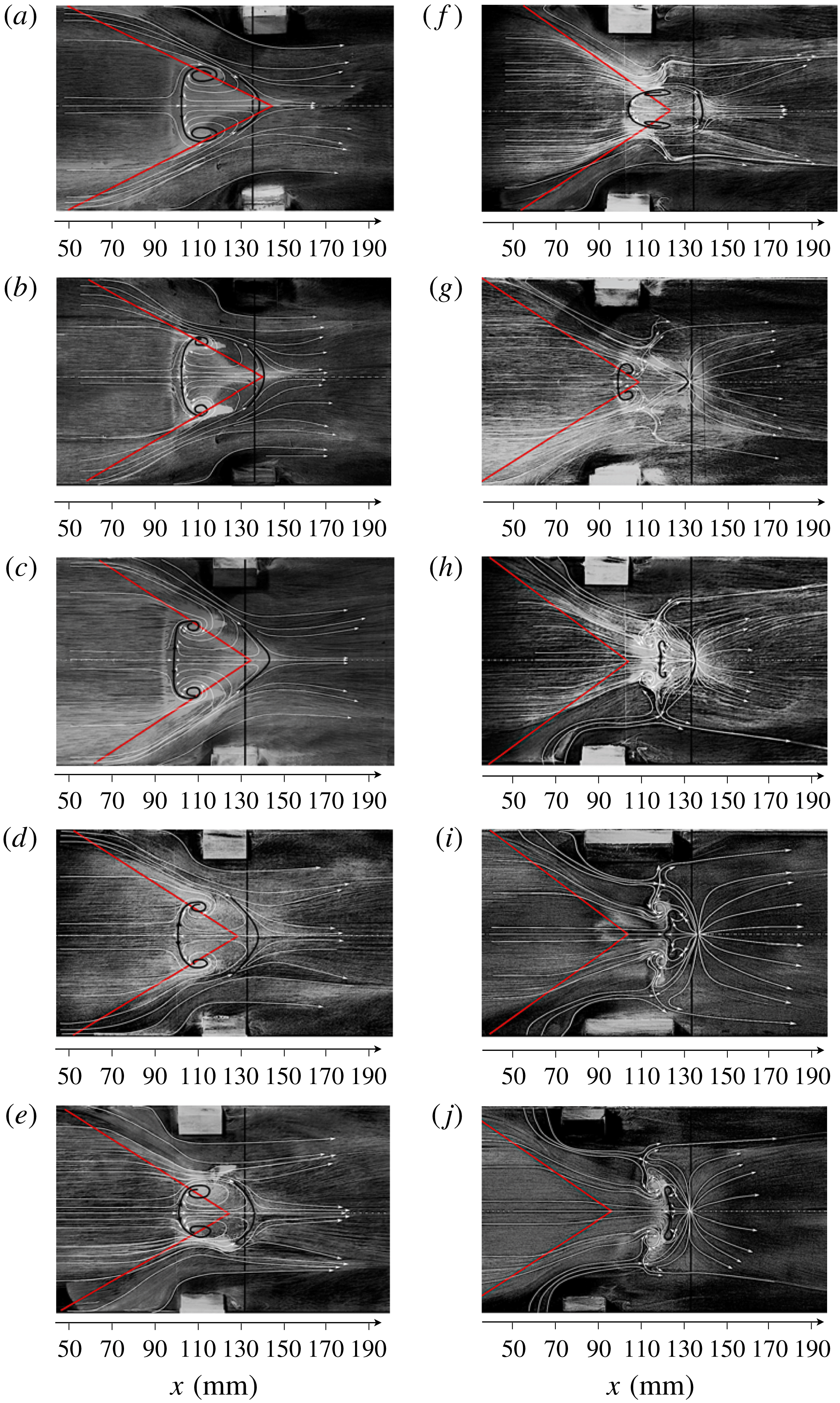
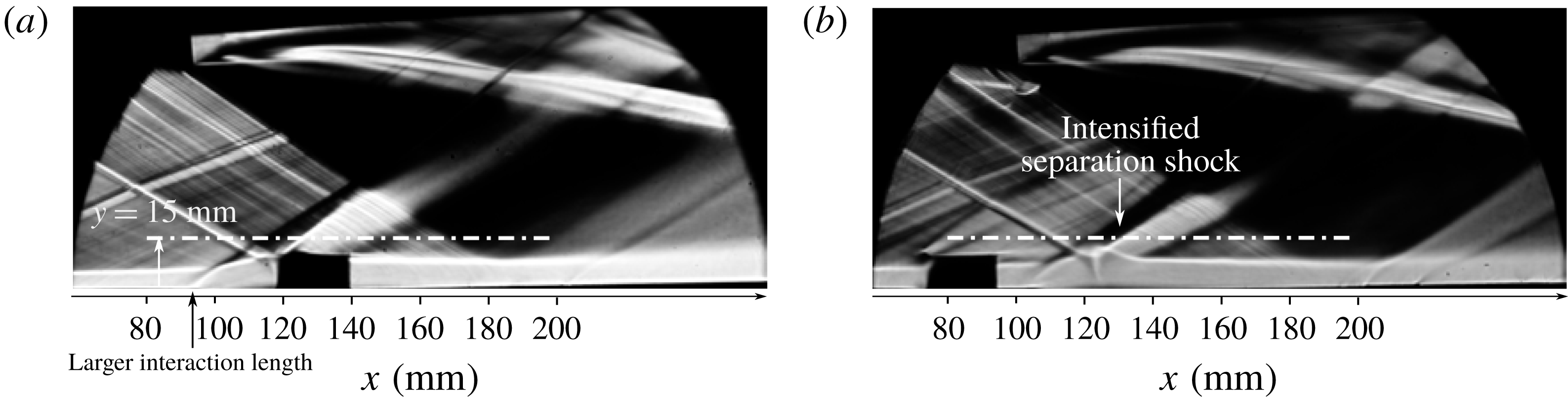
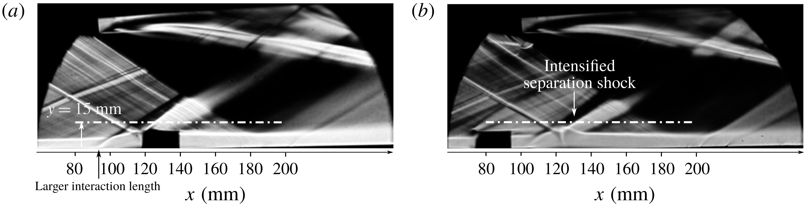
Figure 13 shows schlieren images for two experiments where corner blocks are applied to increase the size of corner separations. The horizontal white dot-dashed lines represent the position at which streamwise LDA traverses are conducted. Figure 13(a) presents the flow with the corner obstacles placed across the interaction domain at
 $x_{block}=120~\text{mm}$
. A much larger interaction length with an onset
 $20~\text{mm}$
upstream of the unmodified SBLI is observed, and the boundary layer downstream of the interaction appears to be thicker than in the baseline flow. Both observations suggest that the oblique shock-induced separation has increased in size. In contrast, when the blocks are located even further upstream, at
 $x_{block}=75~\text{mm}$
(figure 13
b), the separation shock is more pronounced while the size of the interaction zone exhibits no prominent difference compared to the undisturbed SBLI.
Summary of separation-related parameters for increased corner effects.
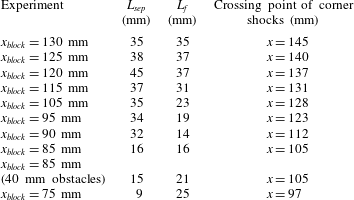
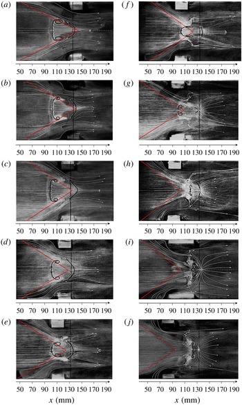
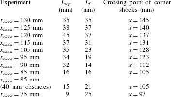
A series of oil-flow images with various corner-block positions are shown in figure 14. Compared to the baseline surface streamline pattern (figure 7 a), it can be seen that for all corner-block locations the corner separations are significantly increased in size by up to 50 %. As the blocks move upstream, the onset of corner separation shifts forwards as well and the corner shock footprints (and the approximate crossing points) are found to move accordingly (as indicated by the red lines). This is accompanied by significant changes in the size and shape of centreline separation, as shown by the geometric parameters in table 4.
Figure 14(a–g) shows that when the corner waves cross inside the separated region, the centreline separation length
 $L_{sep}$
experiences a sharp increase. More specifically, the value of
 $L_{sep}$
reaches a maximum when the intersection point approaches the reattachment position of the unmodified SBLI at
 $x=137~\text{mm}$
, as shown in figure 14(c). Here the separated flow reattaches further downstream than in any of the other tests. This is followed by a progressive decrease in
 $L_{sep}$
as the corner shock intersection point moves upstream. Owing to the more prominent displacement effect caused by enlarged corner separations, corner shocks are located increasingly closer to the mid-span symmetry line and hence affect a larger proportion of the flow field. This is reflected by a change in the spanwise extent of the central separation, which clearly shows a trend of decreasing as the corner shocks move upstream. The central separation topology is also observed to transit from ‘owl-face of the first kind’ to the more complicated ‘second kind’ (as seen in figure 15
a,b), with the approximate footprint of the corner shocks once again crossing through the focal points identified at the edges of centreline separation.
As the crossing point of corner shocks shifts ahead of the separated zone (figure 14
h–j), the trend of reducing separation length continues, even beyond the baseline. For the most upstream location of the corner blocks, the centreline separation length reduces to 9 mm, which is a 64 % decrease from the baseline value. Closer inspection reveals that the reduction in
 $L_{sep}$
is due to a delayed separation onset, while the reattachment location remains approximately unchanged from the undisturbed interaction. The topological structure of the central separation is seen to exhibit a more complicated pattern. As shown in figure 15(c), an additional pair of saddle points (S
 $_{1}$
, S
 $_{2}$
) and foci (F
 $_{1}$
, F
 $_{2}$
), respectively, are observed in the upstream portion, while the rest of the flow field closely resembles an ‘owl-face of the second kind’. The more extensive corner separations deflect the flow near the sidewalls toward the mid-span more strongly. This, along with a reduced centreline separation distance, gives rise to an additional pair of vortices, which act to help the flow accumulated in the central region lift off and escape from the tunnel floor. In this case, the spanwise width
 $L_{f}$
is defined as the distance between F
 $_{3}$
and F
 $_{4}$
, the two focal points inside the shock-induced separated region.
Surface flow topology of the centreline separation underneath the oblique SBLIs with increased corner effects: (a) crossing point of corner shocks downstream from the separation onset of baseline flow; (b) crossing point at the separation onset of baseline flow; (c) crossing point upstream of the separation onset of baseline flow.
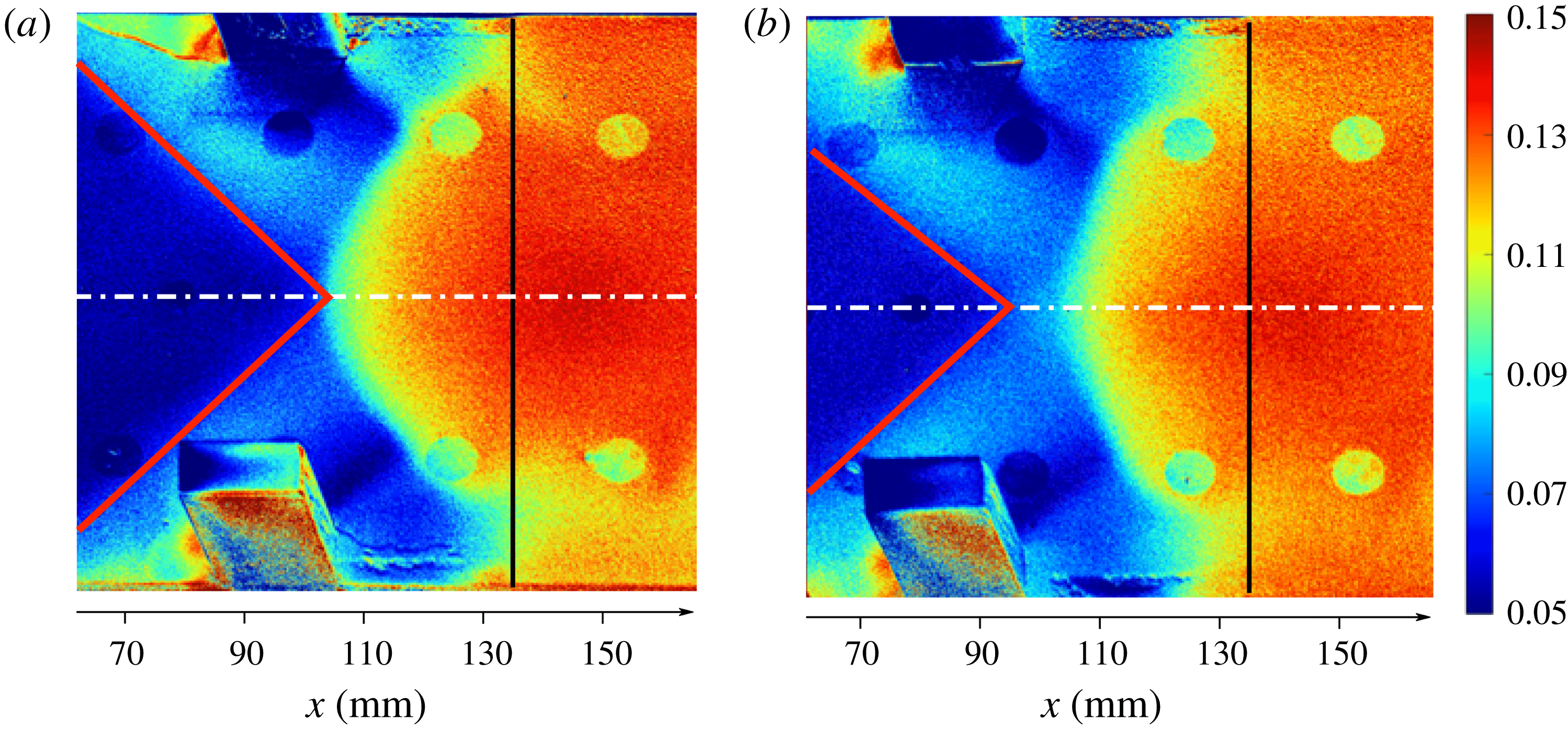
In figure 16 the static wall pressure distribution on the tunnel floor is shown for the two corner-block experiments with reduced
 $L_{sep}$
. Compared to the baseline flow (figure 8
a), the corner shock footprint covers a larger area ahead of the main interaction. As a result of the more upstream position of corner shocks, there is no longer a uniform flow region directly ahead of the interaction domain.
Static wall pressure distribution
 $P/P_{0}$
for the tunnel floor for the oblique SBLIs with increased corner effects: (a)
 $x_{block}=85~\text{mm}$
; (b)
 $x_{block}=75~\text{mm}$
. The approximate footprint of the corner shock is indicated by red lines.
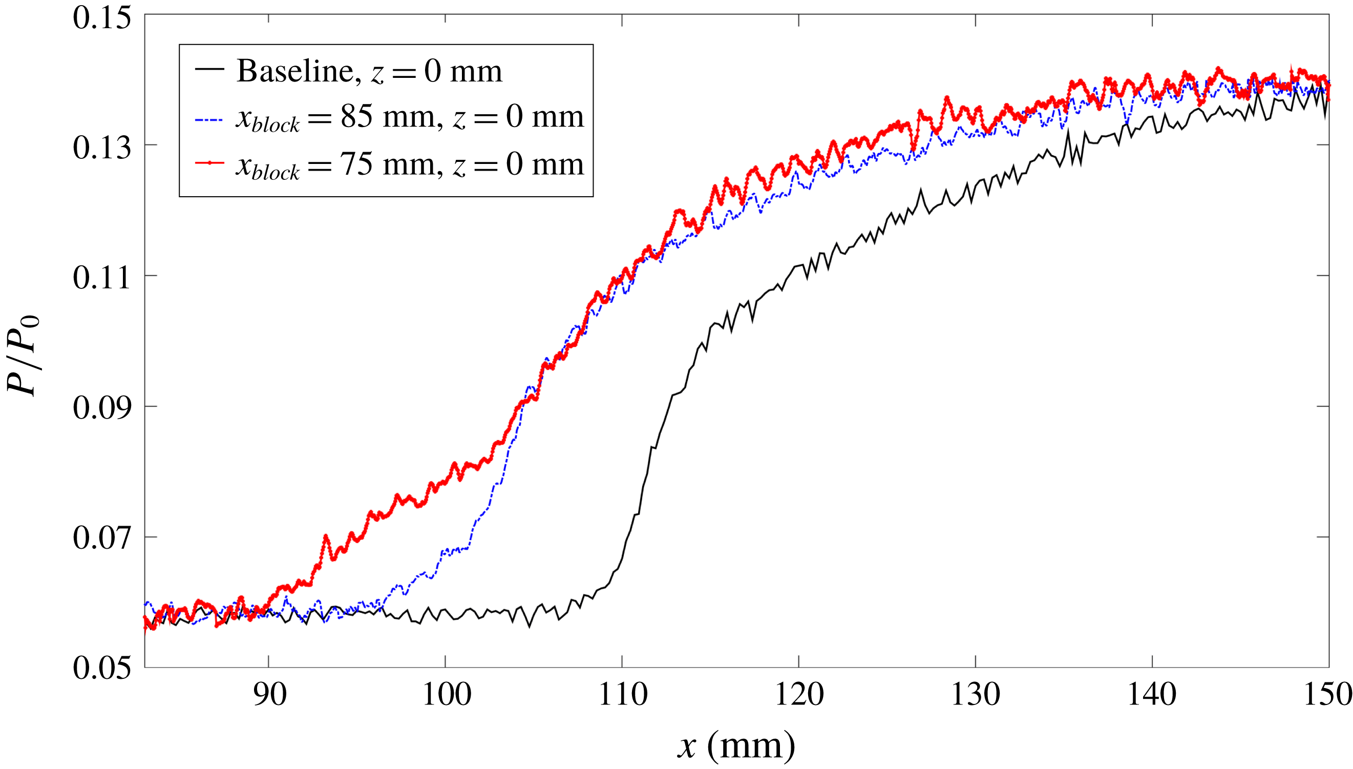
Static wall pressure distribution on the tunnel floor centreline.
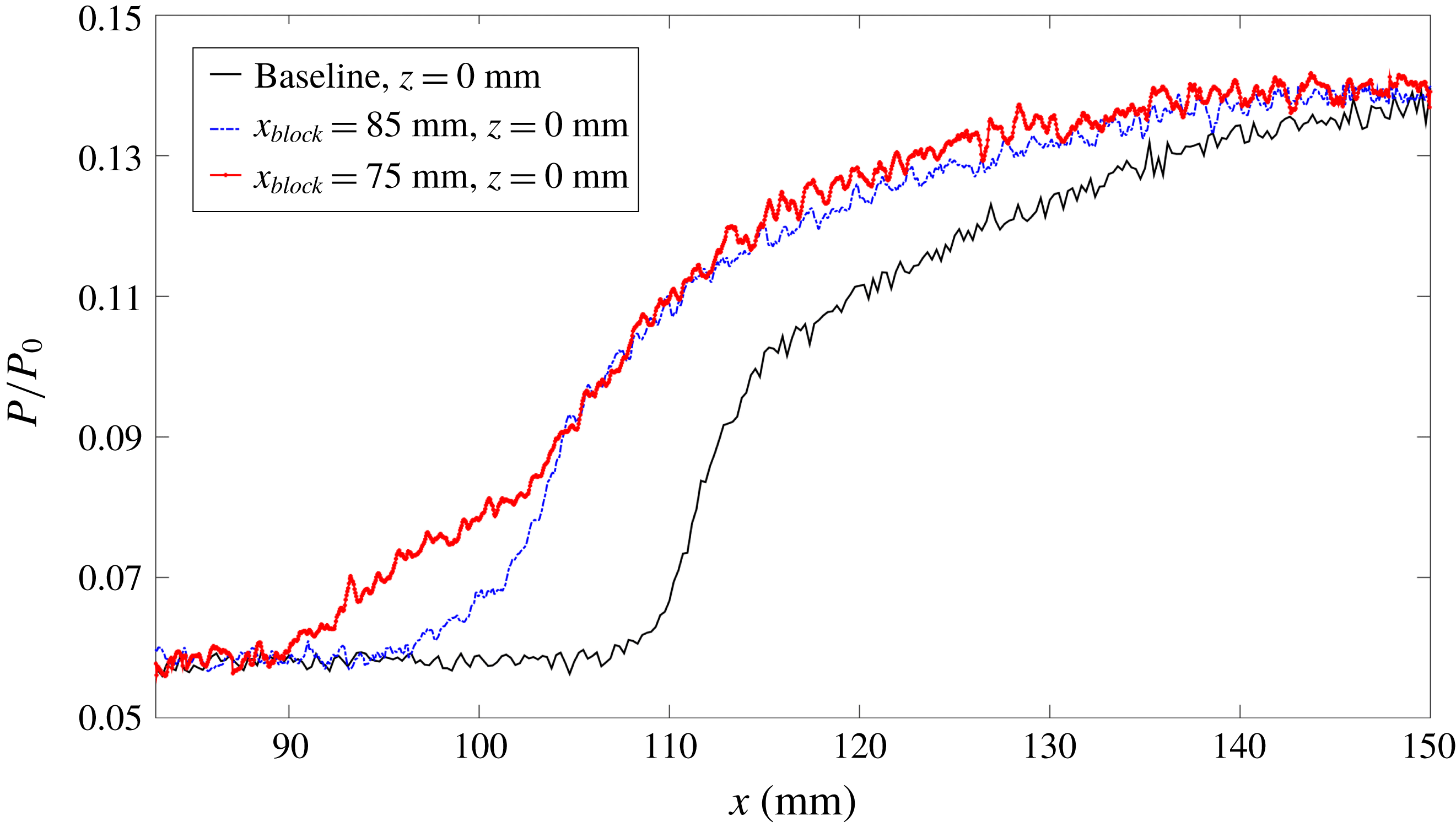
Figure 17 compares selected wall pressure distributions along the tunnel floor centreline. The
 $x_{block}=85~\text{mm}$
case shows an increased upstream influence, with the pressure rise occurring approximately 12 mm earlier than in the baseline flow. This is followed by a less steep APG across the interaction and an unchanged total shock-induced pressure rise. For the
 $x_{block}=75~\text{mm}$
experiment, the upstream influence is further increased with the onset of pressure rise located 20 mm upstream compared to the baseline, exhibiting a larger interaction length with a noticeably milder APG. If the centre-span flow behaved quasi-two-dimensionally, the larger interaction length would be associated with an increase in centreline separation. This, however, contradicts the considerably reduced
 $L_{sep}$
shown in the oil-flow images (figure 14
h,j), suggesting that the increase in pressure smearing is not caused by the local separation ‘bubble’ but rather is a consequence of the changes to the corner wave positions and their influence on the centreline flow.
The inflow boundary layer parameters along the tunnel floor centreline are listed in table 5. The data for the configuration
 $x_{block}=75~\text{mm}$
are not available, as this block position obstructs the laser light path. In all cases, the inflow boundary layer parameters are almost unchanged from the baseline. This confirms that the corner obstacles, located well away from the tunnel mid-span, do not affect the centre-span flow ahead of the interaction.
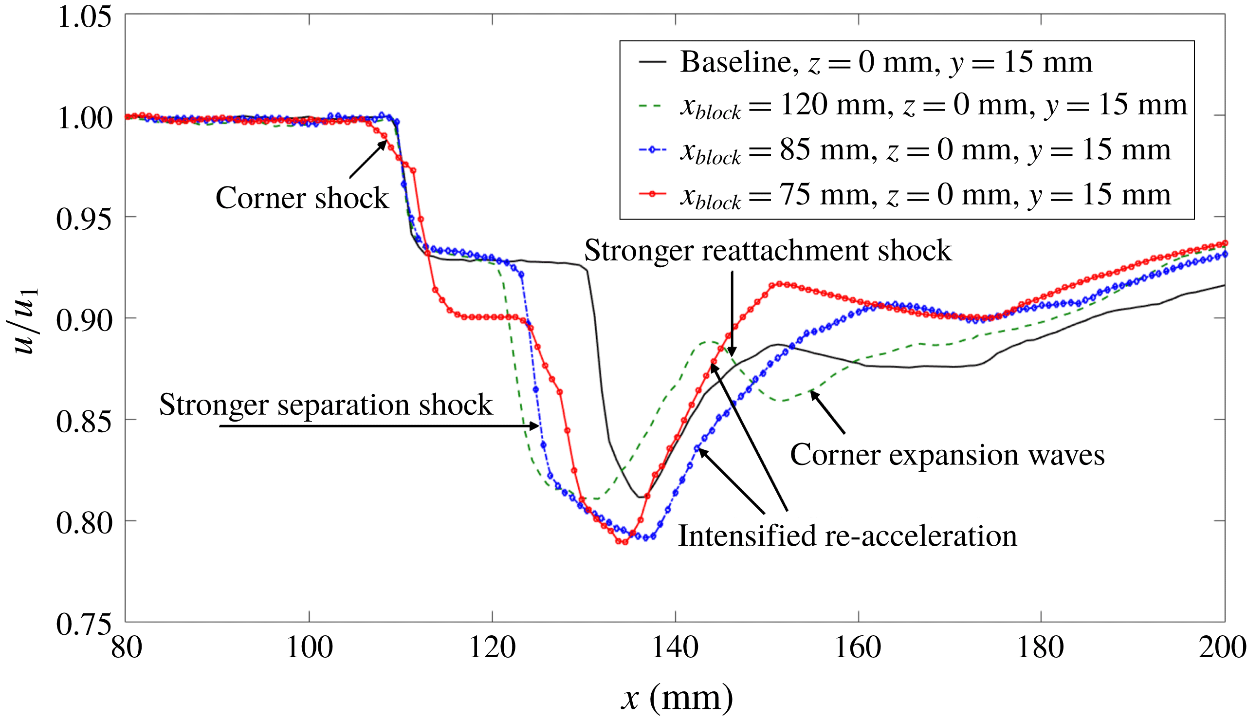
Variation in streamwise velocity at
 $y=15~\text{mm}$
,
 $z=0~\text{mm}$
.
Boundary layer parameters at
 $x=80~\text{mm}$
along the tunnel floor centreline for the experiments with increased corner separations.

Boundary layer parameters at
 $x=160~\text{mm}$
along the tunnel floor centreline for the experiments with increased corner separations.
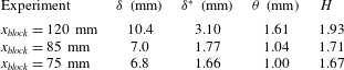
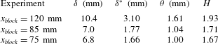
Table 6 compares the boundary layer parameters measured 25 mm downstream of the inviscid shock reflection point. A much thicker boundary layer is seen in the
 $x_{block}=120~\text{mm}$
experiment (also observed in the schlieren visualisation in figure 13
a). This is in accordance with the delayed reattachment process and the largest separation length
 $L_{sep}$
among all the tests. Lower incompressible shape factors are observed for the experiments with the corner blocks applied at
 $x_{block}=85~\text{mm}$
and
 $x_{block}=75~\text{mm}$
, which indicate fuller boundary layer profiles recovering quicker from the effect of the oblique interaction. This is most likely a consequence of the reduced centreline separation.
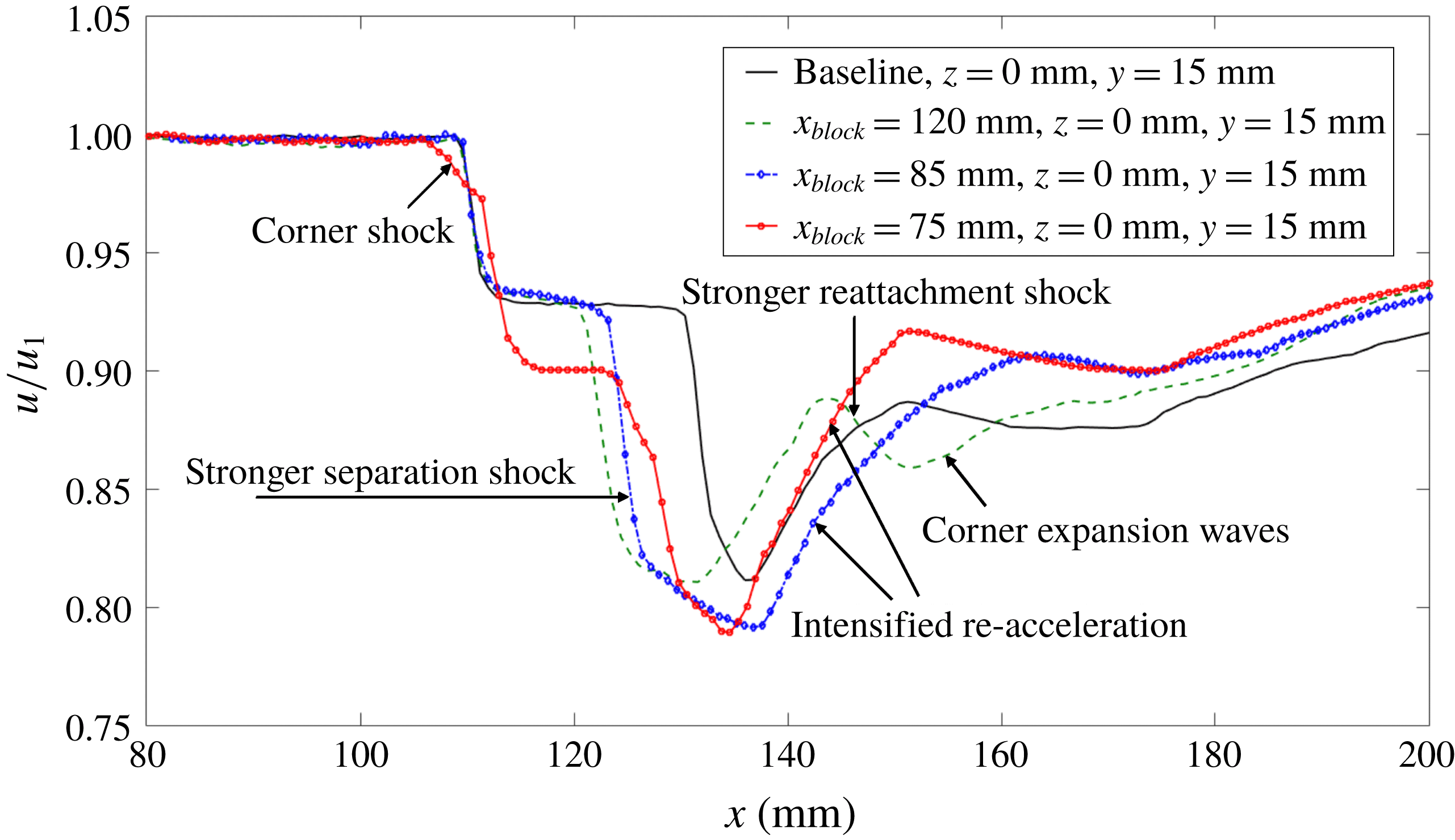
Figure 18 presents the streamwise velocity variation through the impinging SBLI above the boundary layer edge at
 $y=15~\text{mm}$
,
 $z=0~\text{mm}$
. The measurements show that the deceleration through the separation shock occurs approximately 10 mm further upstream in the three corner-block tests than in the baseline experiment, in line with an increased interaction length and an earlier onset of pressure rise. For the
 $x_{block}=120~\text{mm}$
test, the flow deceleration through the reattachment shock is more pronounced, indicating that the strength of the pressure rise is intensified by the corner shock waves which reach the symmetry line at this location (see also the approximate footprint of the corner shocks marked in figure 14
c). The expansion waves generated by the corner separation can be seen in the flow acceleration downstream of the reattachment shock. In the
 $x_{block}=85~\text{mm}$
experiment where corner shocks arrive ahead of the centreline separation, the flow is decelerated to a lower velocity than the baseline case through the combined effects of the corner and separation shocks. This is followed by a more pronounced re-acceleration caused by the subsequent corner expansion waves, which also meet inside the interaction zone. For the case of
 $x_{block}=75~\text{mm}$
, an additional velocity reduction occurs ahead of the incident shock. This is due to the corner shocks being shifted further upstream, now located approximately 30 mm (5 times inflow
 $\unicode[STIX]{x1D6FF}$
) ahead of the centreline separation onset, as shown in figure 14(j). The following deceleration of the incident shock appears to be almost the same as for the baseline case. A similar intensified re-acceleration is again observed.
Schematic illustration of corner effects on the oblique SBLIs with increased corner effects along the symmetry line: (a) corner shocks cross inside the centreline separation; (b) corner shocks cross ahead of the centreline separation.
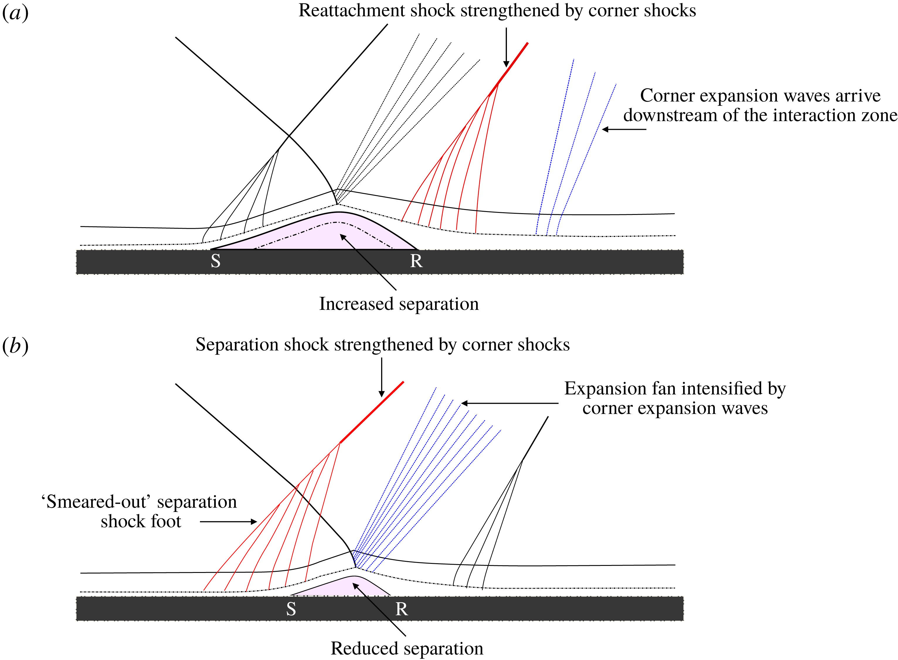
The effect of the corner waves on the SBLI in the central plane is shown schematically in figure 19. Figure 19(a) describes interactions where the corner shock crosses around the reattachment region (e.g.
 $x_{block}=120~\text{mm}$
). In this scenario, the reattachment shock is strengthened by the corner shocks. Thus, the pressure rise at reattachment is intensified, which requires an increased separation bubble size to accommodate the greater overall pressure jump across the interaction. The subsequent corner expansion waves, which might relieve the additional pressure rise, however, arrive too far downstream to cancel the effects of the corner shocks before reattachment (as shown in figure 18). This leads to the increased separation length observed in the oil-flow visualisation (figure 14
c) and a downstream shift of the reattachment line compared to the baseline flow. The enlarged centreline separation then gives rise to an increased interaction domain, which explains the earlier onset of deceleration through the separation shock compared to the baseline case (figure 18).
An equivalent schematic illustration for the interaction where the corner shocks are even further upstream and cross ahead of the separated region is provided in figure 19(b). Here the corner shocks reach the centreline before the separation point. The additional pressure rise caused by the corner shock might be expected to increase the central separation, whereas the evidence (figure 14
h,j) shows the opposite behaviour. This can be explained by two factors. First, the corner ‘shock’ is of relatively limited strength and consists of a series of compression waves rather than a single strong shock. This means that the overall pressure jump is smeared over a larger area. Second, the corner shock is followed by expansion waves which now reach the symmetry plane within the interaction zone (as seen in figure 18 by the strong re-acceleration of the flow above the interaction region for
 $x_{block}=85~\text{mm}$
and
 $x_{block}=75~\text{mm}$
). This means that they can now relieve the overall pressure rise, which reduces the separation length.
As the corner expansion waves play a significant role in the physical mechanism proposed for the interactions with reduced
 $L_{sep}$
, an additional experiment has been conducted with obstacles of a different length to test whether the prominent corner expansion waves seen here are induced by the corner separation or the rear edge of the block. The oil-flow visualisation shows that
 $L_{sep}$
of the flow disturbed by the elongated obstacles (figure 14
i) is almost the same as that altered by the standard blocks (figure 14
h), confirming the corner expansion fan emanating from the tunnel sidewall is a consequence of the displacement effect of the corner separation.
3.4 Discussion
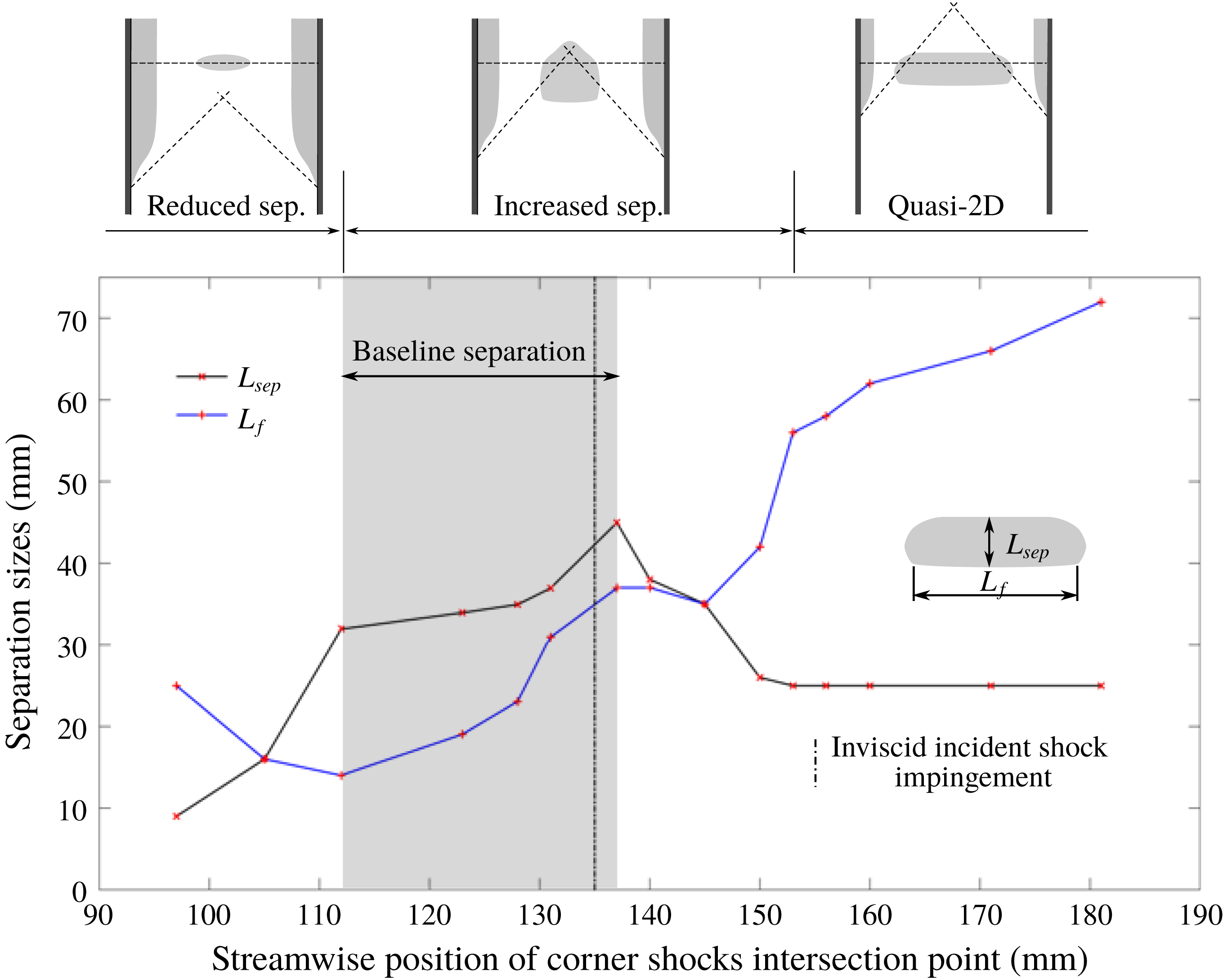
Variation of the centreline separation length
 $L_{sep}$
and width
 $L_{f}$
as a function of streamwise position of corner shock intersection point.
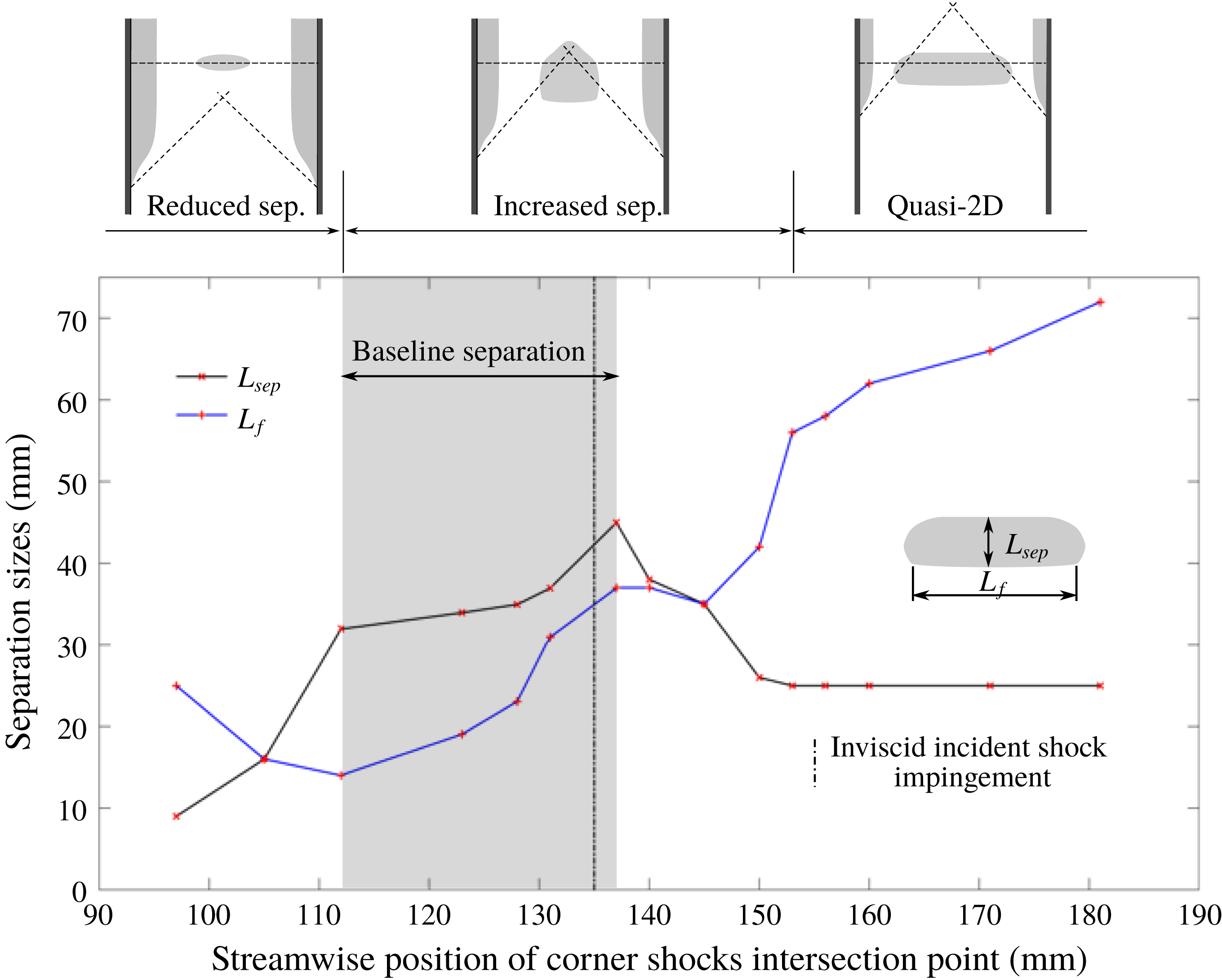
In the above it has been shown that modifications to the size of corner separations have a direct effect on the location of corner shock and expansion waves. The position of the corner shock crossing point (found by approximating the corner compression waves by a straight line) is a good indication of the impact of the corner waves on the size and shape of the central separation. If the crossing point falls downstream of the interaction, the separation on the centreline is unaffected. If the crossing point falls inside the interaction zone, the separation is increased, while a crossing point ahead of the interaction leads to a reduction in central separation. This behaviour is well illustrated by figure 20, which shows the separation length measured on the symmetry line
 $L_{sep}$
as a function of the corner shock crossing point for all experiments conducted. As a guide, the extent of the baseline separation is also given. For corner shock crossing points downstream of the interaction, there is no influence on the separation length and the central separation is at its most ‘two-dimensional’. It can be seen that the largest separation is observed when the corner shocks cross near the end of the baseline separation. This is likely to be because no beneficial expansion waves can reach the interaction in this scenario. As the shock crossing point moves upstream, more expansion waves help to gradually alleviate the detrimental effects of the corner shocks until eventually the influence of compressions and expansions on the interaction reverses and the separation length reduces even beyond the nominal two-dimensional value. This is aided by the more gentle ‘pre-compression’ from the corner compression waves now arriving ahead of the interaction to reduce the overall APG. The change in streamwise separation length due to corner effects is significant, with the largest separation being five times greater than the smallest. The spanwise extent of the central separation
 $L_{f}$
presents a general trend of decreasing as the crossing point shifts upstream until it moves outside the separated region, where the central separation expands wider in spanwise direction with the corner shock intersection point located further upstream.
4 Conclusion
Experiments have been conducted to study an oblique shock wave/boundary layer interaction in a rectangular cross-section supersonic wind tunnel. The inflow Mach number is 2.5 and a flow deflection of
 $8^{\circ }$
is generated by a wedge mounted at the ceiling. The adverse pressure gradient (APG) resulting from the oblique shock reflection on the floor of the working section is sufficient to cause substantial separations both in the corners and around the central span. The magnitude and onset of corner separations are modified with flow control to produce corner effects varying in relative size from moderate to significant.
The results demonstrate that changes to the geometry of corner separation can strongly affect the size and shape of separation observed in the centre of the tunnel floor. A decrease in the size of the corner separation generates a more two-dimensional flow field with the central separation having a greater spanwise extent. An increase in the size of the corner separation drastically changes the surface flow topology of the separated region in the centre, which is observed to transit from the quasi-two-dimensional ‘owl-face of the first kind’ to the more complicated second kind. The separation length measured along the symmetry line is also seen to be considerably altered, presenting an increasing and then decreasing trend as the onset of corner separation shifts upstream.
The primary mechanism behind this appears to be the waves induced by corner separations, which act to alter the separated interaction wave structure and in turn influence the APG imposed upon boundary layers elsewhere. The blockage effect of the corner separation first deflects the supersonic flow away from the corner through a series of compression waves, or ‘corner shock waves’, and then returns the flow towards the streamwise direction by an expansion fan. The impact of these corner waves on the central separation is found to be well illustrated by the position of the corner shock crossing point. If the corner shocks reach the symmetry plane downstream of the interaction zone, the centreline separation is unaffected. If the crossing point is inside the separated flow, an increase in separation length and a more three-dimensional separation bubble can result because of the detrimental effect of the corner shocks. In cases where the corner shocks are shifted further upstream and intersected ahead of the interaction, a reduction in centreline separation length even beyond the two-dimensional value is observed due to the beneficial effect of the corner expansion waves.
The experimental conditions tested show that the presence of corner effects can cause the centreline separation length to vary from 36 % to 180 % of the nominally two-dimensional baseline value. The results illustrate the significance of corner effects for oblique SBLIs in rectangular channels.
While the current study has investigated only one particular free-stream Mach number and oblique shock strength, it is the authors’ view that the fundamental wave interactions and their effect on the overall flow topology are similar for all oblique shock reflections, and this allows a few basic ‘predictions’. Given that the corner shock crossing point has been identified as a critical parameter, it is suggested that interactions with greater Mach-number inflows are likely to exhibit more ‘two-dimensional’ behaviour, as the wave angle would be expected to decrease with increasing Mach numbers. On the other hand, stronger shock strengths are expected to increase the size of corner separations, which would lead to a more upstream position of the corner waves and thus promote more ‘three-dimensional’ interactions.
The footprint of the corner shocks has also been applied to the surface flow visualisation of previous numerical studies with different wedge angles, Mach numbers and aspect ratios, such as those performed by Wang et al. (Reference Wang, Sandham, Hu and Liu2015) and Benek, Suchyta & Babinsky (Reference Benek, Suchyta and Babinsky2016). The relative position of the corner shock crossing point and the main interaction domain are shown to capture the extent of sidewall effects, and correctly predict the general behaviour of central separations. This suggests the generality of the experimental findings, which can be tested by future research for different shock strengths and incoming boundary layer conditions.