1 Introduction
The Richtmyer–Meshkov instability (RMI) develops when a corrugated interface separating two different fluids is impulsively accelerated by a shock wave. This flow instability phenomenon was studied first theoretically by Richtmyer (Reference Richtmyer1960) and later experimentally by Meshkov (Reference Meshkov1969). The RMI has become increasingly significant in many areas of scientific research such as inertial confinement fusion (ICF) (Lindl et al. Reference Lindl, Landen, Edwards, Moses and Team2014) and astrophysical problems (Remington et al. Reference Remington, Kane, Drake, Glendinning, Estabrook, London, Castor, Wallace, Arnett and Liang1997). The nature of geometrical convergence in converging RMI makes the perturbation development more complicated for the existence of the Bell–Plesset (BP) (Bell Reference Bell1951; Plesset Reference Plesset1954) and Rayleigh–Taylor (RT) effects (Fincke et al. Reference Fincke, Lanier, Batha, Hueckstaedt, Magelssen, Rothman, Parker and Horsfield2004; Lombardini & Pullin Reference Lombardini, Pullin and Meiron2014). Because phenomena existing in a spherical geometry also occur in a cylindrical geometry and the latter offers ease of diagnostics from the experimental point of view (Mikaelian Reference Mikaelian2005), shock tube experiments on the cylindrical RMI are greatly desired for understanding the real circumstance of ICF. However, most previous works have focused on the planar RMI because it is difficult to generate a cylindrically converging shock wave in an ordinary shock tube.
There are only a small number of works on the cylindrically converging shock and, consequently, fewer shock tube experiments on the converging RMI. The first feasible experimental generation of a cylindrically converging shock wave was achieved by Perry & Kantrowitz (Reference Perry and Kantrowitz1951) in a horizontal annular shock tube with a coaxial teardrop-shaped inner core. This method was later adopted by Kjellander, Tillmark & Apazidis (Reference Kjellander, Tillmark and Apazidis2011) to determine the self-similar constant for cylindrically converging shocks. An annular, vertical, strut-free, diaphragmless shock tube was designed and manufactured by Hosseini, Ondera & Takayama (Reference Hosseini, Ondera and Takayama2000). The interaction of a cylindrically converging shock wave with a cylindrical interface was studied in this vertical shock tube and the growth of the interfacial thickness was discussed (Hosseini & Takayama Reference Hosseini and Takayama2005). A similar annular vertical shock tube, but using different methods of interface generation and flow diagnostics, was constructed to study the cylindrically converging shock wave interacting with polygonal interfaces (Si et al. Reference Si, Long, Zhai and Luo2015). Besides, a gas lens technique was proposed by Dimotakis & Samtaney (Reference Dimotakis and Samtaney2006) to convert a planar shock wave into a cylindrical one, and a preliminary experiment on the interaction of the converging shock wave with a sinusoidal disturbed interface was reported (Biamino et al. Reference Biamino, Jourdan, Mariani, Houas, Vandenboomgaerde and Souffland2015). However, due to the influence of double membranes, little quantitative information on RMI was acquired. Based on the shock dynamics theory, a curved wall is specially designed and manufactured to gradually transform a planar shock wave into a perfectly cylindrical one (Zhai et al. Reference Zhai, Liu, Qin, Yang and Luo2010). In the converging test section, experiments of cylindrically converging shock waves interacting with a gas bubble and gas cylinder were successfully performed (Si, Zhai & Luo Reference Si, Zhai and Luo2014). These attempts successfully revealed the evolution process of flow structures induced by RMI, which demonstrates the great potential of the shock tube technique for studying the converging RMI. Recently, the interaction of a converging shock wave with a single-mode interface was demonstrated in a semi-annular shock tube (Luo et al. Reference Luo, Ding, Wang, Zhai and Si2015) and the perturbation growth was quantitatively studied for different initial amplitudes by high-speed schlieren photography (Ding et al. Reference Ding, Si, Yang, Lu, Zhai and Luo2017). These authors reported a quick drop of the amplitude growth rate caused by the RT stabilization effect and proposed a reduction factor in the linear theory to account for the flow compressibility.
In this work, shock tube experiments of a sinusoidal interface interacting with a cylindrically converging shock are performed. The converging shock wave is generated in the vertical coaxial diaphragmless shock tube (Si et al.
Reference Si, Long, Zhai and Luo2015) and four single-mode air/SF
 $_{6}$
interfaces with different initial amplitudes or wavenumbers are generated using an extended soap film technique (Wang et al.
Reference Wang, Yang, Wu and Luo2015). The laser sheet imaging technique is used to capture the flow structure and interface evolution. It is expected that this quantitative study would provide a better understanding of the converging RMI.
2 Experimental methods
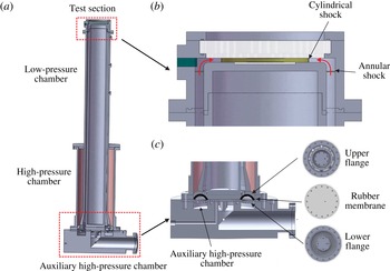
The vertical annular diaphragmless shock tube has already had its feasibility and reliability for generating a cylindrically converging shock verified in our previous work (Si et al. Reference Si, Long, Zhai and Luo2015) and, therefore, only a brief description of this facility is given here. As shown in figure 1(a), the shock tube mainly consists of a test section (detail in figure 1 b), an inner low-pressure driven section, an outer high-pressure driver section and an auxiliary high-pressure chamber (detail in figure 1 c), from top to bottom. The key component is the ring-shaped rubber membrane which is mounted between two bulging metal grid flanges connecting the driver and driven sections. Prior to each experiment, both the driver section and the auxiliary high-pressure chamber are charged by high-pressure air. The pressure in the auxiliary chamber is higher than that in the high-pressure section such that the rubber membrane is pressed onto the upper grid flange and separates the high-pressure section from the low-pressure section. When the diaphragm bursting happens at the exit of the auxiliary high-pressure chamber, the rubber membrane quickly moves to the lower grid flange due to the rapid pressure drop, and thus the high-pressure gas in the driver section immediately exhausts to the driven section. In this way, an annular shock wave propagates in the driven section and smoothly transforms into a cylindrical shock wave in the test section along the rounded junction between the test section and the driven section. The uniformity of the converging shock when it is approaching the converging centre has been checked in our previous work by examining the schlieren images (Si et al. Reference Si, Long, Zhai and Luo2015).
Schematic diagrams of the vertical coaxial diaphragmless shock tube (a), the test section (b) and the auxiliary high-pressure chamber (c).

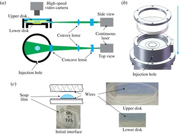
Schematic diagrams of the planar Mie scattering photography from top and side views (a), the assembling of the components of the test section (b) and the device for interface formation (c).

The flow visualization uses planar Mie scattering photography, as sketched in figure 2(a). The optical system, consisting of a cylindrical concave lens and a convex lens, forms a laser sheet (thickness of 0.5 mm) for illuminating the flow field through the symmetry plane of the test section as detailed in figure 2(b). A continuous high-power laser (SDL-532-15000T, Shanghai Dream Lasers technology Co. Ltd., 15 W, 532 nm) is used as the light source. A high-speed video camera (FASTCAM SA5, Photron Limited) is employed to record the light scattered by the TiO
 $_{2}$
micro-particles and soap droplets from the break-up of the soap film after the incident shock passage. The average size of the soap droplets and TiO
 $_{2}$
micro-particles is estimated to be approximately
 $1{-}10~\unicode[STIX]{x03BC}\text{m}$
. In all experiments, the frame rate of the camera is chosen to be 62 500 frames per second, corresponding to a time interval between two consecutive frames of
 $16~\unicode[STIX]{x03BC}\text{s}$
. The shutter rate of the camera is set at
 $1/517000$
s and the spatial resolution is approximately
 $0.18~\text{mm}~\text{pixel}^{-1}$
.
As shown in figure 2(b), the test section includes two disks for interface formation. The wire restriction soap film technique developed in our laboratory (Wang et al.
Reference Wang, Yang, Wu and Luo2015) is extended to form the single-mode gas interface. As illustrated in figure 2(c), two circular grooves with a shape of
 $r(\unicode[STIX]{x1D703})=R_{0}+a_{0}\cos (n\unicode[STIX]{x1D703})$
, where
 $R_{0}$
is the radius (20.0 mm in this work),
 $a_{0}$
the initial amplitude and
 $n$
the wavenumber, are first engraved on the two Plexiglass disks with a thickness of 3.0 mm. Then two Plexiglass wires with the same shape as the groove are embedded into the two grooves. The bulge of the wires is approximately 0.2 mm in height, which is far smaller than the height of the test section (5 mm). The two Plexiglass disks are mounted in the test section and reinforced by two quartz glasses (35.0 mm in thickness) from the upper and lower visualizing windows. The surface of each disk surrounded by the circular wire is first wetted uniformly by the soap liquid (made of 78 % distilled water, 2 % sodium oleate and 20 % glycerine by mass), and a small injection tube is then placed inside the wire-enclosed circle on the lower disk through a hole on the side wall to supply the test gas (i.e. SF
 $_{6}$
and TiO
 $_{2}$
micro-particle mixture). The soap bubble becomes a hemisphere bounded by the wire on the lower disk and then expands to the upper disk. When the soap bubble almost completely contacts the wire on the upper disk, the injection tube is taken off and the hole is sealed. As the density of SF
 $_{6}$
is much greater than that of air, it is easier for air to permeate into the soap film. Therefore the soap bubble will keep on swelling after the injection tube is taken off. When the soap bubble just completely contacts the wire on the upper disk, the pressures inside and outside the soap bubble are equal to each other and the experiment is ready to run. As the width of the wire is 0.5 mm, the difference of the average radius along the vertical direction is less than 2.5 %. Therefore, it can be concluded that the extended soap film technique can form an almost ideal two-dimensional cylindrical sinusoidal interface.
3 Experimental results
3.1 Unperturbed gas cylinder
We first consider an air/air cylindrical interface (inner air mix with TiO
 $_{2}$
smog,
 $R=20$
mm) subjected to the cylindrically converging shock. The propagation of a converging shock wave obeys a self-similarity solution,
 $$\begin{eqnarray}\frac{r}{R_{0}}=\left(1-\frac{t}{t_{0}}\right)^{\unicode[STIX]{x1D6FC}},\end{eqnarray}$$
where
 $r$
is the shock location at time
 $t$
, according to Guderley’s theory (Guderley Reference Guderley1942; Ponchaut et al.
Reference Ponchaut, Hornung, Pullin and Mouton2006). Note that Guderley’s theory was derived for a strong cylindrically converging shock wave. As discussed in Si et al. (Reference Si, Long, Zhai and Luo2015), however, some experiments (Takayama, Kleine & Groenig Reference Takayama, Kleine and Groenig1987; Kjellander et al.
Reference Kjellander, Tillmark and Apazidis2011) indicated that the value of
 $\unicode[STIX]{x1D6FC}$
is heavily dependent on the adiabatic exponent and could remain stable over a wide range of incident shock Mach numbers. In this experiment,
 $R_{0}=19.84$
mm is taken as the radius of shock position near the initial interface and
 $t_{0}=38.2~\unicode[STIX]{x03BC}\text{s}$
is the travelling time of the converging shock from
 $R_{0}$
to the converging centre, which is calculated from the air/air experimental data fitted by the method of least squares. A similarity constant
 $\unicode[STIX]{x1D6FC}=0.834\pm 0.016$
of the converging shock is obtained from the high-speed images, which agrees well with the theoretical similarity constant of 0.835 in air. In addition, the incident shock velocity (
 $v_{i}$
) when the wave front contacts the gas cylinder is approximately
 $433.2~\text{m}~\text{s}^{-1}$
. Both the similarity constant and the shock velocity at the interface approximately coincide with values in our previous work (Si et al.
Reference Si, Long, Zhai and Luo2015). This verifies the reliability of the shock tube facility and also indicates that the TiO
 $_{2}$
micro-particles follow the flow nicely and, therefore, have little influence on the flow features.
The flow field behind a converging shock is non-uniform as the converging shock travels to the geometry centre (Lombardini & Pullin Reference Lombardini, Pullin and Meiron2014). Therefore, an unperturbed cylindrical air/SF
 $_{6}$
interface (i.e. a circular cylinder) is considered to obtain the flow characteristics after the shock–interface interaction. The time when the converging shock meets the interface is defined as
 $t=0~\unicode[STIX]{x03BC}\text{s}$
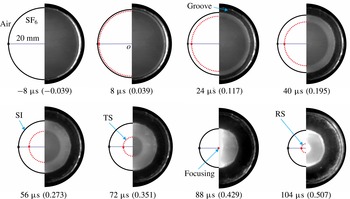
in this work. As illustrated in figure 3, the transmitted shock (TS) and the shocked interface (SI) can be identified clearly after the converging shock interacts with the circular interface (
 $t=8~\unicode[STIX]{x03BC}\text{s}$
). The SI moves towards the convergence centre following the TS. An outgoing shock is reflected when the TS focuses at the geometry centre (
 $t=88~\unicode[STIX]{x03BC}\text{s}$
) and will inevitably interact with the evolving interface (i.e. reshock) at
 $t_{r}=146~\unicode[STIX]{x03BC}\text{s}$
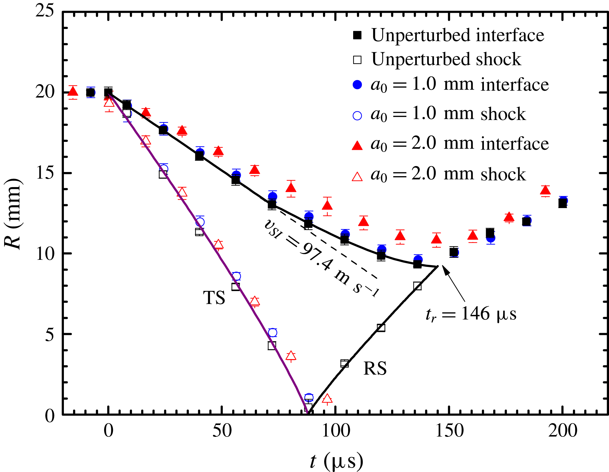
. After the reshock, the interface starts to move outwards. The displacements of shocks and the shocked interface are extracted from the images as shown in figure 4 together with those in two single-mode cases. At the resolution shown, it appears that the converging shock remains symmetric about the geometry centre.
Evolution of an initially unperturbed air/SF
 $_{6}$
interface interacting with a cylindrically converging shock. SI: shocked interface, TS: transmitted shock, RS: reflected shock. The time interval between two consecutive frames is
 $16~\unicode[STIX]{x03BC}\text{s}$
. The time when the converging shock meets the interface is defined as
 $t=0~\unicode[STIX]{x03BC}\text{s}$
. Numbers inside brackets are dimensionless times based on a characteristic time of
 $t_{c}=205.3~\unicode[STIX]{x03BC}\text{s}$
.

Displacements of the shock and the shocked interface for the unperturbed and single-mode cases. The time when the converging shock meets the interface centre is defined as
 $t=0~\unicode[STIX]{x03BC}\text{s}$
. The initial velocity of the shocked interface (SI) is
 $v_{SI}=97.4~\text{m}~\text{s}^{-1}$
. TS: transmitted shock, RS: reflected shock. The reshock time is calculated as
 $t_{r}=146~\unicode[STIX]{x03BC}\text{s}$
based on experimental data points.

The TS moves with nearly the same velocity for all the cases, which verifies the repeatability of the shock tube facility. Therefore, the flow characteristics of the unperturbed case can be used for the analysis of the single-mode case, such as the maximal compression rate
 $R_{0}/R_{min}$
, which is 2.16, with
 $R_{min}$
being the minimum value (9.6 mm) of the interface radius and where the incident shock meeting the circular interface has a strength of
 $Ma=1.29$
. The speeds of the interface and the shock just after the interaction are calculated to be
 $v_{SI}=97.4~\text{m}~\text{s}^{-1}$
and
 $v_{TS}=198.5~\text{m}~\text{s}^{-1}$
, respectively. The characteristic time
 $t_{c}$
can be defined as
 $t_{c}=R_{0}/v_{SI}=205.3~\unicode[STIX]{x03BC}\text{s}$
. The one-dimensional gas dynamics theory is applied to obtain the initial parameters of the gas mixture as listed in table 1. The Atwood number
 $A$
, defined as
 $A=(\unicode[STIX]{x1D70C}_{2}-\unicode[STIX]{x1D70C}_{1})/(\unicode[STIX]{x1D70C}_{1}+\unicode[STIX]{x1D70C}_{2})$
with
 $\unicode[STIX]{x1D70C}_{1}$
and
 $\unicode[STIX]{x1D70C}_{2}$
being respectively the fluid densities inside and outside the interface, is
 $-0.62$
.
Physical properties of the gas mixture (air/SF
 $_{6}$
system) calculated by one-dimensional gas dynamics theory at
 $T_{0}=298$
K and
 $p_{0}=101\,325$
Pa for all cases studied in this work;
 $\unicode[STIX]{x1D70C}$
is the gas mixture density,
 $\unicode[STIX]{x1D70E}$
is the sound speed of the gas mixture and
 $\unicode[STIX]{x1D6FE}$
is the specific heat ratio of the gas mixture.

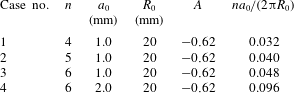
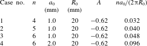
The values of various quantities for the four single-mode interfaces:
 $n$
, the wavenumber of the single-mode interfaces;
 $a_{0}$
, the initial amplitude of the single-mode interfaces;
 $R_{0}$
, the average radius of the interface;
 $A$
, Atwood number of the two fluids around the initial interface;
 $na_{0}/(2\unicode[STIX]{x03C0}R_{0})$
, the ratio of the perturbation amplitude of the initial interface to the wavelength.
We also note that the moving velocity of the shocked interface is continuously decreasing after the interaction. This deceleration has also been reported in experiments on the OMEGA laser and the semi-annular shock tube, which would cause the RT effect (Lanier et al. Reference Lanier, Barnes, Batha, Day, Magelssen, Scott, Dunne, Parker and Rothman2003; Ding et al. Reference Ding, Si, Yang, Lu, Zhai and Luo2017). The deceleration can be calculated by taking a second derivative of the interface trajectory, which will be used for evaluating the RT effect on single-mode interfaces later.
3.2 Single-mode interface
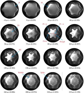
Four single-mode interfaces are studied in the present work and the values of various quantities for the initial single-mode interfaces are provided in table 2. Figure 5 shows one typical evolution of the perturbed air/SF
 $_{6}$
interface (
 $a_{0}=2.0$
mm and
 $n=6$
) accelerated by the converging shock, in which positions of shock and interface can be easily distinguished. The converging shock compresses the initial interface when it meets the interface, and then the incident shock completely transmits into the SF
 $_{6}$
and possesses a sinusoidal wave front. The perturbation amplitude of the interface starts to grow and the whole interface moves inwards and twists violently. With the TS approaching the geometry centre, the shape of the wave front gradually changes from a sinusoidal one (
 $56~\unicode[STIX]{x03BC}\text{s}$
) to a polygonal one (
 $72~\unicode[STIX]{x03BC}\text{s}$
) and then the TS converges and reflects back. The twisted interface is recompressed by the reflected shock, and the trough starts spraying outward and suppresses the crest, eventually forming a spike structure. The crest almost stays still and transforms into a bubble structure gradually by the opposite baroclinic vorticity caused by the reshock. Finally the interface amplitude starts to grow rapidly and saturates eventually.
Typical evolution of a sinusoidal air/SF
 $_{6}$
interface (
 $a_{0}=2.0$
mm and
 $n=6$
) subjected to a converging shock. II: initial interface, SI: shocked interface, TS: transmitted shock, RS: reflected shock. The time interval between two consecutive frames is
 $16~\unicode[STIX]{x03BC}\text{s}$
. The time when the converging shock meets the interface is defined as
 $t=0~\unicode[STIX]{x03BC}\text{s}$
. Numbers inside brackets are dimensionless times based on a characteristic time of
 $t_{c}=205.3~\unicode[STIX]{x03BC}\text{s}$
.

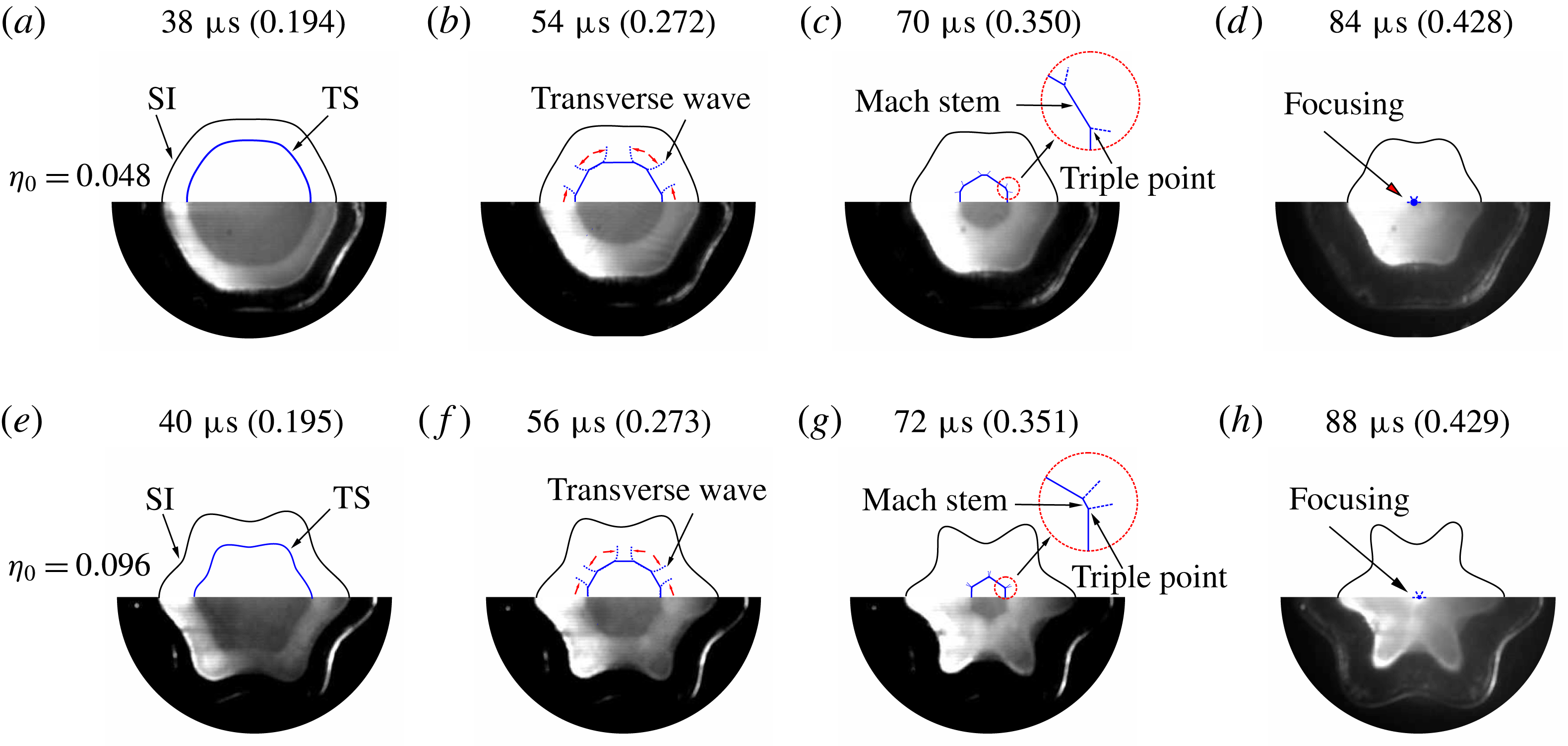
Figure 6 shows detailed observations of the evolution of the wave pattern for Case 3 and Case 4 at four moments before the shock focusing. Right after the incident shock passes through the corrugated interface, the TS almost transforms into the sinusoidal shape as shown in figure 6(a,e). The trough and crest of both the interface and the shock front are in phase at this moment. Gradually, the TS transforms into a dodecagon (figure 6 b,f) and a hexagon (figure 6(c,g) by transverse waves between triple points. Later on, the hexagon shock front gets smaller as it heads toward the geometry centre and finally converges and reflects at the centre (figure 6 d,h). As the shock front is perturbed by the initial interface, the shock front will not focus into a singularity. All the shocked perturbed interfaces share the same evolving pattern, and the characteristic structure is more distinct for the larger-amplitude case.
Evolution of the wave patterns for two interfaces (Case 3 and Case 4) at four moments before the shock focusing. Panels (a–d) are for Case 3 and (e–g) for Case 4. The time when the converging shock meets the interface is defined as
 $t=0~\unicode[STIX]{x03BC}\text{s}$
. Numbers inside rackets are dimensionless times based on a characteristic time of
 $t_{c}=205.3~\unicode[STIX]{x03BC}\text{s}$
;
 $\unicode[STIX]{x1D702}_{0}=na_{0}/(2\unicode[STIX]{x03C0}R_{0})$
is the ratio of the amplitude to the wavelength of the initial interface.

The interface amplitude
 $a(t)=|r_{crest}-r_{trough}|/2$
can be extracted from the images for different initial amplitudes and wavenumbers, where
 $r_{crest}$
and
 $r_{trough}$
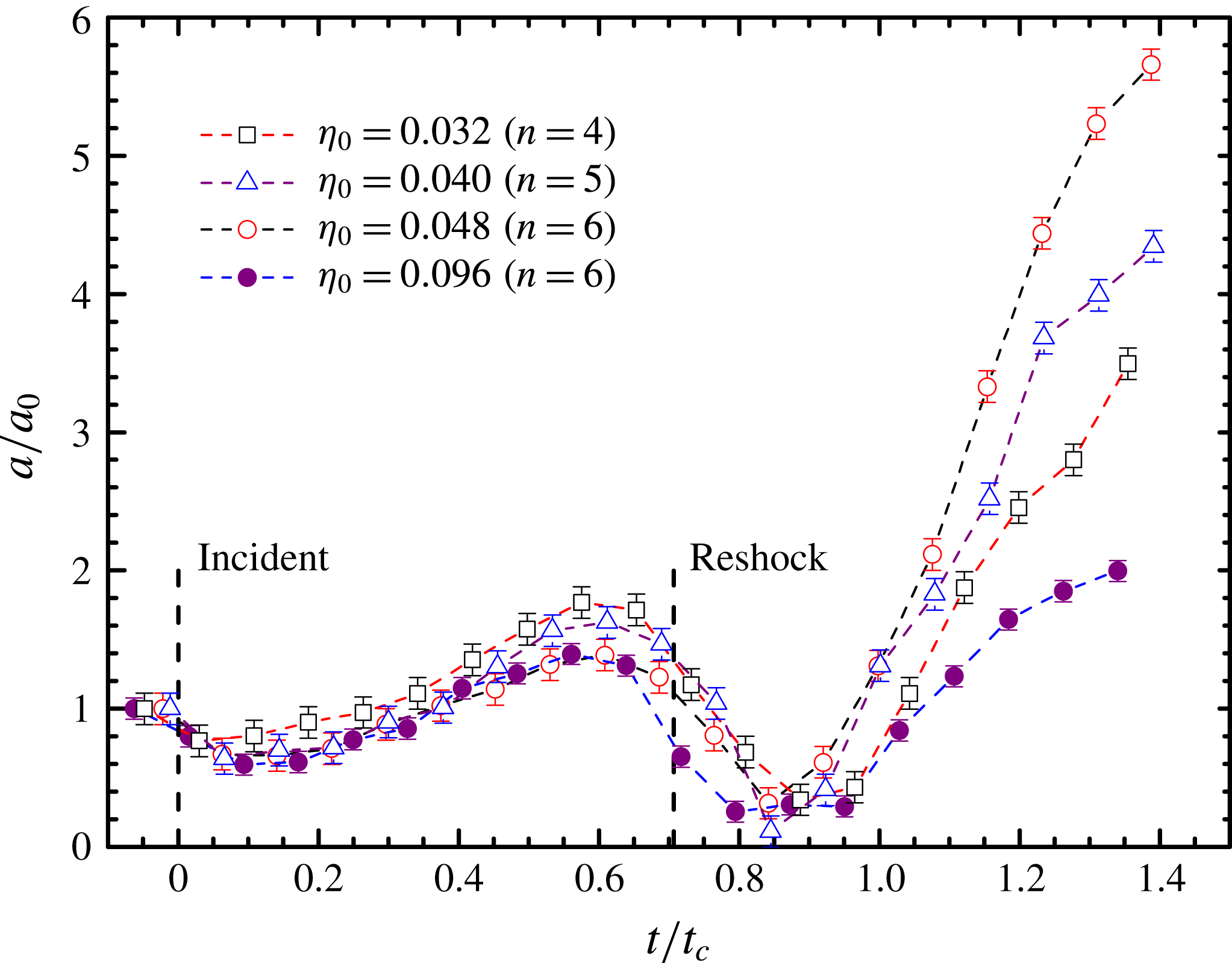
are the radii of the crest and trough shown in figure 5, respectively. Figure 7 plots the amplitude histories for the four sinusoidal interfaces. The amplitude is normalized by its initial value and the characteristic time
 $t_{c}$
is chosen to be the same as that in the unperturbed case, i.e.
 $t_{c}=205.3~\unicode[STIX]{x03BC}\text{s}$
. It is found that the interface amplitude behaves similarly in all four cases: it first decreases, then grows to a maximum, later drops again and finally increases rapidly after the reshock. After the shock compression, the amplitude of the shocked interface enters a quickly growing phase caused by the RMI and BP effects. The reduction of the perturbation amplitude is ascribed to the RT stabilization effect due to the interface deceleration before the reshock (Ding et al.
Reference Ding, Si, Yang, Lu, Zhai and Luo2017). Recompressed by the reshock, the interface amplitude shrinks to a minimum in a very short time, and then increases substantially. It is noted that, for the same initial amplitude (
 $a_{0}=1.0$
mm), the influence of the wavenumber on the amplitude growth is very small before the reshock, but becomes significant after the reshock.
Amplitude development for four single-mode interfaces under the converging RMI.
 $\unicode[STIX]{x1D702}_{0}=na_{0}/(2\unicode[STIX]{x03C0}R_{0})$
is the ratio of the amplitude to the wavelength of the initial interface.

4 Conclusions
The interaction of a cylindrically converging shock wave with a sinusoidal air/SF
 $_{6}$
cylinder is studied for the first time in a vertical annular diaphragmless shock tube by a high-speed laser sheet imaging technique. An unperturbed case is first examined to obtain the characteristics of the converging shock and the shocked interface under the current experimental configuration. For the four sinusoidal interfaces with different amplitudes or wavenumbers, the whole process is clearly observed in the high-speed images. The incident converging shock compresses the initial interface when it meets the interface, and obtains a sinusoidal wave front after it completely transmits into the SF
 $_{6}$
. The perturbation amplitude of the interface starts to grow and the whole interface moves inwards and twists violently. With the transmitted shock approaching the geometry centre, the shape of the wave front gradually changes from a sinusoidal one to a polygon. Then the transmitted shock converges and reflects back, and recompresses the twisted interface, which causes a phase inversion of the interface. During the reshock, specifically, the trough of the interface starts spraying outward and suppresses the crest, and eventually forms a spike structure. Meanwhile, the crest almost stays still and transforms into a bubble structure gradually by the opposite baroclinic vorticity caused by the reshock. Finally the interface amplitude starts to grow rapidly and saturates at last. Quantitatively, we have shown that the RMI, the BP effect and the RT effects govern the whole process in the converging RMI. It is found that the perturbation amplitude first decreases due to the shock compression, then experiences a growth to a maximum value, later drops quickly and finally increases rapidly after the reshock. The reduction of growth rate is ascribed to the RT stabilization caused by the interface deceleration motion which is only present in the converging circumstance. It is noted that the influence of the wavenumber on the amplitude growth is very small before the reshock, but becomes significant after the reshock. This work may be useful for better understanding and modelling the converging RMI.
Acknowledgements
This work was supported by the National Natural Science Foundation of China (nos 11625211 and 11621202) and the Science Challenge Project (no. TZ2016001).