1 Introduction
Flow separation from bluff bodies at moderate and high Reynolds numbers often causes large hydrodynamic forces. Mechanisms that mitigate separation can reduce both time-averaged and fluctuating forces, which is advantageous for many engineered structures and vehicles. Flow separation control has thus been a subject of intense investigative effort for much of the last century, beginning with Prandtl’s description of the boundary layer in 1904.
Active flow separation control involves actuators that consume power (Choi, Jeon & Kim Reference Choi, Jeon and Kim2008) to inject momentum targeted at the boundary layer to control separation and reduce drag (Cattafesta & Sheplak Reference Cattafesta and Sheplak2011). An actuator’s control authority is often highly correlated with its momentum flux or thrust. Seifert (Reference Seifert and King2007) developed several non-dimensional numbers to evaluate actuators, also using a momentum coefficient to compare those with disparate physical mechanisms, such as synthetic jets, moving surfaces, and dielectric barrier discharge plasma actuators.
The vortex shedding of a circular cylinder can be suppressed by the appropriate positioning of a smaller control cylinder in the near wake (Strykowski & Sreenivasan Reference Strykowski and Sreenivasan1990), though only at very low Reynolds numbers. At higher Reynolds numbers, the flow past bluff shapes, as well as lifting airfoils, can be effectively controlled for drag reduction by adding small control cylinders that are rotated rapidly (Modi Reference Modi1997). The control cylinders, when placed in close proximity to a bluff body and rotated at high rates, interact with the separating boundary layer to cause it to reattach and reduce pressure drag. The drag reduction is sensitive to the control cylinder position, diameter, and normalized surface speed,
 $\unicode[STIX]{x1D709}=u_{surf}/U_{\infty }$
. Here,
 $u_{surf}$
is the tip speed of the control cylinder and
 $U_{\infty }$
is the free-stream velocity.
The flow actuator in this case, a rotating cylinder, experiences a lift force in a cross-flow. Prandtl (Reference Prandtl1926) argued, based on a potential flow model, that this lift does not exceed a maximum value that is associated with the upstream and downstream stagnation points merging and then moving into the fluid as a saddle point. Tokumaru & Dimotakis (Reference Tokumaru and Dimotakis1993) present experimental measurements of the lift on a rotating cylinder that exceed Prandtl’s maximum lift by 20 %. Sengupta et al. (Reference Sengupta, Kasliwal, De and Nair2003b ) identify in numerical simulations a temporal flow instability in the wake at high rotation rates. This instability provides a mechanism for vorticity to be shed into the wake and Prandtl’s maximum lift to be exceeded. Vortex shedding at high rotation rates was shown experimentally by Kumar, Cantu & Gonzalez (Reference Kumar, Cantu and Gonzalez2011).
In the flow past a rotating cylinder near a plane wall, the gap width is an important parameter in determining the forces on the cylinder, vortex shedding (Cheng & Luo Reference Cheng and Luo2007) and three-dimensional instability (Rao et al. Reference Rao, Stewart, Thompson, Leweke and Hourigan2011, Reference Rao, Thompson, Leweke and Hourigan2015). In the application of rotating control cylinders to bluff body flow control, Mittal (Reference Mittal2001) found that the gap between the main and control cylinders is a critical parameter and sensitivity to the gap changes with Reynolds number. Mittal (Reference Mittal2003) suggests that the mechanism of the control is the injection of momentum from the outer flow into the wake, and therefore the circulation of the control cylinders is of primary importance. When the gap is large, the interaction will be too small to be effective. Conversely, when the gap is small, sufficient circulation to control the flow will not be generated, indicating the existence of an optimal gap distance.
Water tunnel experiments (Korkischko & Meneghini Reference Korkischko and Meneghini2012) and numerical simulations (Zhu et al. Reference Zhu, Yao, Ma, Zhao and Tang2015) have shown that counter-rotating control cylinders suppress vortex-induced vibrations (VIV) in addition to reducing drag of a larger main cylinder. The simulations additionally showed that the VIV suppression was optimized at a particular configuration of control cylinder rotation rate and position. Rotating cylinders have also been used successfully in closed-loop feedback systems for the suppression of vortex shedding from bluff bodies. Examples can be found in the work by Patnaik & Wei (Reference Patnaik and Wei2002), Beaudoin et al. (Reference Beaudoin, Cadot, Aider and Wesfreid2006) and Muddada & Patnaik (Reference Muddada and Patnaik2010).
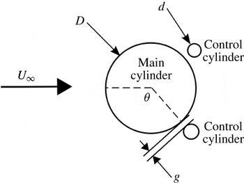
The geometry of both the experiments and numerical simulations presented here includes three bodies. A large main cylinder is accompanied by two smaller counter-rotating control cylinders, which are located symmetrically with respect to a uniform streaming flow. Figure 1 shows a diagram of the arrangement of a main cylinder and control cylinders. The Reynolds number is computed with the main cylinder diameter,
 $D$
, length scale, and kinematic viscosity,
 $\unicode[STIX]{x1D708}$
:
 $Re_{D}=DU_{\infty }/\unicode[STIX]{x1D708}$
.
In this article we address two objectives. The first is a demonstration of the drag reduction of a circular cylinder with rotating control cylinders at
 $Re_{D}=47\,000$
. Modi (Reference Modi1997) reports the results of numerous studies in this Reynolds number range for airfoils and non-circular cylinders. The highest-Reynolds-number studies for the drag reduction of a circular cylinder are the experiments by Korkischko & Meneghini (Reference Korkischko and Meneghini2012) up to
 $Re_{D}=7500$
and the numerical simulations by Mittal (Reference Mittal2001) at
 $Re_{D}=10\,000$
, who noted that the two-dimensional results should be considered an upper bound for the lift of a rotating cylinder in three-dimensional flow. It is therefore important to demonstrate drag reduction at higher Reynolds numbers in experiment or three-dimensional numerical simulations. Here, the flow control is implemented experimentally in a water tunnel at
 $Re_{D}=47\,000$
and measurements of the forces and mean flow are presented. Reynolds numbers with turbulent boundary layers were not achieved with the experimental apparatus, but deserve consideration in the future.
The second objective is to unwrap the effects that the control cylinder diameter, gap to the main cylinder, and rotation rate have on the drag reduction. While both the gap and rotation rate are known to be important design parameters (Mittal Reference Mittal2001, Reference Mittal2003), there are no published studies that investigate different diameters. Here, the flow control is implemented numerically with two-dimensional simulations of the Navier–Stokes equations at
 $Re_{D}=500$
. These simulations were conducted in two dimensions at a low Reynolds number so that a large parameter space could be accurately and efficiently explored, while vortex shedding may occur by both the large and small cylinders. This study includes 60 different configurations of control cylinder diameter,
 $d$
, gap to main cylinder,
 $g$
, and rotation rate,
 $\unicode[STIX]{x1D709}$
.
In a subset of the tested configurations, the wake is stabilized and the flow is steady. In these steady controlled flows, there is a large pressure increase on the main cylinder across the location of the control cylinder, which leads to increased base pressure and reduced drag. By considering many different configurations, a scaling law for the pressure recovery from the separation to reattachment points of the dividing streamline was identified. While the results from the
 $Re_{D}=500$
simulations cannot be used to make quantitative predictions of higher-Reynolds-number flows, they illuminate the importance of viscous stress to the pressure recovery, which is different than previous descriptions of this control mechanism.
The comparison of the low-Reynolds-number simulation with the higher-Reynolds-number experiments provides further insight. The boundary layers are expected to be laminar in both cases, but the wake of the higher-Reynolds-number flow is three-dimensional and turbulent. It is therefore informative to present the results of the experiment alongside the low-Reynolds-number simulations.
Diagram of the flow geometry.

Section 2 describes the experimental methodology and § 3 presents the experimental results. Section 4 describes the numerical methodology and § 5 presents the simulation results. Section 6 discusses the physical mechanism of the separation to reattachment pressure recovery, proposes a new viscous scaling law for the pressure recovery, and finally considers the power consumption and efficiency of the active control.
2 Experimental method
Experiments were conducted in a recirculating water tunnel. An aluminium circular cylinder with outer diameter
 $D=0.0508~\text{m}$
and length
 $L=0.502~\text{m}$
(
 $L/D=9.875$
) was fixed at its centre from the inside to a six-axis force transducer (AMTI MC1). The cylinder nearly spanned the water tunnel test section to mitigate three-dimensional end effects; the gap between the cylinder end and test section wall at both ends was equal to 6.25 % of the main cylinder diameter. Morse, Govardhan & Williamson (Reference Morse, Govardhan and Williamson2008) found that end effects are small for gaps between a cylinder end and an unattached end plate of less than 15 % of the cylinder diameter, which is a similar end condition to a gap to the test section wall. This near-wall end condition was also used in Korkischko & Meneghini (Reference Korkischko and Meneghini2012). The test section is 1.47 m long and the cross-section is
 $0.508~\text{m}\times 0.508~\text{m}$
. The free stream was measured using laser Doppler velocimetry to have a mean velocity of
 $0.925~\text{m}~\text{s}^{-1}$
and free-stream turbulence intensity of 4 %. The cylinder was mounted in the centre of the cross-section and the blockage ratio was 10 %. West & Apelt (Reference West and Apelt1982) report that while blockage ratios of 6–16 % alter the flow patterns compared with free-stream flows, the drag of a circular cylinder is not significantly changed.
Two precision-machined stainless steel shafts served as the rotating control cylinders. The control cylinders were mounted separately from but in close proximity to the main cylinder and spanned the entire test section, being supported by bushings in the test section walls. The control cylinders were rotated by two independent Yaskawa Sigma Mini servo motors. The high-speed motor shafts, rotating at speeds up to 10 000 RPM, penetrated the test section wall through Teflon bushings and coupled coaxially to the control cylinders through low-inertia flexure couplings. The configuration parameters for the water tunnel experiments are listed in table 1.
Configurations tested in the water tunnel experiments (22 in total).

Forces and moments exerted on the main cylinder were monitored with the force transducer installed in-line with the coaxial sting mount. The smaller rotating control cylinders, being supported by bushings in the test section wall and having no contact with the main cylinder or its supporting sting, did not transmit loads to the force transducer. The force measurements therefore reflect the hydrodynamic forces exerted only on the main cylinder and do not include forces exerted on the control cylinders. The drag and lift forces were sampled at 1000 Hz and recorded continuously for 15 min at each rotation rate. This corresponds to over 2000 vortex shedding cycles. The uncertainty in the force measurements is estimated by analysing the standard deviation of the measured time series. Since the forces are unsteady due to vortex shedding at approximately 2.75 Hz, the raw measurements were first filtered using a third-order Butterworth filter with a 10 Hz low-pass cutoff frequency. This filtered signal was subtracted from the raw signal, leaving only noise at frequencies higher than the vortex shedding. The standard deviation of the noise did not exceed 5 % of the mean drag force of the base cylinder without control cylinders.
In addition to force measurements, the mean flow field was measured with two-dimensional planar PIV. A plane normal to the cylinder axis was illuminated with a 532 nm laser sheet. The field of view was 8.19 cm in the stream direction and 14.85 cm in the transverse direction (
 $1.6\times 2.9D$
). A high-speed digital camera was focused on this illuminated plane and video recorded at 1400 frames per second with
 $200~\unicode[STIX]{x03BC}\text{s}$
exposure for 7 s at each control cylinder rotation rate. This 7 s period captured roughly 20 vortex shedding cycles. Velocity fields were computed in DaVis software using a multi-pass cross-correlation algorithm with 128 pixel windows and 50 % overlap. The resolution of the computed velocity vector fields is 5 mm or
 $0.098D$
.
3 Experimental results
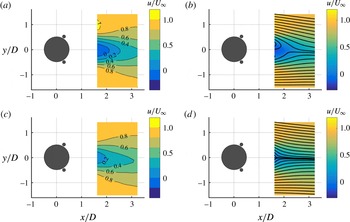
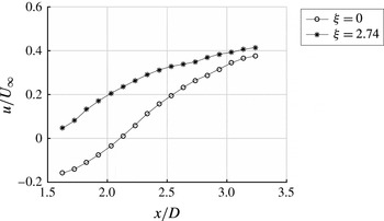
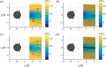
The magnitude of the streamwise component and streamlines of the mean velocity field are shown in figure 2. The contours of the streamwise component of the velocity show that the streamwise momentum deficit in the wake is reduced by rotating the control cylinders with
 $\unicode[STIX]{x1D709}=2.74$
. The wake also narrows, which is apparent in the streamlines. The streamwise component of the velocity along the wake centreline is plotted in figure 3. The recirculation length is equal to the distance along the wake centreline for which the mean streamwise velocity is negative. The recirculation length decreases from
 $2.1D$
in the uncontrolled case to less than
 $1.6D$
when
 $\unicode[STIX]{x1D709}=2.74$
.
Contours of mean streamwise velocity,
 $u/U_{\infty }$
, (a,c) from PIV measurements in water tunnel experiments at
 $Re_{D}=47\,000$
with
 $\unicode[STIX]{x1D709}=0$
(a,b) and
 $\unicode[STIX]{x1D709}=2.74$
(c,d) show that rotating control cylinders reduce the streamwise momentum deficit. Streamlines of the mean flow (b,d) show that the rotating cylinders also narrow the wake.
The streamwise component of the velocity along the wake centreline (
 $y/D=0$
). The recirculation length decreases from
 $2.1D$
to less than
 $1.6D$
when the control cylinders are rotated with
 $\unicode[STIX]{x1D709}=2.74$
.

The drag coefficient,
 $C_{D}$
, is the drag force,
 $F_{D}$
, normalized by the stagnation pressure,
 $1/2\unicode[STIX]{x1D70C}U_{\infty }^{2}$
, where
 $\unicode[STIX]{x1D70C}$
is the density, and the projected area,
 $DL$
:
 $$\begin{eqnarray}C_{D}={\displaystyle \frac{F_{D}}{\frac{1}{2}\unicode[STIX]{x1D70C}U_{\infty }^{2}DL}}.\end{eqnarray}$$
The mean drag coefficient of the main cylinder without control cylinders installed was measured to be
 $C_{D}=1.05$
. This is somewhat lower than the expected value of approximately 1.2 for this Reynolds number (Zdravkovich Reference Zdravkovich1997), possibly due to the relatively high free-stream turbulence intensity of 4 %, as well as the test section wall boundary layers incident on the ends of the cylinder.
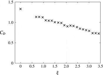
Figure 4 shows
 $C_{D}$
with the control cylinders installed and rotated at different rates. The presence of the control cylinders increases
 $C_{D}$
to 1.33 with
 $\unicode[STIX]{x1D709}=0$
. Korkischko & Meneghini (Reference Korkischko and Meneghini2012) saw an increase in
 $C_{D}$
from 1.21 to 1.51 in a similar arrangement. The drag coefficient decreases approximately linearly with increasing rotation parameter. The highest drag reduction compared with the value with static control cylinders was 45 % at
 $\unicode[STIX]{x1D709}=3.4$
. This drag reduction represents the main cylinder only. The drag of the rotating control cylinders could not be measured with the experimental set-up. The drag of the entire system, including the accompanying rotating control cylinders, may have reduced by a smaller margin due to the contribution of the force on the rotating control cylinders.
In water tunnel experiments at
 $Re_{D}=47\,000$
, the measured mean drag decreases with increasing control cylinder rotation parameter,
 $\unicode[STIX]{x1D709}$
, to
 $55\,\%$
of the base flow drag when
 $\unicode[STIX]{x1D709}=3.4$
.

It is difficult to use PIV to make high-spatial-resolution measurements in the boundary layer and gap between the main and control cylinders because the multiple cylinders obstruct the line of sight of both laser and camera. In addition, conducting experiments with many different configurations is expensive. So, in order to study the flow control mechanism in detail and also to efficiently investigate the sensitivity of the flow control to the configuration parameters, we conduct a series of numerical simulations to supplement these promising experimental results. Two-dimensional simulations at Reynolds number 500 were selected for computational ease, with the anticipation that the mechanisms causing drag reduction are qualitatively similar.
4 Numerical method
The Reynolds number based on the free stream and main cylinder diameter is set to
 $Re_{D}=500$
in these simulations so that both the main and control cylinders would exhibit vortex shedding in isolation. This was verified by observing vortex shedding in a reference simulation of an isolated cylinder with diameter equal to the smallest control cylinder considered in this study, with respect to both
 $Re_{D}$
and to the grid spacing,
 $h$
.
The boundary data immersion method (BDIM), Weymouth & Yue (Reference Weymouth and Yue2011) and Maertens & Weymouth (Reference Maertens and Weymouth2015), was used for these simulations. Cartesian-grid methods are well established at dealing with multiply connected domains (Ye et al.
Reference Ye, Mittal, Udaykumar and Shyy1999) and BDIM has been experimentally validated many times, including for the case of flow past a circular cylinder with
 $Re=100$
by Maertens & Weymouth (Reference Maertens and Weymouth2015). A computational domain having dimensions
 $10D\times 10D$
was used for these simulations. The main cylinder is positioned with distances of
 $4D$
and
 $6D$
, respectively, from its centre to the upstream and downstream boundaries of the domain, and is centred in the direction transverse to the free stream. This domain has a blockage ratio of
 $10\,\%$
, which is identical to the blockage ratio in the water tunnel experiments described in § 2.
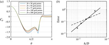
Figure 5 presents the results of a grid convergence study on the base pressure coefficient or pressure coefficient at
 $\unicode[STIX]{x1D703}=180^{\circ }$
, for the configuration with
 $g/D=10\,\%$
,
 $d/D=10\,\%$
and
 $\unicode[STIX]{x1D709}=4$
. The base pressure convergence is second order with
 $h$
and the difference in the solution between the two finest grids is less than 3 %. This demonstrates the convergence of these simulations and the grid with 102.4 grid points spanning the main cylinder diameter is used for this study.
Pressure profile (a) and normalized simulation error of the base pressure (b) for the configuration with
 $g/D=0.01$
,
 $d/D=0.01$
and
 $\unicode[STIX]{x1D709}=4$
with respect to grid resolution. The error is computed relative to the base pressure obtained using a fine
 $D=200h$
reference grid. The solid line indicates second-order convergence with
 $h$
and the dashed line indicates first-order convergence.

The torque,
 $T$
, required to sustain the steady rotation of the control cylinders with angular velocity,
 $\unicode[STIX]{x1D6FA}$
, is balanced by shear stress around the circumference of the control cylinder. The immersed boundary distorts the velocity gradients at the wall, so the torque is computed by integrating the shear stress,
 $\unicode[STIX]{x1D70F}_{\unicode[STIX]{x1D703}}$
, on a circular contour with radius,
 $R_{c}$
, concentric with the cylinder and one grid point larger than the immersed boundary. In these simulations, the immersed boundary extends to a radius of
 $d/2+\unicode[STIX]{x1D716}$
, where
 $\unicode[STIX]{x1D716}=2h$
and
 $h=D/102.4$
. As a result,
 $R_{c}=d/2+\unicode[STIX]{x1D716}+h$
was selected to ensure that the immersed boundary would not affect the computed shear stress:
 $$\begin{eqnarray}T\unicode[STIX]{x1D6FA}=\int _{0}^{2\unicode[STIX]{x03C0}}\unicode[STIX]{x1D70F}_{\unicode[STIX]{x1D703}}(R_{c},\unicode[STIX]{x1D703})u_{\unicode[STIX]{x1D703}}(R_{c},\unicode[STIX]{x1D703})\,\text{d}\unicode[STIX]{x1D703}.\end{eqnarray}$$
The difference between the power consumption of the rotating cylinders computed with (4.1) with the solutions from the two finest grids is 2.3 %.
Simulations were conducted for ranges of control cylinder diameter,
 $d/D$
, gap to main cylinder,
 $g/D$
, and rotation rate,
 $\unicode[STIX]{x1D709}$
. Table 2 shows the configurations of numerical simulations.
Configurations of the numerical simulations (60 in total).

5 Numerical simulation results
5.1 Wake stabilization
The uncontrolled flow past a circular cylinder at
 $Re_{D}=500$
exhibits periodic vortex shedding. All tested cases with stationary control cylinders also exhibited periodic vortex shedding. In contrast, rotating the control cylinders above a critical rate stabilized the wake. The ability of rotating cylinders to stabilize the wake of a main cylinder, especially at low Reynolds numbers, has been shown by Mittal (Reference Mittal2001) and Muddada & Patnaik (Reference Muddada and Patnaik2010).
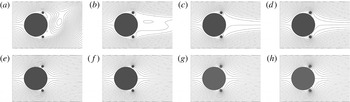
Figure 6 compares instantaneous simulation streamlines from the numerical simulations with those from corresponding potential flow models. The instantaneous viscous flow streamlines show vortex shedding occurs for
 $\unicode[STIX]{x1D709}<3$
and the wake is stable for
 $\unicode[STIX]{x1D709}>3$
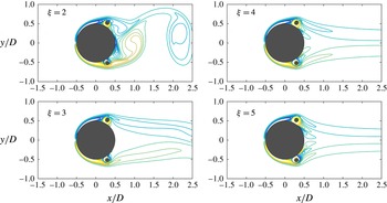
. The streamlines of the higher rotation rate stable viscous flows approach the shape of the streamlines in the potential flow model. The vorticity contours, shown in figure 7, also show the stabilization and narrowing of the wake at higher control cylinder rotation rates.
Streamlines for the viscous simulation (a–d) and a potential flow model (e–h) for rotation parameters, from left to right,
 $\unicode[STIX]{x1D709}=2,3,4$
and
 $5$
. For
 $\unicode[STIX]{x1D709}>3$
, the viscous flow transitions from unsteady vortex shedding to a stable symmetric wake. The streamlines of the stabilized wakes approach the shape of those in the potential flow model.

In both the viscous and potential flows, stagnation points straddle each control cylinder in the configurations with stabilized wakes. The streamlines that connect these stagnation points divide the flow between fluid that recirculates around the control cylinders and fluid that streams into the steady wake.
Instantaneous vorticity contours from the
 $Re_{D}=500$
numerical simulations for various rotation rates of the control cylinders. Higher rotation rates of the control cylinders stabilize and narrow the wake.

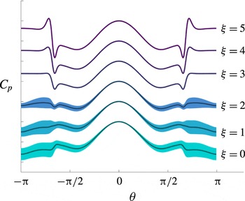
The stabilization of the wake for higher rotation parameters is also apparent in the reduction in variance of pressure on the surface of the main cylinder. Figure 8 shows the root mean square pressure coefficient as a shaded belt around the time-averaged pressure coefficient at different rotation rates of control cylinders with
 $g/D=0.05$
and
 $d/D=0.1$
. When
 $\unicode[STIX]{x1D709}=0,1$
, and 2, the thick shaded belt indicates that the pressure fluctuates in time and the wake is unsteady. When
 $\unicode[STIX]{x1D709}=3,4$
, and 5, the pressure fluctuations disappear, showing that the flow is steady. This transition from an unsteady flow to a steady one when the rotation parameter is increased to
 $\unicode[STIX]{x1D709}>3$
is consistent with the symmetric streamlines in the wake shown in figure 6. Mittal (Reference Mittal2001), in a similar configuration, but with smaller control cylinders having diameters of
 $D/20$
, observed that the
 $Re_{D}=100$
flow is stabilized for
 $\unicode[STIX]{x1D709}>4$
.
The mean (solid line) and root mean square (shaded) pressure coefficient along the main cylinder circumference as a function of the control cylinder rotation rate,
 $\unicode[STIX]{x1D709}$
, with
 $g/D=0.05$
and
 $d/D=0.1$
. Above a critical rotation rate between
 $\unicode[STIX]{x1D709}=2$
and
 $\unicode[STIX]{x1D709}=3$
, the fluctuations in the pressure profile are suppressed.

5.2 Pressure drag reduction
The pressure drag coefficient of the main cylinder,
 $C_{D_{p}}$
, is the force due to pressure,
 $p$
, normalized by the stagnation pressure and projected area. Here,
 $n_{x}$
is the component of the unit vector normal to the circle in the free-stream direction and
 $\,\text{d}s$
is a differential element along the circumference of the circle.
 $$\begin{eqnarray}C_{D_{p}}={\displaystyle \frac{\oint pn_{x}\,\text{d}s}{\frac{1}{2}\unicode[STIX]{x1D70C}U_{\infty }^{2}\,\text{D}}}.\end{eqnarray}$$
The mean pressure drag of a circular cylinder without additional control cylinders at
 $Re_{D}=500$
was found to be
 $C_{D_{p}}=1.326$
with the present method. This compares favourably, overpredicting by only 4 %, the value
 $C_{D_{p}}=1.274$
reported by Henderson (Reference Henderson1995) also at
 $Re_{D}=500$
.
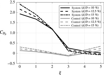
The pressure drag of the main cylinder with the addition of stationary control cylinders is greater than that of a bare cylinder, rising above 2 in some configurations as shown in figure 9. The presence of the control cylinders effectively increases the size of the main cylinder and increases the width of the wake. A similar increase was measured in the
 $Re_{D}=47\,000$
experiment. As the control cylinders are rotated at faster rates, the pressure drag on the system, including the main cylinder and rotating control cylinders, decreases monotonically for all of the configurations. The contribution of the control cylinders is small for low
 $\unicode[STIX]{x1D709}$
, but becomes a significant component of the total force for
 $\unicode[STIX]{x1D709}>3$
, which also corresponds to stable wakes. For
 $\unicode[STIX]{x1D709}>2$
, the total system drag is less than the drag on a bare cylinder without control cylinders, found to be
 $C_{D_{p}}=1.326$
with the present method. At high
 $\unicode[STIX]{x1D709}$
, the pressure drag on the system is less than zero for some of the cases, indicating the generation of thrust. Thrust generation by the rotation of the control cylinders is consistent with the numerical simulations of a pair of counter-rotating cylinders conducted by van Rees, Novati & Koumoutsakos (Reference van Rees, Novati and Koumoutsakos2015).
The pressure drag for the configurations with
 $g/D=0.05$
decreases with the rotation parameter,
 $\unicode[STIX]{x1D709}$
. The pressure drag of the system including the main cylinder and rotating control cylinders is indicated with ‘System’ and the contribution from the two control cylinders is indicated with ‘Control’ in the plot legend. Larger diameter control cylinders achieve a greater drag reduction than smaller control cylinders at the same rotation rate.

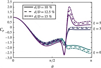
The pressure recovery from separation to reattachment points is greater for larger control cylinders at the same rotation rate.

The pressure profile along the main cylinder for the same set of configurations is also shown in figure 10. The pressure on the upstream side of the main cylinder (
 $\unicode[STIX]{x1D703}<\unicode[STIX]{x03C0}/2$
) is similar for all of the cases. In contrast, the pressure on the downstream side (
 $\unicode[STIX]{x1D703}>\unicode[STIX]{x03C0}/2$
) is increased by the rotating control cylinders, resulting in large drag reduction. Despite the similarity between the streamlines with those of a potential flow model shown in figure 6, pressure peaks on the downstream side reach values significantly greater than the upstream stagnation point, which is inconsistent with potential flow. Inviscid models are therefore anticipated to be incomplete in describing the increase of pressure on the downstream side of the main cylinder. Also of note is that the larger control cylinders increase the base pressure and reduce drag by a greater margin at the same rotation rate than smaller control cylinders.
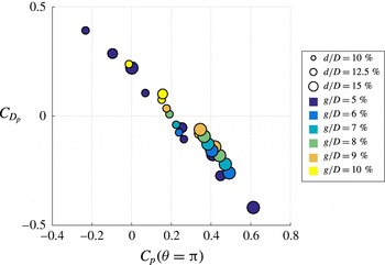
Increasing base pressure,
 $C_{p}(\unicode[STIX]{x1D703}=\unicode[STIX]{x03C0})$
, reduces the pressure drag,
 $C_{D_{p}}$
, which is a clear trend for all of the simulations. This trend is presented in figure 11, which summarizes the results for all of the cases with stable wakes.
The pressure drag is correlated with the base pressure coefficient.

6 Discussion
6.1 Mechanism of the pressure recovery
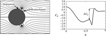
The controlled steady flows have a recirculating region around the control cylinder that is bounded by a dividing streamline that separates from and then reattaches to the main cylinder. This dividing streamline is shown in figure 12. Peaks in the pressure along the circumference of the main cylinder accompany the separation and reattachment points of the dividing streamline. Figure 12 also plots the pressure coefficient on the main cylinder for a controlled flow. The pressure at reattachment,
 $p_{r}$
, is greater than the pressure at separation,
 $p_{s}$
. This difference is the pressure recovery coefficient,
 $\unicode[STIX]{x0394}C_{p}=(p_{r}-p_{s})/(\unicode[STIX]{x1D70C}U_{\infty }^{2}/2)$
.
In the controlled steady flow, the pressure along the main cylinder presents two peaks associated with the separation and reattachment points of the dividing streamline. The rotating cylinder imparts energy to the fluid along the dividing streamline such that there is a pressure recovery,
 $\unicode[STIX]{x0394}C_{p}$
, from separation to reattachment.

The pressure and kinetic energy along a streamline are governed by the Bernoulli equation, which is applied to steady, incompressible, viscous flow without body forces in (6.1), as is described by Synolakis & Badeer (Reference Synolakis and Badeer1989). The velocity and pressure at two points along a streamline, denoted
 $\boldsymbol{u}_{1}$
,
 $\boldsymbol{u}_{2}$
and
 $p_{1}$
,
 $p_{2}$
, are related by the work done by the viscous force,
 $f_{vis}$
, along the streamline that connects them.
 $$\begin{eqnarray}\frac{1}{2}|\boldsymbol{u}_{1}|^{2}+{\displaystyle \frac{p_{1}}{\unicode[STIX]{x1D70C}}}=\int _{1}^{2}f_{vis}\,\text{d}s+\frac{1}{2}|\boldsymbol{u}_{2}|^{2}+{\displaystyle \frac{p_{2}}{\unicode[STIX]{x1D70C}}}.\end{eqnarray}$$
Substituting the separation and reattachment points highlighted in figure 12 into (6.1) shows that the pressure recovery is due to the viscous force along the streamline that connects them,
 $(p_{r}-p_{s})/\unicode[STIX]{x1D70C}=-\int _{s}^{r}f_{vis}\,\text{d}s$
.
The mechanical energy in the steady flow of an incompressible fluid is equal to the total pressure,
 $$\begin{eqnarray}E=\frac{1}{2}|\boldsymbol{u}|^{2}+{\displaystyle \frac{p}{\unicode[STIX]{x1D70C}}}.\end{eqnarray}$$
Differences in
 $E$
along a streamline thus reflect the work done by the viscous force along the streamline. An equation for
 $E$
can be obtained by taking the divergence of the Navier–Stokes equation
 $$\begin{eqnarray}\unicode[STIX]{x1D6FB}^{2}E=\unicode[STIX]{x1D74E}^{2}-\boldsymbol{u}\boldsymbol{\cdot }\unicode[STIX]{x1D6FB}\times \unicode[STIX]{x1D74E},\end{eqnarray}$$
where
 $\unicode[STIX]{x1D74E}$
is the vorticity. Equation (6.3) can be used to analyse instability by decomposing a flow into mean and disturbance components and identifying sources and sinks of mechanical energy of the disturbance flow (Sengupta, De & Sarkar Reference Sengupta, De and Sarkar2003a
; Sengupta et al.
Reference Sengupta, Kasliwal, De and Nair2003b
).
It is convenient to define
 $$\begin{eqnarray}B=E-E_{\infty },\end{eqnarray}$$
where
 $E_{\infty }=(U_{\infty }^{2}/2)+p_{\infty }/\unicode[STIX]{x1D70C}$
, so that
 $B=0$
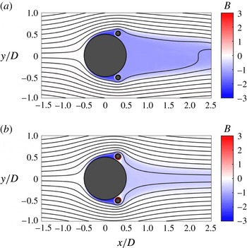
far upstream. Figure 13 shows
 $B$
for flows with
 $\unicode[STIX]{x1D709}=3$
and
 $\unicode[STIX]{x1D709}=5$
that are otherwise configured the same.
 $B$
is non-zero only within the cylinder’s boundary layer and wake, highlighting the regions of the flow where the viscous stress contributes to the mechanical energy balance. There is a local minimum in the boundary layer of the main cylinder upstream of the rotating control cylinders. As the separating boundary layer flow passes the rotating control cylinders,
 $B$
increases to a value that is close to uniform in the wake. In figure 13(b), the larger rotation parameter (
 $\unicode[STIX]{x1D709}=5$
) results in a greater recovery of pressure in the wake than the smaller rotation parameter in figure 13(a) (
 $\unicode[STIX]{x1D709}=3$
).
 $B$
, the total pressure or the sum of kinetic energy and pressure: (a)
 $\unicode[STIX]{x1D709}=3$
; (b)
 $\unicode[STIX]{x1D709}=5$
. The wake recovery of
 $B$
is greater for higher
 $\unicode[STIX]{x1D709}$
.

The net viscous stress field associated with the integral term in the mechanical energy balance of (6.1) is equal to the projection of the divergence of the viscous stress onto the local direction of the flow. The normalized net viscous stress field, denoted
 $S_{\unicode[STIX]{x1D708}}$
, for incompressible flow is
 $$\begin{eqnarray}S_{\unicode[STIX]{x1D708}}={\displaystyle \frac{(\boldsymbol{u}/U_{\infty })}{|\boldsymbol{u}/U_{\infty }|}}\boldsymbol{\cdot }\boldsymbol{f}_{vis}={\displaystyle \frac{(\boldsymbol{u}/U_{\infty })}{|\boldsymbol{u}/U_{\infty }|}}\boldsymbol{\cdot }\bigg({\displaystyle \frac{1}{Re_{D}}}\unicode[STIX]{x1D6FB}^{2}\bigg({\displaystyle \frac{\boldsymbol{u}}{U_{\infty }}}\bigg)\bigg).\end{eqnarray}$$
The power field associated with the viscous stress contribution to the mechanical energy balance of (6.1) is equal to the dot product of the net viscous stress with the velocity. The normalized viscous power field, denoted,
 $P_{\unicode[STIX]{x1D708}}$
, for incompressible flow is
 $$\begin{eqnarray}P_{\unicode[STIX]{x1D708}}=\bigg({\displaystyle \frac{\boldsymbol{u}}{U_{\infty }}}\bigg)\boldsymbol{\cdot }\bigg({\displaystyle \frac{1}{Re_{D}}}\unicode[STIX]{x1D6FB}^{2}\bigg({\displaystyle \frac{\boldsymbol{u}}{U_{\infty }}}\bigg)\bigg).\end{eqnarray}$$
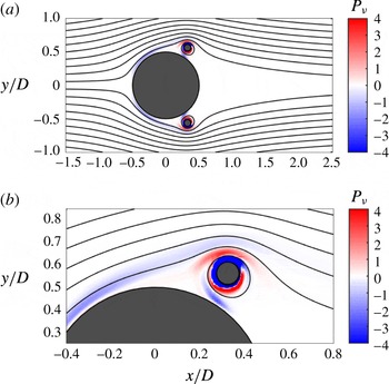
The
 $P_{\unicode[STIX]{x1D708}}$
field for a controlled steady flow is shown in figure 14. Negative power indicates decreasing
 $B$
along the streamline and positive power indicates increasing
 $B$
. Without an active flow control actuator,
 $P_{\unicode[STIX]{x1D708}}$
would be everywhere non-positive. With active control, the external forces required to maintain the rotation of the control cylinder drive regions of positive
 $P_{\unicode[STIX]{x1D708}}$
via the moving cylinder wall.
Net viscous shear power,
 $P_{\unicode[STIX]{x1D708}}$
, in the vicinity of the rotating control cylinder. The positive regions of
 $P_{\unicode[STIX]{x1D708}}$
, visible in the close view in (b), are driven by the external forces required to keep the control cylinder in steady rotation.

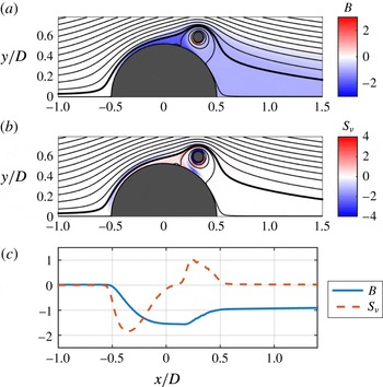
Figure 15(a,b) highlights a common streamline through the
 $B$
and
 $S_{\unicode[STIX]{x1D708}}$
fields. Figure 15(c) shows values of
 $B$
and
 $S_{\unicode[STIX]{x1D708}}$
along the highlighted streamline. Upstream of the main cylinder (
 $x/D<-0.5$
), both
 $B$
and
 $S_{\unicode[STIX]{x1D708}}$
are constant. This region is outside of the boundary layer and the mechanical energy balance is dominated by the inviscid and reversible exchange of kinetic energy and pressure. In the boundary layer of the main cylinder upstream of the rotating control cylinder (
 $-0.5<x/D<0.2$
), the negative
 $S_{\unicode[STIX]{x1D708}}$
reduces
 $B$
. As the streamline passes around the rotating control cylinder (
 $0.2<x/D<0.5$
), the net viscous stress changes sign to positive as it passes through the region of positive
 $S_{\unicode[STIX]{x1D708}}$
created by the control cylinder. As a result,
 $B$
increases, recovering some of the energy lost in the boundary layer of the main cylinder. Finally, as the streamline enters the wake (
 $x/D>0.5$
),
 $B$
and
 $S_{\unicode[STIX]{x1D708}}$
are constant as the streamline returns to a region dominated by an inviscid mechanical energy balance.
A common streamline is highlighted through the
 $B$
(a) and
 $S_{\unicode[STIX]{x1D708}}$
(b) fields. The values of
 $B$
and
 $S_{\unicode[STIX]{x1D708}}$
along the highlighted streamline (c) show that
 $B$
recovers due to positive
 $S_{\unicode[STIX]{x1D708}}$
near the rotating control cylinder.

6.2 Pressure recovery scaling
The steady flow around the control cylinder is described by four dimensionless numbers
 $$\begin{eqnarray}\displaystyle & \displaystyle Re_{d}={\displaystyle \frac{\unicode[STIX]{x1D70C}U_{\infty }d}{\unicode[STIX]{x1D707}}} & \displaystyle\end{eqnarray}$$
 $$\begin{eqnarray}\displaystyle & \displaystyle \unicode[STIX]{x0394}C_{p}={\displaystyle \frac{(p_{r}-p_{s})}{\frac{1}{2}\unicode[STIX]{x1D70C}U_{\infty }^{2}}} & \displaystyle\end{eqnarray}$$
 $$\begin{eqnarray}\displaystyle & \displaystyle \unicode[STIX]{x1D709}={\displaystyle \frac{u_{surf}}{U_{\infty }}} & \displaystyle\end{eqnarray}$$
 $$\begin{eqnarray}\displaystyle & \displaystyle d^{\ast }={\displaystyle \frac{d}{g}} & \displaystyle\end{eqnarray}$$
including a Reynolds number, pressure recovery coefficient, rotation parameter, and normalized diameter. The main cylinder diameter is neglected from these numbers because it is much larger than the control cylinder diameter and gap width. There are two remaining length scales, the control cylinder diameter,
 $d$
, and gap to main cylinder,
 $g$
.
Active flow control actuator performance is often highly correlated with the actuator momentum flux (Cattafesta & Sheplak Reference Cattafesta and Sheplak2011). In the case of rotating circular cylinders in cross-flow, there are two candidate momentum fluxes that could be used to predict the pressure recovery, an inviscid scaling and a viscous scaling.
The inviscid scaling is the momentum flux associated with the lift force of a rotating cylinder in a cross-flow. This flux is called ‘inviscid’ because a lift force is present even in inviscid flows, as long as there is bound circulation. The lift force of the rotating control cylinder can be modelled as the lift of a point vortex with the same circulation. Using this model, the inviscid scaling is expressed as
 $$\begin{eqnarray}\unicode[STIX]{x0394}C_{p}\propto {\displaystyle \frac{\unicode[STIX]{x1D70C}U_{\infty }u_{surf}d}{\frac{1}{2}\unicode[STIX]{x1D70C}U_{\infty }^{2}D}}\propto \unicode[STIX]{x1D709}d^{\ast }.\end{eqnarray}$$
While it is well known that inviscid models based on the circulation at the cylinder boundary overestimate the lift, Kang, Choi & Lee (Reference Kang, Choi and Lee1999) show that the mean lift increases almost linearly with rotation rate. Therefore, we expect the linear relationship in this inviscid scaling to be accurate.
The viscous scaling is the momentum flux associated with the boundary layer of the rotating control cylinder. The viscous diffusion of momentum from the rotating cylinder wall can be modelled simply as the laminar boundary layer over a flat plate with length,
 $\unicode[STIX]{x03C0}d$
, and velocity,
 $u_{surf}$
. The laminar boundary layer thickness scales with
 $\unicode[STIX]{x03C0}d{Re_{d}}^{-1/2}$
, and its momentum flux is proportional to
 $\unicode[STIX]{x1D70C}u_{surf}^{2}d{Re_{d}}^{-1/2}/2$
. Normalizing this by the free-stream momentum flux results in a viscous scaling model for the pressure recovery.
 $$\begin{eqnarray}\unicode[STIX]{x0394}C_{p}\propto {\displaystyle \frac{\frac{1}{2}\unicode[STIX]{x1D70C}u_{surf}^{2}dRe_{d}^{-1/2}}{\frac{1}{2}\unicode[STIX]{x1D70C}U_{\infty }^{2}D}}\propto \unicode[STIX]{x1D709}^{2}d^{\ast }Re_{d}^{-1/2}.\end{eqnarray}$$
Recasting (6.12) in terms of the Reynolds number based on the main cylinder diameter,
 $Re_{D}$
, pulls all parameters associated with the control cylinders (
 $d^{\ast }$
and
 $\unicode[STIX]{x1D709}$
) out of the Reynolds number:
 $$\begin{eqnarray}\unicode[STIX]{x0394}C_{p}\propto \unicode[STIX]{x1D709}^{3/2}{d^{\ast }}^{1/2}Re_{D}^{-1/2}.\end{eqnarray}$$
The viscous scaling in (6.13) represents the skin friction and so the torque required to rotate the cylinder. The inviscid scaling in (6.11), on the other hand, is associated with the lift force.
The boundary layer profiles for a rotating cylinder and flow over a flat plate are different, but the skin friction scales in the same way with respect to an appropriate length and velocity for each. These are the diameter and surface speed for the rotating cylinder and the plate length and free-stream velocity for flow over a flat plate. Hoerner & Borst (Reference Hoerner and Borst1985) use this equivalent scaling to present an estimate of the torque of a rotating cylinder using a flat-plate skin friction coefficient.
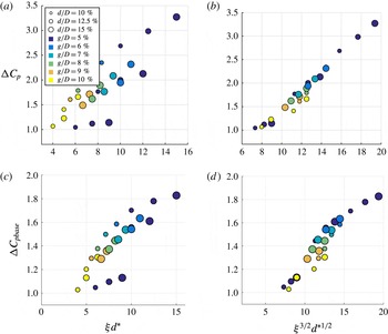
The results of the numerical simulations are plotted against both the inviscid scaling from (6.11) and the viscous scaling from (6.13) in figure 16(a,b). The
 $Re_{D}$
term is neglected from the viscous scaling in figure 16(b,d) because all simulations were run at
 $Re_{D}=500$
. The pressure recovery,
 $\unicode[STIX]{x0394}C_{p}$
, collapses with respect to the viscous scaling for this set of configurations, indicating that the mechanism of pressure recovery is fundamentally viscous. Figure 16(c,d) shows the results for the pressure recovery from separation to the base of the main cylinder,
 $\unicode[STIX]{x0394}C_{p_{base}}=(p_{\unicode[STIX]{x1D703}=\unicode[STIX]{x03C0}}-p_{s})/(\unicode[STIX]{x1D70C}U_{\infty }^{2}/2)$
. The trends for
 $\unicode[STIX]{x0394}C_{p_{base}}$
are similar to those for
 $\unicode[STIX]{x0394}C_{p}$
, but with diminishing returns for higher control effort. The diminishing returns are associated with the viscous loss of mechanical energy between reattachment and the base of the main cylinder at
 $\unicode[STIX]{x1D703}=\unicode[STIX]{x03C0}$
, which is apparent in the pressure profiles for the
 $\unicode[STIX]{x1D709}=5$
flows in figure 10. Despite the additional viscous loss of pressure between reattachment and the base of the main cylinder, the viscous scaling better describes the mechanism of base pressure recovery and pressure drag reduction than the inviscid scaling.
The pressure recovery from separation to reattachment of the dividing streamline (a,b) and from separation to the base of the cylinder at
 $\unicode[STIX]{x1D703}=\unicode[STIX]{x03C0}$
(c,d), plotted with respect to the inviscid momentum flux scaling,
 $\unicode[STIX]{x1D709}d^{\ast }$
(a,c) and the viscous momentum flux scaling,
 $\unicode[STIX]{x1D709}^{3/2}{d^{\ast }}^{1/2}$
(b,d). The viscous scaling (b,d) more accurately describes the pressure recovery mechanism.

A control cylinder can interact with a larger flow through a displacement effect, a circulation effect (6.11), and a viscous effect (6.13). Strykowski & Sreenivasan (Reference Strykowski and Sreenivasan1990) demonstrate a displacement effect of a static control cylinder on the wake of a larger upstream cylinder. Lim, Sengupta & Chattopadhyay (Reference Lim, Sengupta and Chattopadhyay2004) report experimental visualizations of the influence of a displacement and also of a circulation effect of a rotating cylinder on a laminar flat-plate boundary layer. In those experiments, the rotating cylinder was positioned well outside of the flat-plate boundary layer so the vorticity fields from each did not interact strongly. Control cylinders were placed in close proximity to the main cylinder in numerical simulations by Mittal (Reference Mittal2001), but the diameter was constant and so circulation and viscous effects could not be easily distinguished. The present configuration locates the control cylinder close to the main cylinder such that the vorticity fields of the two interact strongly, as can be seen in figure 7. Also, the diameter of the control cylinder is varied so that circulation effects can be distinguished from viscous effects. The result is a new viscous scaling law, shown in comparison with the inviscid scaling or circulation effect in figure 16.
6.3 Power consumption of control with rotating cylinders
The power consumption of active flow control actuators is an important performance metric, particularly in applications in which the goal of flow control is to reduce the total power consumption of a system, such as a self-propelled vehicle. The rotational power consumption coefficient,
 $C_{pow}^{rot}$
, is equal to the sum of the power consumed by the two rotating cylinders that are driven with a torque,
 $T$
, at angular velocity,
 $\unicode[STIX]{x1D6FA}$
, normalized by the free-stream flux of kinetic energy through the projected area of the main cylinder:
 $$\begin{eqnarray}C_{pow}^{rot}={\displaystyle \frac{2T\unicode[STIX]{x1D6FA}}{\frac{1}{2}\unicode[STIX]{x1D70C}U_{\infty }^{3}D}}.\end{eqnarray}$$
The power consumption,
 $C_{pow}^{rot}$
, for the numerical simulations is found by integrating the viscous shear stress as discussed in § 4. In the water tunnel experiment, drive-train friction far exceeded the hydrodynamic viscous stress on the rotating cylinders. This makes the signal to noise ratio of measurements of the power consumption coefficient via the driving electric motor power consumption unsatisfactorily high. Instead, the power consumption is estimated using the torque coefficient of a rotating cylinder in a free stream with
 $Re=1000$
and
 $\unicode[STIX]{x1D709}=3$
found numerically by Padrino & Joseph (Reference Padrino and Joseph2006). This result is conservative because it is computed for a flow with
 $Re=1000$
, which is less than the experimental Reynolds number,
 $Re_{d}=5875$
.
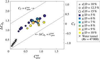
The reduction in pressure drag coefficient from that of a circular cylinder without control cylinders,
 $\unicode[STIX]{x0394}C_{D_{p}}$
, and the thrust coefficient,
 $C_{T}=-C_{D_{p}}$
, are plotted with respect to
 $C_{pow}^{rot}$
in figure 17. The active flow control is efficient when the reduction in power required to tow a bare cylinder is greater than the power consumption, indicated by
 $\unicode[STIX]{x0394}C_{D_{p}}>C_{pow}^{rot}$
. The configurations investigated numerically with stable wakes, as well as the water tunnel experimental configurations, shown in figure 17, are all efficient because they lie above the
 $\unicode[STIX]{x0394}C_{D_{p}}=C_{pow}^{rot}$
line. The maximum possible drag reduction for a given power input is indicated by the
 $C_{T}=C_{pow}^{rot}$
line. This physical limit represents all power consumed creating thrust on the main cylinder with no losses. Configurations with larger gaps consume more power than those with small gaps, so the most efficient configurations are those with small gaps.
The pressure drag reduction,
 $\unicode[STIX]{x0394}C_{D_{p}}$
, increases with diminishing returns with respect to
 $C_{pow}^{rot}$
. The most efficient configurations in this study are those with the smallest gaps between the main and rotating control cylinders. At
 $Re_{D}=500$
, all of the configurations are beneficial (
 $\unicode[STIX]{x0394}C_{D_{p}}>C_{pow}^{rot}$
). The
 $C_{T}=C_{pow}^{rot}$
line indicates the maximum physically possible drag reduction.

7 Conclusion
Control of the streaming flow past a circular cylinder with rotating control cylinders was implemented in a water tunnel at
 $Re_{D}=47\,000$
with a three-dimensional and turbulent wake. PIV measurements show that the rotating cylinders narrow the mean wake and shorten the length of the recirculation region. When the cylinders were rotated with
 $\unicode[STIX]{x1D709}=3.4$
, the highest tested, the drag reduced by
 $45\,\%$
. A series of two-dimensional numerical simulations at
 $Re_{D}=500$
investigated different configurations of control cylinder rotation rate,
 $\unicode[STIX]{x1D709}$
, diameter,
 $d$
, and gap to main cylinder,
 $g$
. In a subset of the tested configurations, the rotating cylinders completely stabilize the wake.
A salient feature of the stabilized flow is a recirculation region around the control cylinder. The moving wall of the rotating cylinder drives a region of positive viscous power,
 $P_{\unicode[STIX]{x1D708}}$
, that energizes the dividing streamline, enabling it to reattach to the main cylinder. The streamline reattaches to the main cylinder with greater pressure than at separation, resulting in increased base pressure and reduced pressure drag.
The pressure recovery in the
 $Re_{D}=500$
numerical simulations scales with the momentum flux of the control cylinder associated with viscous effects in its boundary layer as opposed to the lift force. This is counter to the intuition that the circulation and lift force, which are present in inviscid flow, accurately describe the pressure recovery mechanism. This new viscous scaling could inform the design and development of rotating cylinder and other implementations of moving boundary flow control.
The power consumption of the rotating cylinders is computed in the
 $Re_{D}=500$
simulations and shown to be greater in configurations with large gaps between the main and rotating control cylinders. As a result, of the configurations simulated, those with the smallest gaps are the most efficient. All configurations, including both those in the
 $Re_{D}=500$
numerical simulations and the
 $Re_{D}=47\,000$
water tunnel experiments, are beneficial because they effect a reduction in the drag coefficient that is greater than the power consumption,
 $\unicode[STIX]{x0394}C_{D_{p}}>C_{pow}^{rot}$
.
Future work should investigate the Reynolds number dependence of the control mechanism. In both the
 $Re_{D}=500$
numerical simulations and the
 $Re_{D}=47\,000$
water tunnel experiments, the boundary layers are expected to be laminar. At higher Reynolds numbers the boundary layers will transition to turbulence, which will influence both the efficacy and efficiency of flow control with rotating cylinders.
Acknowledgements
The authors acknowledge support from the Singapore-MIT Alliance for Research and Technology, and the MIT Sea Grant Program.