

1 Introduction
The subject of this paper is the accurate calculation of steady-state free-surface flows where a disturbance has caused the emergence of distinct groups of gravity and capillary waves. In particular, we will discuss flow regimes that exist in the low-speed limit and numerically confirm the existence of a new class of waves predicted by Trinh & Chapman (Reference Trinh and Chapman2013b).
The canonical application of free-surface flow is the fishing-line problem first reported by Russell (Reference Russell1845). Figure 1 corresponds to Russell’s original illustration of a two-dimensional cross-section of the free surface for uniform flow past a fishing line. Inspired by Russell’s report, Rayleigh (Reference Rayleigh1883) modelled the fishing line as a point pressure force and demonstrated that waves of constant amplitude exist when the flow is above a certain speed (approximately  $23~\text{cm}~\text{s}^{-1}$ in water of infinite depth). The disturbances upstream of the fishing line are capillary waves, principally governed by surface tension, while those downstream are due to gravity (see also § 271 of Lamb (Reference Lamb1932)).
Then, in the latter half of the twentieth century, it became possible to compute numerical solutions of the full nonlinear potential-flow equations for steady-state problems involving different geometries. As it pertains to the gravity-only problem, we mention as examples the works of Vanden-Broeck & Tuck (Reference Vanden-Broeck and Tuck1977), King & Bloor (Reference King and Bloor1987, Reference King and Bloor1990) and Forbes & Schwartz (Reference Forbes and Schwartz1982), although interest continues well into recent years in, for example, Părău & Vanden-Broeck (Reference Părău and Vanden-Broeck2002), Binder & Vanden-Broeck (Reference Binder and Vanden-Broeck2007) and Binder, Blyth & McCue (Reference Binder, Blyth and McCue2013). For reasons that will become clear, the numerical study of the types of steady-state gravity–capillary profiles illustrated in figure 1 is a much more difficult problem.
Original illustration from plate 57 of Russell (Reference Russell1845) depicting the short-wavelength capillary ripples upstream and long-wavelength gravity waves downstream of a fishing line. Note that, in Russell’s illustration, viscous effects are included.

Like the methodology developed in Rayleigh (Reference Rayleigh1883), theoretical analysis of such wave–structure free-surface problems usually begins by linearising the governing equations about a small parameter, say  $\unicode[STIX]{x1D6FF}$, related to the size of the obstruction (linear geometrical theory). In addition to
 $\unicode[STIX]{x1D6FF}$, gravity–capillary flows are typically characterised by two non-dimensional parameters: the Froude number,
 $F$, and the inverse Bond number,
 $T$, defined by
 $$\begin{eqnarray}F=\frac{U}{\sqrt{gL}}\quad \text{and}\quad T=\frac{\unicode[STIX]{x1D70E}}{\unicode[STIX]{x1D70C}gL^{2}}.\end{eqnarray}$$
Here,  $U$ and
 $L$ are the chosen velocity and length scales,
 $\unicode[STIX]{x1D70C}$ is density and
 $\unicode[STIX]{x1D70E}$ is the surface tension parameter. As is convention in water-wave studies, we refer to
 $T$ directly as the Bond number. In this work, we focus on subcritical flows, i.e. those with
 $F<1$.
As explained by Forbes (Reference Forbes1983), linear geometrical theory indicates that for  $\unicode[STIX]{x1D6FF}\ll 1$ there exists a critical curve,
 $T=T_{G}(F)$, that divides the subcritical part of the
 $(F,T)$ plane into two regions. Solutions with
 $T<T_{G}(F)$ are called Type I and are associated with the constant-amplitude waves of figure 1, while solutions with
 $T>T_{G}(F)$ are called Type II and consist of localised solitary waves.
Recently, it was predicted in Trinh & Chapman (Reference Trinh and Chapman2013a,Reference Trinh and Chapmanb) that several new classes of solution can occur for nonlinear geometries with  $\unicode[STIX]{x1D6FF}=O(1)$, in the limit of small Froude and Bond numbers,
 $F,T\rightarrow 0$. The authors considered the case of a right-angled step and used techniques from exponential asymptotics to show that the typical Rayleigh (Reference Rayleigh1883) bifurcation curve predicted for linear geometry widens into a band as the height of the step increases, and that, within this band, a range of new solutions can be found. This work aims to numerically confirm these new, Type III waves, and thus we seek to develop methods that allow us to accurately solve the governing equations for nonlinear geometries. In doing so we make use of ideas developed in Trinh (Reference Trinh2016, Reference Trinh2017), where computationally problematic integral terms (cf. (4.8)) are removed from the governing equations through a systematic asymptotic reduction in the low-speed,
 $F,T\rightarrow 0$ limit.
1.1 The radiation problem
Numerical solutions of steady-state free-surface problems require the use of effective radiation conditions – that no energy may come from infinity – on the edges of a truncated computational domain. However, it is often unclear exactly how one can impose such a condition in practice, particularly when capillary waves are present. Stoker (Reference Stoker1957) had previously provided several remarks on this unexpectedly challenging aspect of determining steady-state flows. As he writes (p. 175):
…it is by no means clear a priori what conditions should be imposed at infinity in order to ensure the uniqueness of a simple harmonic solution […] the steady state problem is unnatural – in the author’s view, at least – because a hypothesis is made about the motion that holds for all time, while Newtonian mechanics is basically concerned with the prediction – in a unique way, furthermore – of the motion of a mechanical system from given initial conditions.
As Stoker notes, one should in principle formulate and solve an initial-value problem where it is often sufficient to impose only boundedness of the solution at infinity. Afterwards, the time-dependent solution may then be evolved to a steady state. In practice, however, there are a myriad reasons why solving a steady-state formulation may be necessary – beyond simple computational efficiency. For instance, the study of solutions of the direct steady-state model may yield a wealth of information about the physical or mathematical structure of the problem, information that cannot be easily obtained through time-dependent experiments.
Apart from specialised configurations (e.g. localised solitary waves), there has not yet been a proposed solution of the radiation problem, particularly for the case of Type I solutions. One approach, suggested by Grandison & Vanden-Broeck (Reference Grandison and Vanden-Broeck2006), approximates the solution outside of the main computational domain using a Fourier series whose coefficients are found as part of the solution. Although this method was able to successfully compute a number of Type I solutions for flow over a small circular cylinder (non-dimensional radius  $\unicode[STIX]{x1D6FF}=0.05$), we have found that convergence is difficult to obtain for nonlinear geometries. Other options for correctly enforcing the radiation condition include the addition of artificial viscosity, say
 $\unicode[STIX]{x1D707}$ (as in Părău, Vanden-Broeck & Cooker (Reference Părău, Vanden-Broeck and Cooker2007)) or by solving the full time-dependent problem (as in Părău, Vanden-Broeck & Cooker (Reference Părău, Vanden-Broeck and Cooker2010) and Moreira & Peregrine (Reference Moreira and Peregrine2010)). However, in both cases, it is not clear that taking the limit
 $\unicode[STIX]{x1D707}\rightarrow 0$ or
 $t\rightarrow \infty$ will allow recovery of the full set of solutions when
 $\unicode[STIX]{x1D707}=0$ and
 $t=\infty$.
Our main strategy forwards is to explain how, in the limit  $F,T\rightarrow 0$, the governing equations may be reduced to a single second-order differential equation, for which it is clear how the radiation condition should be applied. We solve this reduced model as a boundary-value problem, and use it to verify the new waves predicted in Trinh & Chapman (Reference Trinh and Chapman2013b). The reduced model is derived in §§ 4 and 5, and then solved numerically in § 6. But first, §§ 2 and 3 give a simple explanation for one of the new classes of waves.
2 An explanation of the new waves via the dispersion relations
Here, we give a simple explanation of one of the new classes of gravity–capillary waves that were previously described using the more sophisticated exponential asymptotics. This is done by comparing upstream and downstream dispersion relations, and is similar in spirit to arguments in Binder & Vanden-Broeck (Reference Binder and Vanden-Broeck2007).
2.1 The upstream dispersion relation
The dispersion relation that governs linear perturbations of wavenumber  $\tilde{k}$ from uniform flow of speed
 $U$ and depth
 $h$ is (cf. (2.90) in Vanden-Broeck (Reference Vanden-Broeck2010))
 $$\begin{eqnarray}U^{2}=\left[\frac{g}{\tilde{k}}+\frac{\unicode[STIX]{x1D70E}}{\unicode[STIX]{x1D70C}}\tilde{k}\right]\tanh (\tilde{k}h).\end{eqnarray}$$
In most typical formulations, the dispersion relation is defined in the context of the upstream quantities; thus rescaling the expression above, we have
 $$\begin{eqnarray}F^{2}=\left[\frac{1}{k}+Tk\right]\tanh (k)\equiv G(k;T).\end{eqnarray}$$
In (2.2), we have used the mean upstream channel height,  $L=h_{up}$, and velocity,
 $U=U_{up}$, for the definitions of the Froude and Bond numbers (cf. (1.1)). The wavenumber has been non-dimensionalised via
 $$\begin{eqnarray}k=\tilde{k}h_{up}.\end{eqnarray}$$
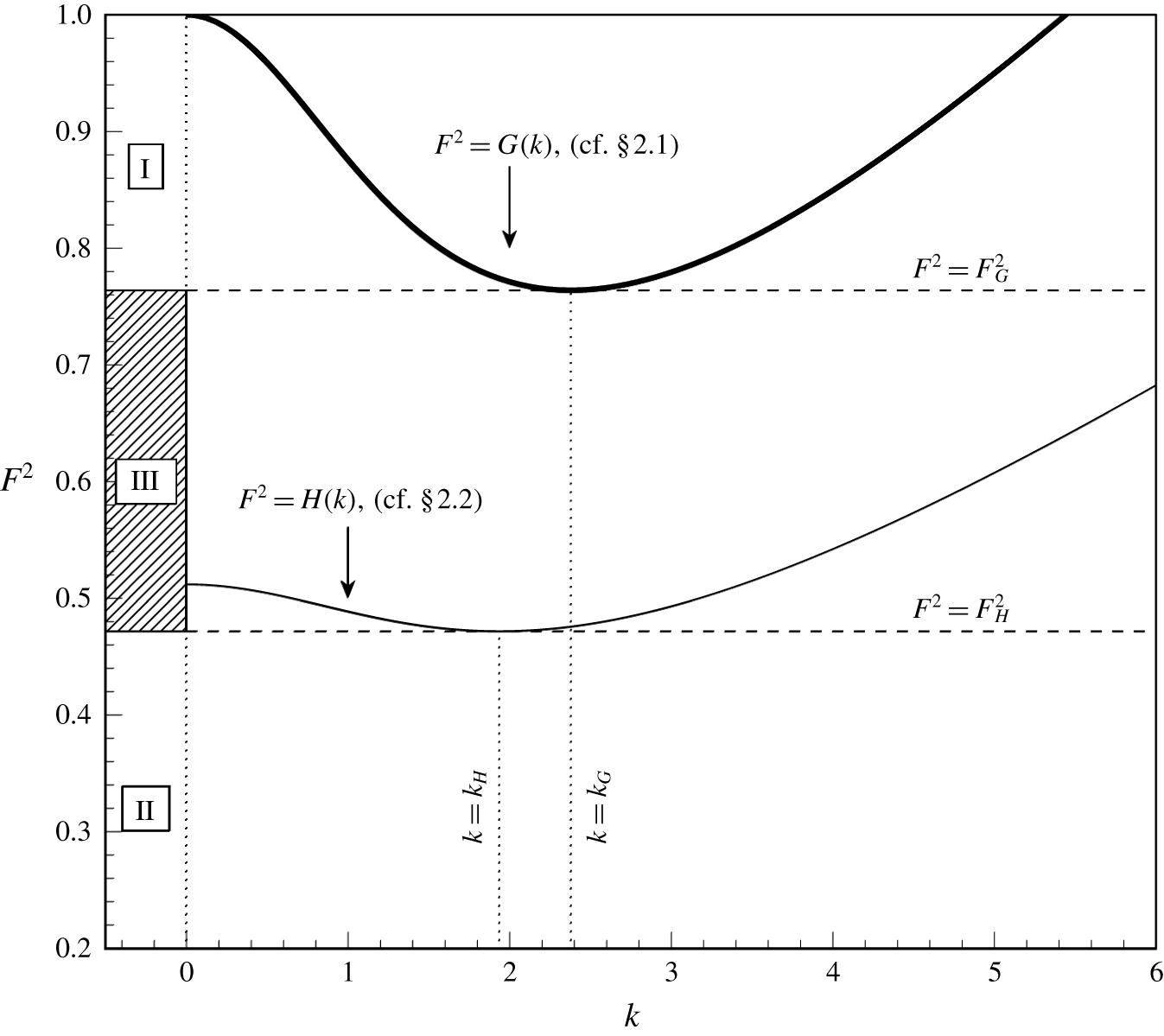
Thus, for a given value of  $T$, the dispersion relation
 $F^{2}=G(k)$ can be plotted in the
 $(k,F^{2})$ plane. An example profile of
 $G(k)$, with
 $T=0.15$, is shown in figure 2.
Upstream (thick) and downstream (thin) dispersion relations. The upstream relation  $G(k)$ is given by (2.2), and the downstream dispersion relation
 $H(k)$ is given by (2.6). Both are plotted with
 $T=0.15$, and the depth ratio in
 $H(k)$ is
 $h_{d/u}=0.8$. Constant-amplitude waves exist for values of
 $F$ that intersect the dispersion curve. Thus there is a region, marked ‘III’, where constant-amplitude waves only exist downstream.

Note that, if  $T<1/3$, the upstream dispersion relation
 $G(k)$ has a minimum at
 $(k_{G},F_{G}^{2})$. The existence of the local minimum leads to two possible types of solutions within subcritical flows (
 $F<1$):
- Type I.
If the Froude number lies within the band
 $F_{G}<F<1$, labelled I in figure 2, then there exist two distinct real wavenumbers. The smaller of the two wavenumbers corresponds to gravity waves and the larger to capillary waves. The solution consists of constant-amplitude capillary waves upstream and constant-amplitude gravity waves downstream.
- Type II.
If, however, the Froude number is less than the minimum of
$G(k)$ and in regions II and III of figure 2, i.e. $0<F<F_{G}$, then solutions to (2.2) are complex-valued. Thus the wavetrains decay in the far field.


2.2 The downstream dispersion relation
In addition to the two classes described above, the analysis of Trinh & Chapman (Reference Trinh and Chapman2013b) uses techniques from exponential asymptotics to predict several new classes of waves that occur in the low-Froude-number, low-Bond-number limit for finite-bodied (nonlinear) objects. However, there is a simple explanation for one of these new classes. The key idea is that, if the size of the step is sufficiently large, then the velocity and length scales downstream of the step must be redefined. Consequently, a different dispersion relation applies downstream.
We introduce the height and velocity ratios,
 $$\begin{eqnarray}h_{d/u}=\frac{h_{down}}{h_{up}}\quad \text{and}\quad U_{d/u}=\frac{U_{down}}{U_{up}},\end{eqnarray}$$
and the downstream Froude and Bond numbers, as well as downstream wavenumber,
 $$\begin{eqnarray}F=F_{down}\frac{\sqrt{h_{d/u}}}{U_{d/u}},\quad T=T_{down}h_{d/u}^{2},\quad k=\frac{k_{down}}{h_{d/u}},\end{eqnarray}$$
where by mass conservation  $h_{d/u}=1/U_{d/u}$.
Applying (2.1) to these downstream quantities, and rewriting in terms of upstream quantities, we must have
 $$\begin{eqnarray}F^{2}=h_{d/u}^{2}\left[\frac{1}{k}+Tk\right]\tanh (h_{d/u}k)\equiv H(k;T,h_{d/u}).\end{eqnarray}$$
Thus, in addition to the upstream dispersion relation  $G(k)$, we plot the downstream dispersion relation
 $H(k)$ on figure 2, for the same value of
 $T$ and with
 $h_{d/u}=0.8$. The downstream dispersion curve
 $H(k)$ has a local minimum at
 $(k_{H},F_{H}^{2})$. Consequently, if the upstream Froude number is selected from within the band
 $F_{H}<F<F_{G}$, then, although the upstream dispersion relation predicts decaying waves, the downstream dispersion relation indicates the presence of constant-amplitude waves. The result is a third class of solutions, in addition to those described in § 2.1.
- Type III.
Decaying waves upstream and constant-amplitude gravity waves downstream. This regime is labelled as III in figure 2.
2.3 A study of the $(F,T)$ plane

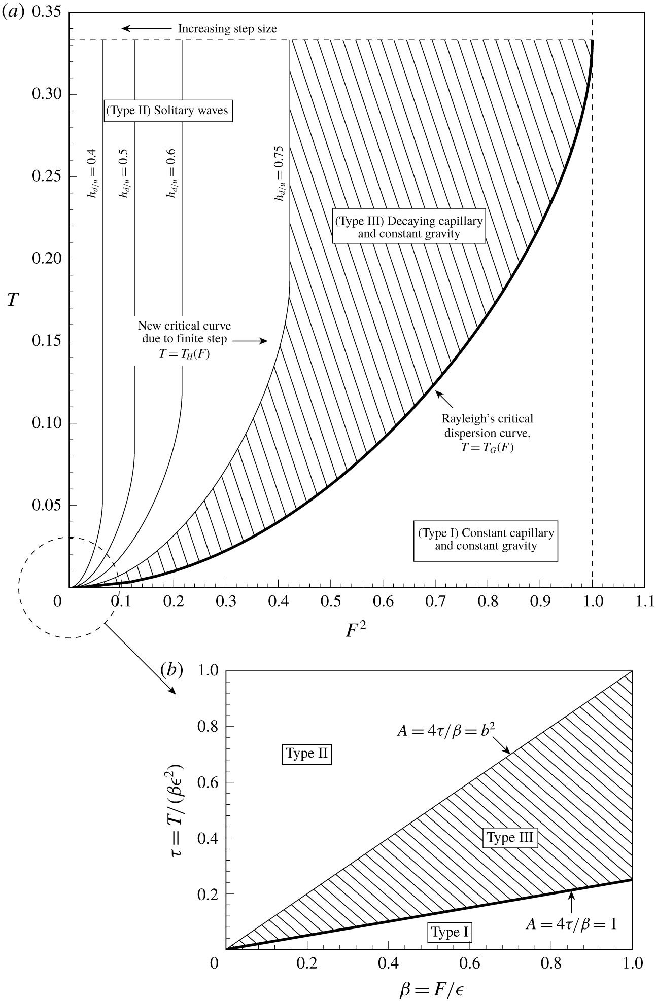
The bifurcation between constant-amplitude waves and decaying waves can also be viewed in the  $(F,T)$ plane, and this is shown in figure 3(a). There are two important features.
Firstly, notice the thick line in figure 3(a). This is essentially Rayleigh’s critical dispersion curve discussed in §§ 1 and 2.1. That is, for  $F<1$ and
 $T<1/3$, there exists a critical curve
 $T=T_{G}(F)$, which corresponds to the minimum over
 $k$ of the upstream dispersion relation
 $G(k;T)$ for each
 $T$, where
 $G(k)$ is given in (2.2). For linear geometries, this is the only critical curve. Configurations below the curve have constant-amplitude waves (Type I solutions), and configurations above the curve have decaying waves (Type II solutions).
Secondly, notice the sequence of thinner curves in figure 3(a). For the nonlinear step, a second critical curve  $T=T_{H}(F)$ exists, which corresponds to minima in the downstream dispersion relation
 $H(k;T)$, given by (2.6). New solutions (Type III) with decaying capillary waves and constant-amplitude gravity waves are located in the region of the
 $(F,T)$ plane that lies between these two curves. Note that the area of this region increases with the size of the step. The thin lines in figure 3 show the downstream critical curve
 $T_{H}(F)$ for various values of the depth ratio
 $h_{d/u}$, with the shaded area giving the region where new waves can be found for the particular case of
 $h_{d/u}=0.75$.
(a) Upstream (thick) and downstream (thin) bifurcation curves in the  $(F,T)$ plane, as discussed in § 2.3. For the case of
 $h_{d/u}=0.75$, the shaded area between them gives the region where new waves are possible. As
 $h_{d/u}$ decreases, the step size becomes larger and the area between the two bifurcation curves grows. (b) The different regions in the low-speed limit, where the boundaries of the bifurcation curve are described in terms of the step-height parameter
 $b$ (cf. § 3).

3 Asymptotics in the limit of small Froude and Bond numbers
Although our study of linear dispersion relations in the previous sections has given an insight into the new regimes in the  $(F,T)$ plane, it is important to recall that (2.2) and (2.6) are derived from the study of the free-surface problem assuming a flat-bottomed channel, which is only valid sufficiently far upstream and downstream. To derive a spatially dependent dispersion relation that connects the upstream and downstream regions, it is necessary to use the more complex exponential asymptotics, which are valid as
 $F,T\rightarrow 0$. Since it is in this low-speed limit where the new waves are predicted, we rewrite the dispersion relation (2.1) with
 $$\begin{eqnarray}F^{2}=\unicode[STIX]{x1D6FD}\unicode[STIX]{x1D716}\quad \text{and}\quad T=\unicode[STIX]{x1D6FD}\unicode[STIX]{x1D70F}\unicode[STIX]{x1D716}^{2},\end{eqnarray}$$
for  $\unicode[STIX]{x1D716}\ll 1$, following scalings from previous works (Trinh & Chapman Reference Trinh and Chapman2013a,Reference Trinh and Chapmanb).
In the limit  $\unicode[STIX]{x1D716}\rightarrow 0$, the wavenumber scales like
 $k=\hat{k}/\unicode[STIX]{x1D716}$. It will be shown below in § 4 that, to leading order in
 $\unicode[STIX]{x1D716}$, the asymptotic values of the speed downstream and upstream are
 $\sqrt{b}$ and unity, respectively, where
 $b$ is a parameter describing the step height. The velocity scale ratio for flow over a step is therefore
 $$\begin{eqnarray}U_{d/u}=\sqrt{b}+O(\unicode[STIX]{x1D716})\sim \frac{1}{h_{d/u}}.\end{eqnarray}$$
In this low-speed regime,  $\tanh (k)\rightarrow 1$ and the dispersion relation (2.2) becomes
 $$\begin{eqnarray}\unicode[STIX]{x1D6FD}\unicode[STIX]{x1D70F}\unicode[STIX]{x1D716}^{2}k^{2}-\unicode[STIX]{x1D6FD}\unicode[STIX]{x1D716}k+1=0\end{eqnarray}$$
with solutions
 $$\begin{eqnarray}k_{up}=\frac{1\pm \sqrt{1-A}}{2\unicode[STIX]{x1D70F}\unicode[STIX]{x1D716}},\end{eqnarray}$$
where  $A=4\unicode[STIX]{x1D70F}/\unicode[STIX]{x1D6FD}$. This is the typical small-step wavenumber in the limit of small Froude and Bond numbers, and predicts a band
 $A\in [0,1]$ where wavenumbers are real.
However, for a large step we must use (2.6) and then (2.5) to calculate the downstream wavenumbers as
 $$\begin{eqnarray}k_{down}=k_{up}h_{d/u}=\frac{b\pm \sqrt{b^{2}-A}}{2\unicode[STIX]{x1D70F}\sqrt{b}\unicode[STIX]{x1D716}}.\end{eqnarray}$$
Thus, if the Froude and Bond numbers are chosen so that  $A\in [1,b^{2}]$, then an additional regime is predicted, before the localised solitary waves emerge for
 $A>b^{2}$. The three different regions are illustrated in figure 3(b). The function
 $\unicode[STIX]{x1D712}(\unicode[STIX]{x1D719})$ that gives the spatially varying phase of the waves is found in § 3 of Trinh & Chapman (Reference Trinh and Chapman2013b). Comparison of (3.9) in that work with the expressions above shows that the wavenumbers here are just the far-field limits of
 $\unicode[STIX]{x1D712}$, as
 $|\unicode[STIX]{x1D719}|\rightarrow \infty$.
In both (3.4) and (3.5), the plus root becomes singular as  $\unicode[STIX]{x1D70F}\rightarrow 0$. This root therefore corresponds to capillary waves, and the minus root must correspond to gravity waves. This removes any ambiguity introduced by the extra dispersion relation, as we have exactly one upstream wavenumber that satisfies the radiation condition. The wavenumbers
 $k_{up}$ and
 $k_{down}$ can thus be used to verify that numerical solutions satisfy the radiation condition. However, these wavenumbers can also be used to prescribe the behaviour of the flow at infinity, and indeed this approach will later allow us to numerically confirm the existence of the new waves in the reduced model. First, we expand on the discussion of § 1.1, and illustrate the issues surrounding the numerical solution of the full problem.
4 Boundary-integral formulation
Consider steady, two-dimensional potential flow of an incompressible fluid in a channel with upstream velocity  $U$, and a prescribed length scale
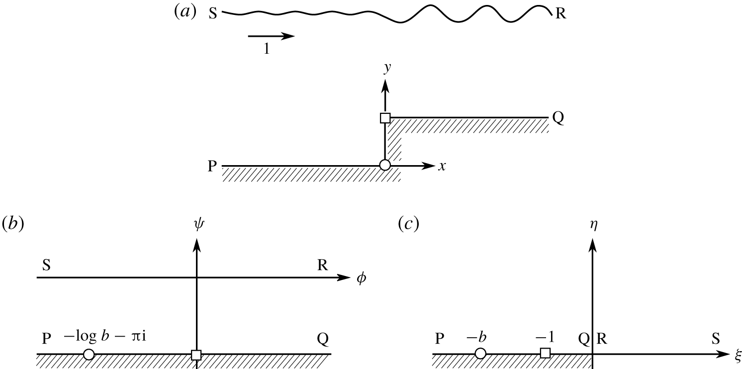
 $L$. The physical plane is shown in figure 4(a). The flow is non-dimensionalised using these characteristic scales, and we introduce complex physical coordinates,
 $z=x+\text{i}y$, with
 $x$ pointing along the channel, as well as a complex potential,
 $w=\unicode[STIX]{x1D719}+\text{i}\unicode[STIX]{x1D713}$. The governing equations for the fluid are then
 $$\begin{eqnarray}\displaystyle \text{Laplace's equation} & \unicode[STIX]{x1D6FB}^{2}\unicode[STIX]{x1D719}=0 & \displaystyle \text{inside the fluid},\end{eqnarray}$$
 $$\begin{eqnarray}\displaystyle \text{kinematic condition} & \unicode[STIX]{x1D735}\unicode[STIX]{x1D719}\boldsymbol{\cdot }\boldsymbol{n}=0 & \displaystyle \text{on solid/free surfaces},\quad\end{eqnarray}$$
 $$\begin{eqnarray}\displaystyle \text{Bernoulli's equation} & F^{2}|\unicode[STIX]{x1D735}\unicode[STIX]{x1D719}|^{2}/2+y+T\unicode[STIX]{x1D705}=\text{const.} & \displaystyle \text{on the free surface}.\end{eqnarray}$$
 $\boldsymbol{n}$ denotes a normal of the channel boundary and, in Bernoulli’s equation, the curvature,
 $\unicode[STIX]{x1D705}$, is defined to be positive when the centre of curvature lies inside the fluid. The derivation of this standard governing formulation is given in, for example, Vanden-Broeck (Reference Vanden-Broeck2010, chap. 2).
Flow over a step in a channel shown in the (a) physical  $z$ plane, (b) potential
 $w$ plane and (c) upper half-
 $\unicode[STIX]{x1D701}$ plane. In our non-dimensionalisation, the step corner (square) is chosen to be
 $\unicode[STIX]{x1D701}=-1$ and the stagnation point (circle) is chosen to be
 $\unicode[STIX]{x1D701}=-b$ with
 $b>1$. The labels P, Q, R, S show the orientation of the different mappings with respect to upstream and downstream locations.

In the analysis of the potential plane, it is convenient to choose the length scale to be
 $$\begin{eqnarray}L=\frac{h_{up}}{\unicode[STIX]{x03C0}},\end{eqnarray}$$
where  $h_{up}$ is the upstream height of the channel, and thus the non-dimensional height is set to
 $\unicode[STIX]{x03C0}$. We also non-dimensionalise the velocity according to its upstream value
 $U$, so that the non-dimensional flux is
 $\unicode[STIX]{x03C0}$. Setting
 $\unicode[STIX]{x1D713}=0$ on the free surface, it must then follow that
 $\unicode[STIX]{x1D713}=-\unicode[STIX]{x03C0}$ on the channel bottom and, consequently, the flow lies within a strip PQRS in the
 $w$ plane shown in figure 4(b).
It is convenient to further map the strip flow in the  $w$ plane to the upper half-
 $\unicode[STIX]{x1D701}$ plane using the conformal map
 $$\begin{eqnarray}\unicode[STIX]{x1D701}=\unicode[STIX]{x1D709}+\text{i}\unicode[STIX]{x1D702}=\text{e}^{-w}=\text{e}^{-(\unicode[STIX]{x1D719}+\text{i}\unicode[STIX]{x1D713})}.\end{eqnarray}$$
Thus, the free surface and channel bottom are both mapped to  $\unicode[STIX]{x1D702}=0$, with
 $\unicode[STIX]{x1D709}>0$ the free surface and
 $\unicode[STIX]{x1D709}<0$ the channel bottom. The flow in the upper half-
 $\unicode[STIX]{x1D701}$ plane is shown in figure 4(c), with the solid and fluid boundaries, marked PQRS, lying along the real axis.
Next, we introduce the complex velocity,  $\text{d}w/\text{d}z$, by writing
 $$\begin{eqnarray}\frac{\text{d}w}{\text{d}z}=q\text{e}^{-\text{i}\unicode[STIX]{x1D703}},\end{eqnarray}$$
for fluid speed  $q$ and streamline angle
 $\unicode[STIX]{x1D703}$. Below, we shall recast the original system (4.1) in terms of
 $q$ and
 $\unicode[STIX]{x1D703}$, written as functions of either
 $w$ or
 $\unicode[STIX]{x1D701}$.
Following the standard procedure, the requirement that  $\unicode[STIX]{x1D719}$ satisfies Laplace’s equation (4.1a) is equivalently restated as a boundary-integral relationship between
 $q$ and
 $\unicode[STIX]{x1D703}$ applied on the fluid and solid surfaces. For points on the free surface,
 $\unicode[STIX]{x1D709}\geqslant 0$, this allows us to write (cf. (3.4) in Trinh & Chapman (Reference Trinh and Chapman2013a))
 $$\begin{eqnarray}\log q(\unicode[STIX]{x1D709})=-\frac{1}{\unicode[STIX]{x03C0}}\left[\int _{-\infty }^{0}\frac{\unicode[STIX]{x1D703}(\unicode[STIX]{x1D709}^{\prime })}{\unicode[STIX]{x1D709}^{\prime }-\unicode[STIX]{x1D709}}\,\text{d}\unicode[STIX]{x1D709}^{\prime }+\unicode[STIX]{x2A0D}_{0}^{\infty }\frac{\unicode[STIX]{x1D703}(\unicode[STIX]{x1D709}^{\prime })}{\unicode[STIX]{x1D709}^{\prime }-\unicode[STIX]{x1D709}}\,\text{d}\unicode[STIX]{x1D709}^{\prime }\right].\end{eqnarray}$$
Above, the first integral on the right hand-side is known (since we assume that the channel geometry is specified via  $\unicode[STIX]{x1D703}$ for
 $\unicode[STIX]{x1D709}\leqslant 0$). The second integral is the Hilbert transform applied to the free surface, and the bar across the integral sign indicates a principal value.
In this work, we consider for convenience the case of flow over a right-angled step, given by specifying the streamline angles,
 $$\begin{eqnarray}\unicode[STIX]{x1D703}(\unicode[STIX]{x1D709})=\left\{\begin{array}{@{}ll@{}}0\quad & -\infty <\unicode[STIX]{x1D709}<-b,\\ \unicode[STIX]{x03C0}/2\quad & -b<\unicode[STIX]{x1D709}<-1,\\ 0\quad & -1<\unicode[STIX]{x1D709}<0,\end{array}\right.\end{eqnarray}$$
where  $b>1$ and
 $\unicode[STIX]{x1D709}=-b$ is the image of the stagnation point of the step in the
 $\unicode[STIX]{x1D701}$ plane. Substitution of (4.6) into the first integral on the right-hand side of (4.5) and integrating yields
 $$\begin{eqnarray}-\frac{1}{\unicode[STIX]{x03C0}}\int _{-\infty }^{0}\frac{\unicode[STIX]{x1D703}(\unicode[STIX]{x1D709}^{\prime })}{\unicode[STIX]{x1D709}^{\prime }-\unicode[STIX]{x1D709}}\,\text{d}\unicode[STIX]{x1D709}^{\prime }=\log q_{s},\quad \text{where }q_{s}(\unicode[STIX]{x1D709})\equiv \left(\frac{\unicode[STIX]{x1D709}+b}{\unicode[STIX]{x1D709}+1}\right)^{1/2}.\end{eqnarray}$$
In (4.7), we have defined the important ‘shape function’,  $q_{s}$, which encodes the channel-bottom geometry and plays a critical role in the work that follows.
Returning to the second integral on the right-hand side of (4.5), we shall also define the Hilbert transform operator  $\mathscr{H}$, defined on the free surface
 $\unicode[STIX]{x1D709}\geqslant 0$ by
 $$\begin{eqnarray}\mathscr{H}[\unicode[STIX]{x1D703}](\unicode[STIX]{x1D709})\equiv -\frac{1}{\unicode[STIX]{x03C0}}\unicode[STIX]{x2A0D}_{0}^{\infty }\frac{\unicode[STIX]{x1D703}(\unicode[STIX]{x1D709}^{\prime })}{\unicode[STIX]{x1D709}^{\prime }-\unicode[STIX]{x1D709}}\,\text{d}\unicode[STIX]{x1D709}^{\prime },\end{eqnarray}$$
so that the boundary-integral equation (4.5) can be written compactly as
 $$\begin{eqnarray}\log q(\unicode[STIX]{x1D709})=\log q_{s}(\unicode[STIX]{x1D709})+\mathscr{H}[\unicode[STIX]{x1D703}](\unicode[STIX]{x1D709}),\end{eqnarray}$$
which is to be satisfied along the free surface,  $\unicode[STIX]{x1D709}\geqslant 0$.
To close the system, Bernoulli’s equation in (4.1c) is written in terms of  $q$ and
 $\unicode[STIX]{x1D703}$ using (4.4). Thus, along the free surface
 $\unicode[STIX]{x1D713}=0$, we have
 $$\begin{eqnarray}F^{2}\left[q^{2}\frac{\text{d}q}{\text{d}\unicode[STIX]{x1D719}}\right]-T\left[q^{2}\frac{\text{d}^{2}\unicode[STIX]{x1D703}}{\text{d}\unicode[STIX]{x1D719}^{2}}+q\frac{\text{d}q}{\text{d}\unicode[STIX]{x1D719}}\frac{\text{d}\unicode[STIX]{x1D703}}{\text{d}\unicode[STIX]{x1D719}}\right]=-\sin \unicode[STIX]{x1D703}.\end{eqnarray}$$
The object now is to solve the integro-differential system given by the boundary integral (4.9a) and Bernoulli’s equation (4.9b) for the unknowns,  $q$ and
 $\unicode[STIX]{x1D703}$, along the free surface given by
 $\unicode[STIX]{x1D709}\geqslant 0$ or equivalently
 $-\infty <\unicode[STIX]{x1D719}<\infty$ and
 $\unicode[STIX]{x1D713}=0$. Note, however, that for computational purposes we must write (4.8) as
 $$\begin{eqnarray}\mathscr{H}[\unicode[STIX]{x1D703}](\unicode[STIX]{x1D719})=-\frac{1}{\unicode[STIX]{x03C0}}\left(\int _{-\infty }^{-\unicode[STIX]{x1D6F7}}+\,\unicode[STIX]{x2A0D}_{-\unicode[STIX]{x1D6F7}}^{\unicode[STIX]{x1D6F7}}+\int _{\unicode[STIX]{x1D6F7}}^{\infty }\right)\frac{\unicode[STIX]{x1D703}(\text{e}^{-\unicode[STIX]{x1D719}^{\prime }})}{\text{e}^{-\unicode[STIX]{x1D719}^{\prime }}-\text{e}^{-\unicode[STIX]{x1D719}}}(-\text{e}^{-\unicode[STIX]{x1D719}^{\prime }})\,\text{d}\unicode[STIX]{x1D719}^{\prime },\end{eqnarray}$$
where  $\pm \unicode[STIX]{x1D6F7}$ are the limits of the computational domain. The standard approach is to discard the first and third terms in (4.10), which is known to introduce errors into the solution. These errors can be reduced by instead approximating the first and third terms by asymptotic solutions in the far field, which was done for flow over a cylinder in Grandison & Vanden-Broeck (Reference Grandison and Vanden-Broeck2006). Thus the numerical treatment of the Hilbert transform is key to satisfying the radiation condition.
4.1 Challenges in solving the full problem
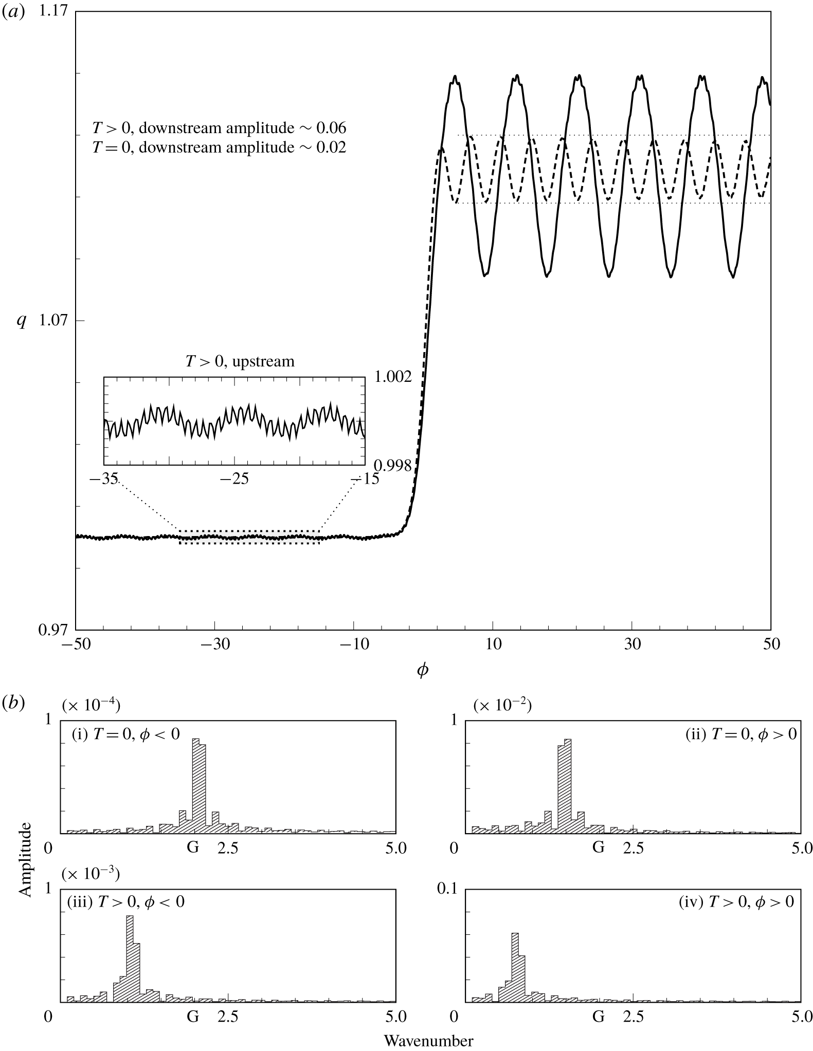
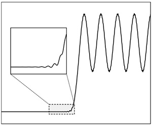
The main challenge that confronts us in solving (4.9) is illustrated by figure 5(a), which shows two numerical solutions, one without surface tension ( $T=0$, dashed) and one with a small amount of surface tension (
 $T=2.5\times 10^{-3}$, solid). To produce figure 5, we discretise equations (4.9) using finite differences and solve the resulting nonlinear system using Newton’s method. This approach is used in the majority of the works referenced above (Forbes & Schwartz Reference Forbes and Schwartz1982; Forbes Reference Forbes1983; King & Bloor Reference King and Bloor1987) and is described in detail in Vanden-Broeck (Reference Vanden-Broeck2010).
Figure 5(b) shows the Fourier spectra of the solutions  $q(\unicode[STIX]{x1D719})$, divided into either upstream or downstream components. Spectra (i) and (ii) correspond to
 $T=0$, while spectra (iii) and (iv) correspond to
 $T\neq 0$. In this and all subsequent figures, Fourier spectra are calculated as follows: First, the solution,
 $q$, is interpolated onto a regular grid and the relevant upstream (
 $\unicode[STIX]{x1D719}<0$) or downstream portions (
 $\unicode[STIX]{x1D719}>0$) extracted. The Fourier transform is taken and the results shown as a bar graph. On the (angular) wavenumber axis of each spectrum, we mark predicted gravity and capillary wavenumbers with a ‘G’ and ‘C’ as required, according to the predictions of §§ 2 and 3.
Solutions to the boundary-integral equations (4.9). (a) Boundary-integral solutions for flow over a step of non-dimensional height 0.2 at Froude number  $F^{2}=0.5$, for
 $T=0$ (dashed curve) and
 $T=2.5\times 10^{-3}$ (solid curve) with
 $N=800$ grid points. Shown is the surface speed
 $q$, as a function of the velocity potential
 $\unicode[STIX]{x1D719}$. (b) Fourier spectra for
 $q$, showing, respectively, the (i) upstream gravity flow, (ii) downstream gravity flow, (iii) upstream gravity–capillary flow, and (iv) downstream gravity–capillary flow. On each spectrum, ‘G’ denotes the gravity wavenumber predicted by the dispersion relation (3.3). The predicted capillary wavenumber for the
 $T>0$ flow is
 $k=198$.

There are three types of error visible in figure 5.
(i) The gravity-only flow (dashed curve) should consist of constant-amplitude waves downstream and a flat (or exponentially decaying) surface upstream. However, the dotted horizontal guides show that the downstream waves are distorted over the last few periods. This distortion is primarily associated with errors in evaluating the truncated Hilbert transform (4.8). The transform is expressed as an integration over the whole real line, but must be truncated to a finite computational domain.
(ii) Still for
$T=0$, the Fourier spectrum (i) shows that there are small gravity waves upstream. The radiation condition requires that only capillary waves exist upstream, so these waves are unphysical.(iii) Such errors become even more problematic for the flow with surface tension,
$T=2.5\times 10^{-3}$. The solid curve in figure 5(a) demonstrates the presence of spurious waves upstream, as seen by the inset. For this value of $(F,T)$ the non-dimensional capillary wavenumber is $k=198$, but the upstream Fourier spectrum in figure 5(biii) shows that the dominant frequency is approximately one. Just as in the gravity-only flow, the solution does not satisfy the radiation condition. Furthermore, the spectrum in figure 5(biv) confirms that the downstream waves are not of the correct gravity-associated wavenumber, either.


Convergence of the numerical scheme is more difficult at larger values of  $T$. We emphasise that, although the capillary waves shown in the inset of figure 5(a) are not well resolved, the issues (i) to (iii) are not functions of the grid spacing or numerical tolerances.
Our figure 5 takes inspiration from figure 3 of Forbes (Reference Forbes1983), who provided some initial discussion of the radiation problem for flow over a semicircular cylinder. Forbes (Reference Forbes1983) further indicated that, without knowledge of the proper boundary conditions, it was unclear how numerical solutions could be obtained for more nonlinear flows. Similar comments on the difficulty of the radiation problem appear in the works of, for example, Forbes & Schwartz (Reference Forbes and Schwartz1982), Scullen (Reference Scullen1998), Părău & Vanden-Broeck (Reference Părău and Vanden-Broeck2002) and Grandison & Vanden-Broeck (Reference Grandison and Vanden-Broeck2006) for a variety of free-surface problems.
5 Reduced models for gravity–capillary waves
The preceding discussion makes clear that one problem with numerical computation of steady-state gravity–capillary waves is the truncation of the Hilbert transform,  $\mathscr{H}$, and the inability to correctly apply the radiation condition. In fact, as was argued by Trinh (Reference Trinh2016, Reference Trinh2017), in the low-Froude-number and low-Bond-number limit
 $\unicode[STIX]{x1D716}\rightarrow 0$, the Hilbert transform can be systematically removed and the governing system (4.9) reduced. Here we present only the ideas that are most relevant to the reduction. Detailed calculations are given in appendix A. A full comparison of reduced models for gravity-only flow is given in Trinh (Reference Trinh2017).
5.1 Removing the Hilbert transform
For the purpose of developing the reduced model, it is important to consider three main points that emerge as a result of exponential asymptotics (Chapman & Vanden-Broeck Reference Chapman and Vanden-Broeck2006). Firstly, in the limit  $\unicode[STIX]{x1D716}\rightarrow 0$, free-surface waves are associated with singularities in the analytic continuation of the leading-order solution
 $q_{s}$, given by (4.7). These singularities lie in the complex plane, so it is necessary to write complex versions of the governing equations. That is, we extend
 $\unicode[STIX]{x1D719}$ to the complex plane, and rewrite
 $\unicode[STIX]{x1D719}\mapsto w\in \mathbb{C}$. Similarly, we rewrite
 $\unicode[STIX]{x1D709}\mapsto \unicode[STIX]{x1D701}\in \mathbb{C}$. Care must be taken when defining the Hilbert transform (4.8) in the complex plane so as to preserve the principal-value behaviour as
 $\unicode[STIX]{x1D701}$ approaches the real axis. This is accomplished through a small deformation of the path of integration about the point of evaluation, which contributes a residue term.
The complex versions of the governing equations are thus
 $$\begin{eqnarray}\displaystyle & \displaystyle \unicode[STIX]{x1D6FD}\unicode[STIX]{x1D716}q^{2}q^{\prime }-\unicode[STIX]{x1D6FD}\unicode[STIX]{x1D70F}\unicode[STIX]{x1D716}^{2}(q^{2}\unicode[STIX]{x1D703}^{\prime \prime }+qq^{\prime }\unicode[STIX]{x1D703}^{\prime })+\sin \unicode[STIX]{x1D703}=0, & \displaystyle\end{eqnarray}$$
 $$\begin{eqnarray}\displaystyle & \displaystyle \log q-\text{i}\unicode[STIX]{x1D703}+\hat{\mathscr{H}}[\unicode[STIX]{x1D703}]-\log q_{s}=0, & \displaystyle\end{eqnarray}$$
 $^{\prime }$) denote differentiation in
 $w$ and where we have defined
 $$\begin{eqnarray}\hat{\mathscr{H}}[\unicode[STIX]{x1D703}](\unicode[STIX]{x1D701})=\frac{1}{\unicode[STIX]{x03C0}}\int _{0}^{\infty }\frac{\unicode[STIX]{x1D703}(\unicode[STIX]{x1D709}^{\prime })}{\unicode[STIX]{x1D709}^{\prime }-\unicode[STIX]{x1D701}}\,\text{d}\unicode[STIX]{x1D709}^{\prime }.\end{eqnarray}$$
Now in the system (5.1), we have moved from the free surface, where  $q$ and
 $\unicode[STIX]{x1D719}\in \mathbb{R}$, to the complex upper half-plane, where
 $q$ and
 $\unicode[STIX]{x1D719}=w\in \mathbb{C}$, and so solutions are complex-valued. To return to the free surface, where the solution is real, we must account for the contribution from the lower half-plane. This is done by adding
 $q$ to its complex conjugate,
 $q^{\ast }$. Understandably, these ideas of analytic continuation are subtle, but for more details we refer readers to §§5.1 and 8.4 of Trinh (Reference Trinh2017).
Next, in the limit  $\unicode[STIX]{x1D716}\rightarrow 0$, we expect that the solution,
 $q$, can be split into a base series
 $q_{r}$, which describes the mean flow, and a remainder term
 $\bar{q}$, which describes the waves (cf. Ogilvie Reference Ogilvie1968; Chapman & Vanden-Broeck Reference Chapman and Vanden-Broeck2006). The base series is the regular asymptotic expansion in powers of
 $\unicode[STIX]{x1D716}$ with, say,
 $N$ terms, and the remainder is
 $O(\unicode[STIX]{x1D716}^{N})$. Thus we have
 $$\begin{eqnarray}q=q_{r}+\bar{q}=\mathop{\sum }_{n=0}^{N-1}\unicode[STIX]{x1D716}^{n}q_{n}+\bar{q}.\end{eqnarray}$$
We also do the same for  $\unicode[STIX]{x1D703}$. The inclusion of the remainder term in (5.3) is necessary because using a regular expansion alone predicts a flat surface at every algebraic order. In the low-speed limit, the waves are exponentially small and must be found with specialised techniques from exponential asymptotics.
Finally, a careful analysis of the governing equations using the split solution (5.3) reveals that computation of the mean speed  $q_{r}$ only involves the Hilbert transform of known terms, that is,
 $\hat{\mathscr{H}}[\unicode[STIX]{x1D703}_{r}]$. Further, the remainder term
 $\bar{q}$, and hence the form of the waves, does not depend on the Hilbert transform of
 $\bar{\unicode[STIX]{x1D703}}$ at leading order. Therefore the problematic term
 $\hat{\mathscr{H}}[\bar{\unicode[STIX]{x1D703}}]$ can be ignored in an asymptotically consistent way in the limit as
 $\unicode[STIX]{x1D716}\rightarrow 0$. Equation (5.1b) reduces to the simple relationship
 $$\begin{eqnarray}\bar{q}=\text{i}q_{s}\bar{\unicode[STIX]{x1D703}},\end{eqnarray}$$
which can be substituted into (5.1a) to give an ordinary differential equation (ODE) for  $\bar{q}$, which is known as a reduced model.
5.2 Choosing the truncation value $N$

The derivation of the reduced model for an arbitrary truncation value  $N$ is given in appendix A, but here we focus on the case
 $N=2$. This particular value of
 $N$ is chosen because it captures the functional form of the waves (Trinh Reference Trinh2017). In the limit
 $\unicode[STIX]{x1D716}\rightarrow 0$, we expect the form of the waves to be
 $$\begin{eqnarray}\bar{q}\sim {\mathcal{A}}{\mathcal{F}}(w)\text{e}^{-\unicode[STIX]{x1D712}(w)/\unicode[STIX]{x1D716}}.\end{eqnarray}$$
If the base series (5.3) is truncated at  $N=1$, then the resulting
 $N=1$ reduced model produces a solution with the correct phase function
 $\unicode[STIX]{x1D712}(w)$. The
 $N=2$ reduced model produces a solution where both
 $\unicode[STIX]{x1D712}$ and
 ${\mathcal{F}}$ are correct. To obtain the constant pre-factor
 ${\mathcal{A}}$, one must truncate the base series at the optimal point
 ${\mathcal{N}}(\unicode[STIX]{x1D716})$, where it is shown in Chapman & Vanden-Broeck (Reference Chapman and Vanden-Broeck2006) that
 ${\mathcal{N}}\rightarrow \infty$ as
 $\unicode[STIX]{x1D716}\rightarrow 0$. The choice of
 $N=2$ therefore correctly predicts the form of the waves, up to a multiplicative constant
 ${\mathcal{A}}$ (Trinh Reference Trinh2017).
5.3 The $N=2$ reduced model for the low-Froude-number, low-Bond-number limit

The first two terms in the truncated base series (5.3) are
 $$\begin{eqnarray}\displaystyle & \displaystyle \unicode[STIX]{x1D703}_{0}=0, & \displaystyle\end{eqnarray}$$
 $$\begin{eqnarray}\displaystyle & \displaystyle q_{0}=q_{s}, & \displaystyle\end{eqnarray}$$
 $$\begin{eqnarray}\displaystyle & \displaystyle \unicode[STIX]{x1D703}_{1}=-\unicode[STIX]{x1D6FD}q_{s}^{2}\frac{\text{d}q_{s}}{\text{d}w}, & \displaystyle\end{eqnarray}$$
 $$\begin{eqnarray}\displaystyle & \displaystyle q_{1}=q_{s}(\text{i}\unicode[STIX]{x1D703}_{1}-\hat{\mathscr{H}}[\unicode[STIX]{x1D703}_{1}]), & \displaystyle\end{eqnarray}$$
 $\hat{\mathscr{H}}[\unicode[STIX]{x1D703}_{1}]$ may be evaluated explicitly, so that all terms in (5.6) may be written in closed form. Using the relationship (5.4), we may rewrite (5.1a) as an equation for
 $\bar{q}$, the
 $N=2$ reduced model. This last substitution involves a fair amount of algebra, and so the derivation of this equation is outlined in appendix A. The
 $N=2$ reduced model is given by
 $$\begin{eqnarray}\displaystyle & & \displaystyle \displaystyle \text{i}\unicode[STIX]{x1D6FD}\unicode[STIX]{x1D70F}\unicode[STIX]{x1D716}^{2}(q_{s}+\unicode[STIX]{x1D716}q_{1})\bar{q}^{\prime \prime }+(\unicode[STIX]{x1D6FD}\unicode[STIX]{x1D716}q_{s}^{2}+2\unicode[STIX]{x1D6FD}\unicode[STIX]{x1D716}^{2}q_{s}q_{1}-\text{i}\unicode[STIX]{x1D6FD}\unicode[STIX]{x1D70F}\unicode[STIX]{x1D716}^{2}q_{s}^{\prime })\bar{q}^{\prime }\nonumber\\ \displaystyle & & \displaystyle \quad \displaystyle +\left(-\frac{\text{i}}{q_{s}}+\unicode[STIX]{x1D716}\frac{\text{i}q_{1}}{q_{s}^{2}}+2\unicode[STIX]{x1D6FD}\unicode[STIX]{x1D716}q_{s}q_{s}^{\prime }\right)\bar{q}+\unicode[STIX]{x1D716}^{2}\left(\frac{\text{i}q_{1}^{2}}{2q_{s}^{2}}+2\unicode[STIX]{x1D6FD}q_{s}q_{s}^{\prime }q_{1}+\unicode[STIX]{x1D6FD}q_{s}^{2}q_{1}^{\prime }\right)=0.\end{eqnarray}$$
In deriving (5.7) we have chosen to include terms only up to  $O(\unicode[STIX]{x1D716})$, bearing in mind the ansatz (5.5), which means that derivatives of
 $\bar{q}$ contribute a factor of
 $1/\unicode[STIX]{x1D716}$. The leading-order forcing term is
 $O(\unicode[STIX]{x1D716}^{2})$. The reduced model (5.7) is a linear ODE with known coefficients, to be solved for
 $\bar{q}$. Thus (5.7) is computationally much more convenient than the full system (4.9), as the latter includes a non-local term via the Hilbert transform. Moreover, it is much simpler to apply the radiation condition to the reduced model than to the full system, and so we can be sure of selecting the unique physically relevant solution.
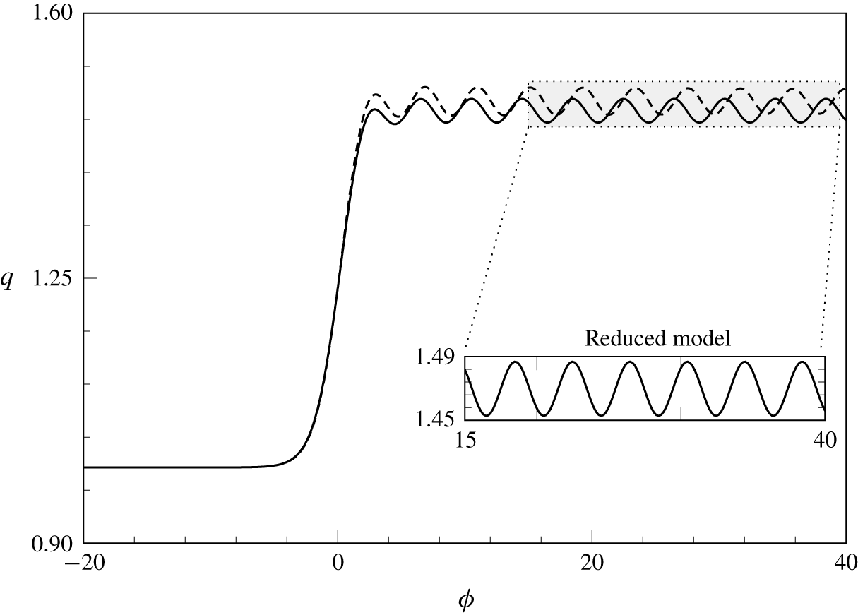
Comparison of the full boundary-integral equations (4.9) (dashed curve) and the  $N=2$ reduced model (5.7) (solid curve) for gravity-only flow. The step height
 $b=2$ and
 $\unicode[STIX]{x1D716}=0.2$ (
 $\unicode[STIX]{x1D6FD}$ may be set to unity without loss of generality). The inset shows that the reduced model produces constant-amplitude waves downstream.

Figure 6 compares numerical solutions to the full system (4.9) (dashed curve) and the reduced model (5.7) (solid curve) for gravity-only flow (i.e. with  $\unicode[STIX]{x1D70F}=0$). In this case, the radiation condition requires that the upstream surface is flat and it is sufficient to solve (5.7) by imposing the condition
 $\bar{q}=0$ at the first mesh point (only one condition is needed, as the gravity-only problem is first-order). Note that the reduced model produces constant-amplitude waves downstream, whereas the boundary-integral formation does not (cf. figure 5a). The reduced model therefore produces constant-amplitude waves of the correct frequency, but nevertheless does not agree with the boundary-integral solution downstream. This is due to truncation at
 $N=2$ terms.
5.4 Choosing the boundary conditions
For gravity–capillary flows, it is insufficient to treat (5.7) as an initial-value problem (i.e. ‘shooting’ from upstream). In particular, Type I solutions have constant-amplitude capillary waves that extend upstream to  $-\infty$, so the values of
 $\bar{q}$ and
 $\bar{q}^{\prime }$ at the first mesh point are not known a priori. Even in regimes where the upstream waves decay, however, we found that enforcing a flat surface at the first mesh point leads to inaccurate and unphysical results. Instead, we treat (5.7) as a boundary-value problem with Sommerfeld boundary conditions at either end, using wavenumbers that satisfy the radiation condition. These wavenumbers were derived in § 3. Thus we solve (5.7) with the boundary conditions
 $$\begin{eqnarray}\bar{q}^{\prime }+\text{i}k\bar{q}=0\end{eqnarray}$$
at the first and last mesh points, where  $k$ is the relevant wavenumber given by (3.4) and (3.5) upstream and downstream, respectively. By imposing (5.8) we have restricted ourselves to flows where the far-field solution is a train of linear waves (either constant-amplitude or decaying). However, this is clearly not the only possibility, and indeed (5.8) only allows us to recover one of the four new classes of waves described in Trinh & Chapman (Reference Trinh and Chapman2013b).
6 Results
Here we present numerical results for the  $N=2$ reduced model, and explore the low-Froude-number, low-Bond-number limit of the bifurcation diagram in figure 3 to validate the existence of the new (Type III) solutions described in Trinh & Chapman (Reference Trinh and Chapman2013b). With the boundary conditions (5.8) applied at either end of the computational domain, we are able to obtain good solutions to the
 $N=2$ model for a wide range of parameters. By keeping the values of
 $\unicode[STIX]{x1D6FD}$,
 $b$ and
 $\unicode[STIX]{x1D716}$ fixed (at 1, 2 and 0.5, respectively) and increasing
 $\unicode[STIX]{x1D70F}$, we move up the vertical axis on figure 3 and vary the value of
 $A=4\unicode[STIX]{x1D70F}/\unicode[STIX]{x1D6FD}$.
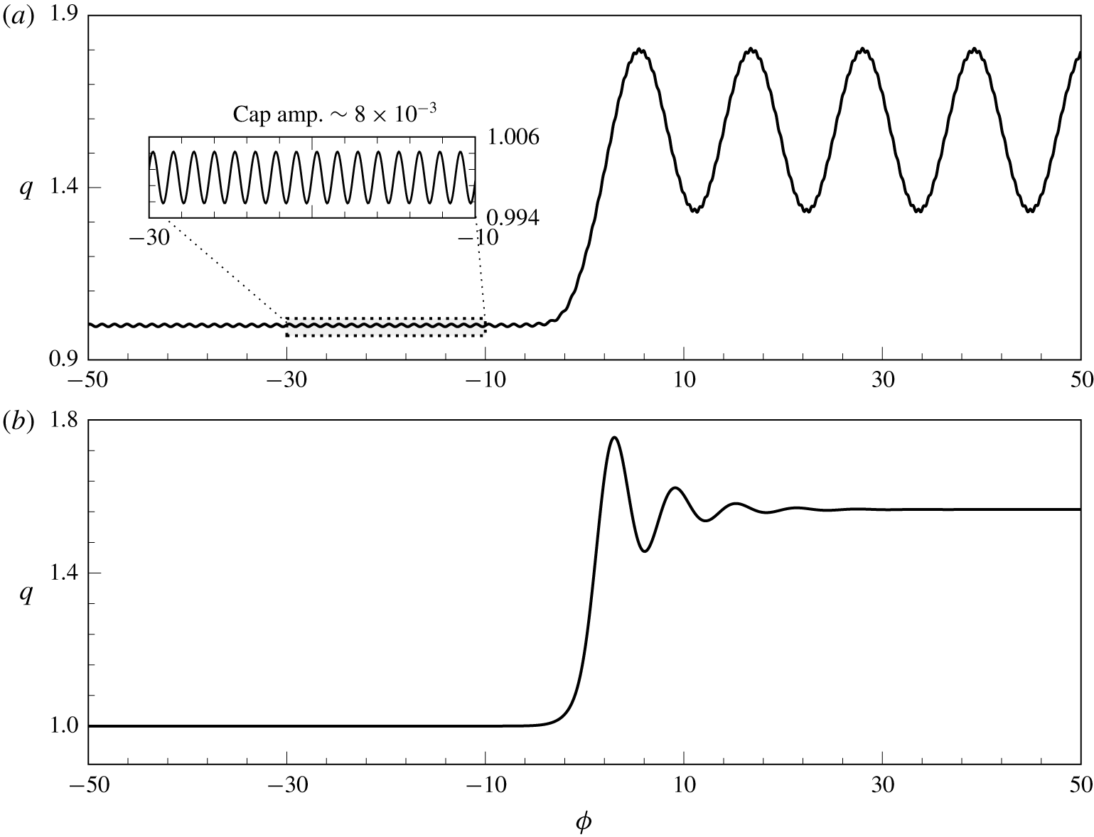
Solutions to the  $N=2$ reduced model (5.7) as a boundary-value problem with Sommerfeld conditions (5.8) at either end. The parameters are
 $\{b,\unicode[STIX]{x1D716},\unicode[STIX]{x1D6FD}\}=\{2,0.5,1\}$ and the value of
 $\unicode[STIX]{x1D70F}$ is chosen so that each panel shows a solution of a different type (see figure 3): (a) Type I solution with
 $\unicode[STIX]{x1D70F}=0.24$, and (b) Type II solution with
 $\unicode[STIX]{x1D70F}=1.5$. Fourier spectra for solution (a) are shown in figure 9(a,b).

Figure 7 shows the two classical solutions that exist when the geometry is linear, but computed with  $b=2$ (i.e. in a nonlinear geometry). Figure 7(a) shows a type I solution with
 $\unicode[STIX]{x1D70F}=0.24$ and thus
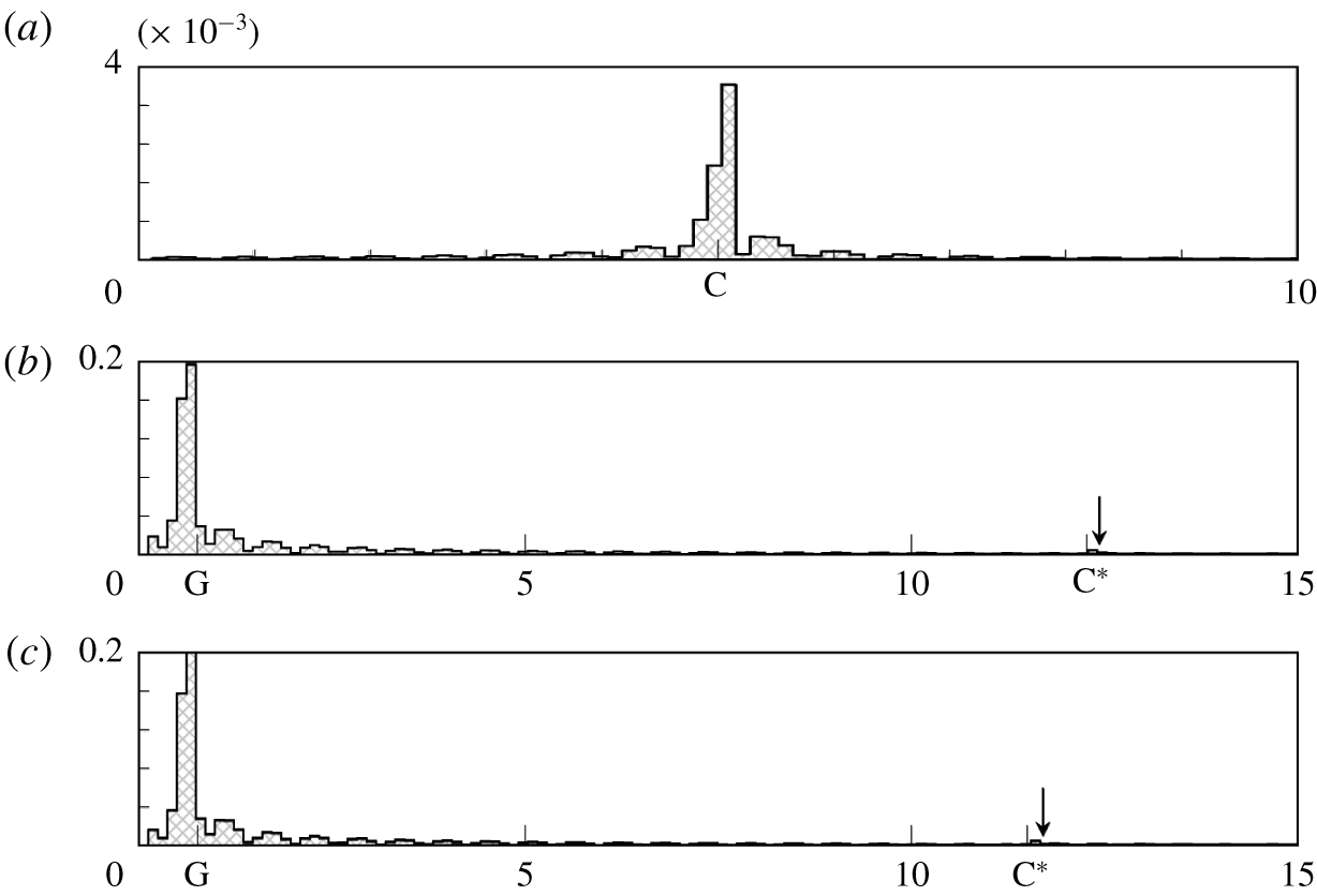
 $A=0.96<1$, with constant-amplitude waves upstream and downstream. We see that the downstream and, via the inset, upstream solutions are both correctly resolved. The Fourier spectra for this solution are given in figure 9(a,b), and confirm that the dominant wavenumbers agree with the predictions from § 3, denoted G and C, and thus that the radiation condition is satisfied. However, the downstream solution is not completely ‘clean’ and small disturbances are visible on top of the main gravity waves, visible as a small peak in the spectrum at
 $k\approx 12$; this is shown with an arrow in figure 9(b) and is discussed further in § 6.1. Figure 7(b) shows a Type II solution, with
 $\unicode[STIX]{x1D70F}=1.5$ and thus
 $A=6>b^{2}$. This is the solitary-wave solution from Rayleigh’s original classification, and has waves that decay in the far field both upstream and downstream.
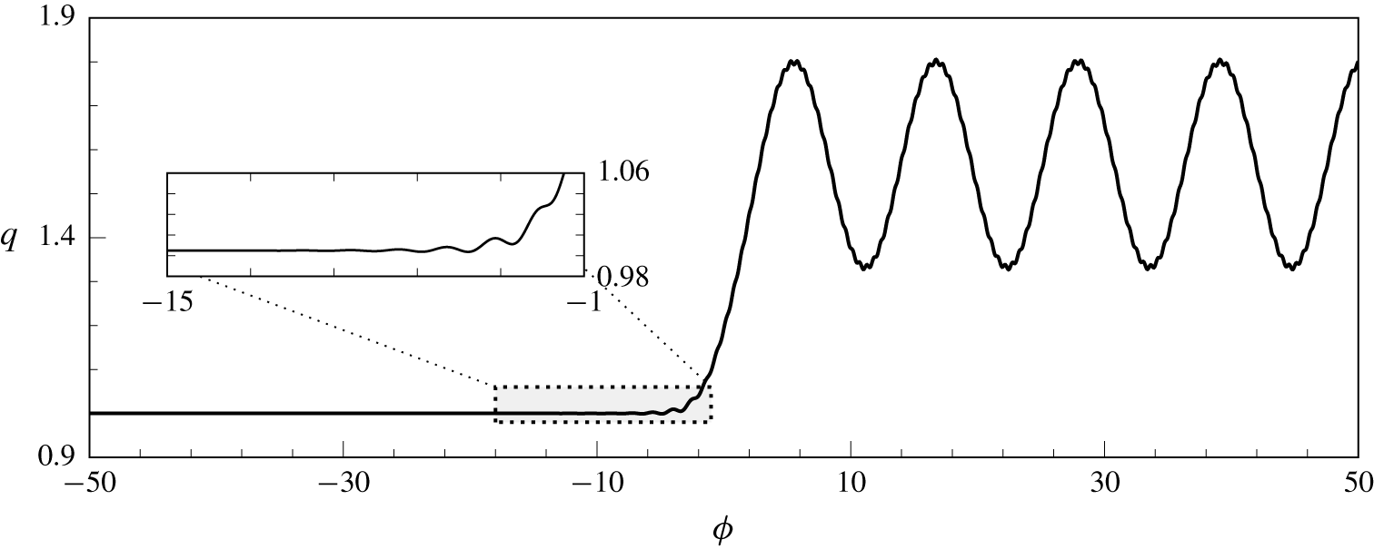
Figure 8 shows a Type III solution with  $\unicode[STIX]{x1D70F}=0.255$ and thus
 $A=1.02\in [1,b^{2}]$. This is one of the new waves from Trinh & Chapman (Reference Trinh and Chapman2013b), predicted to exist when the step height,
 $b-1$, is
 $O(1)$ in size. There are constant-amplitude waves downstream, but upstream the waves decay away from the step. This is shown in greater detail in the inset. The region over which the waves decay is predicted to increase as
 $A\rightarrow 1$, and tests with various values of
 $\unicode[STIX]{x1D70F}$ (not shown) confirm this. The downstream spectrum is shown in figure 9(c), and shows that the dominant frequency of the downstream solution is correct, again with a small secondary peak near the label C*.
Type III solution to the  $N=2$ reduced model, representing one of the new classes of waves from Trinh & Chapman (Reference Trinh and Chapman2013b). The parameters are as in figure 7, but with
 $\unicode[STIX]{x1D70F}=0.255$ so that
 $1<A<b^{2}$. The Fourier spectrum of the downstream solution is shown in figure 9(c).

(a) Upstream and (b) downstream Fourier spectra for figure 7(a). (c) Downstream Fourier spectrum for figure 8. The horizontal axes correspond to wavenumber  $k$ and the vertical axis indicates the absolute value of the
 $k$th mode. Labels G and C correspond to gravity and capillary wavenumbers from § 3, while C* corresponds to the wavenumber from § 6.1.

In summary, the careful application of the Sommerfeld boundary condition (5.8) to the  $N=2$ reduced model (5.7) confirms the existence of one new class of waves predicted in Trinh & Chapman (Reference Trinh and Chapman2013b) for flow over a rectangular step. These solutions satisfy the radiation condition via the Sommerfeld boundary condition, which uses wavenumbers derived in § 3. This is confirmed by the Fourier spectra in figure 9. However, when
 $\unicode[STIX]{x1D716}=O(1)$ these wavenumbers are no longer valid, and this leads to interference in the solutions. We will now discuss this in more detail.
6.1 The appearance of beating for larger values of $\unicode[STIX]{x1D716}$

Both the dispersion relation (3.3) and the  $N=2$ reduced model (5.7) are derived from the full water-wave problem in the limit
 $\unicode[STIX]{x1D716}\rightarrow 0$. Thus for
 $\unicode[STIX]{x1D716}$ sufficiently small, solutions to (5.7) computed using (3.3) satisfy the radiation condition. For larger values of
 $\unicode[STIX]{x1D716}$, spurious secondary waves appear in the
 $N=2$ model, creating the ‘beating’ effect seen downstream in figure 7(a). The secondary waves arise due to interference between the two linearly independent solutions of the second-order ODE (5.7), which diverges from solutions of the full problem when
 $\unicode[STIX]{x1D716}=O(1)$. The beating is an indication that the reduced model is being used outside its range of validity, as the low-speed dispersion relation (3.3) no longer predicts the far-field behaviour of the solution.
To confirm this, we can derive the far-field behaviour of (5.7) directly from the equation itself, and see that it differs from (3.3) when  $\unicode[STIX]{x1D716}=O(1)$. If we let
 $|\unicode[STIX]{x1D719}|\rightarrow \infty$, both
 $q_{0}=q_{s}$ and
 $q_{1}$ tend to constant values:
 $$\begin{eqnarray}\displaystyle \left.\begin{array}{@{}c@{}}q_{s}\rightarrow 1\quad \text{and}\quad q_{1}\rightarrow 0\quad \text{as }\unicode[STIX]{x1D719}\rightarrow -\infty ,\\[5.0pt] q_{s}\rightarrow \sqrt{b}\quad \text{and}\quad q_{1}\rightarrow \unicode[STIX]{x1D6FD}\left({\displaystyle \frac{b^{2}-\sqrt{b}}{3\unicode[STIX]{x03C0}}}\right)\quad \text{as }\unicode[STIX]{x1D719}\rightarrow \infty ,\end{array}\right\} & & \displaystyle\end{eqnarray}$$
so that, far away from the step, (5.7) is a linear ODE with constant coefficients. The two linearly independent solutions have wavenumbers given by
 $$\begin{eqnarray}{\mathcal{K}}_{\pm }=\text{i}\frac{q_{s}^{3}\unicode[STIX]{x1D6FD}+2q_{1}q_{s}^{2}\unicode[STIX]{x1D6FD}\unicode[STIX]{x1D716}\pm \sqrt{\unicode[STIX]{x1D6E5}}}{2q_{s}\unicode[STIX]{x1D6FD}\unicode[STIX]{x1D716}(q_{s}+\unicode[STIX]{x1D716}q_{1})\unicode[STIX]{x1D70F}},\end{eqnarray}$$
where
 $$\begin{eqnarray}\unicode[STIX]{x1D6E5}=\unicode[STIX]{x1D6FD}[q_{s}^{4}\unicode[STIX]{x1D6FD}(q_{s}+2\unicode[STIX]{x1D716}q_{1})^{2}-4(q_{s}-\unicode[STIX]{x1D716}q_{1})(q_{s}+\unicode[STIX]{x1D716}q_{1})\unicode[STIX]{x1D70F}].\end{eqnarray}$$
Comparing (6.2a) with (3.3), we see that  ${\mathcal{K}}_{\pm }$ agrees with the upstream wavenumber
 $k_{up}$ for all
 $\unicode[STIX]{x1D716}$, but agrees with the downstream wavenumber
 $k_{down}$ only in the limit
 $\unicode[STIX]{x1D716}\rightarrow 0$. Thus if
 $k_{up}$ and
 $k_{down}$ are used in the Sommerfeld boundary conditions when
 $\unicode[STIX]{x1D716}=O(1)$, beating is observed due to the discrepancy between
 ${\mathcal{K}}_{\pm }$ and
 $k_{down}$. The downstream spectra shown in figure 9(b,c) confirm that the secondary waves visible in figures 7(a) and 8 have the frequency predicted by (6.2a) (marked C* on the axis). Thus the interference visible in the solution is due to the use of
 $k_{down}$ in the downstream boundary condition in a regime where the far-field solution has frequency
 ${\mathcal{K}}_{+}$.
Thus the appearance of beating is a sign that the  $N=2$ equation is reaching its limit of validity. Recall that both the dispersion relation (3.3) and the
 $N=2$ reduced model are valid asymptotic limits of the full problem when
 $\unicode[STIX]{x1D716}\rightarrow 0$; however, the wavenumbers
 ${\mathcal{K}}_{\pm }$ given in (6.2a) are valid for the
 $N=2$ equation at any
 $\unicode[STIX]{x1D716}$. Thus if the reduced model is to remain relevant in the context of the full problem, it is important that
 $\unicode[STIX]{x1D716}$ is kept small enough that (3.3) is still valid and beating does not occur.
7 Conclusions
In order to compute steady-state gravity–capillary flow past nonlinear geometries, specialised methods are needed to select the solution that satisfies the radiation condition. In § 5, we showed that the full problem can be reduced to a linear ODE using techniques from exponential asymptotics to justify removing the problematic Hilbert transform term. This reduction is valid in the low-Froude-number, low-Bond-number limit, but places no restriction on the size of the step. This ODE was still found to be very sensitive in the sense that precise boundary conditions were needed to select solutions that satisfy the radiation condition, but this is computationally simpler to implement in the reduced model than in the boundary-integral framework of the full problem. The relevant boundary conditions were derived in § 2 by considering different dispersion relations up- and downstream.
With these boundary conditions, we were able to verify numerically the existence of new waves from Trinh & Chapman (Reference Trinh and Chapman2013b) for flow over a right-angled step, and to confirm that Rayleigh’s original bifurcation curve separates into a band when the size of the obstacle is too large to be linearised about. This was done in § 6, where one of the new classes of waves (decaying upstream, constant-amplitude downstream) was found to exist in an intermediate region between the two classical solutions (cf. figure 8).
7.1 Difficulties in applications to the full problem
One of the aims of developing these reduced models is to see whether their solutions can provide a starting guess for the iterative methods needed to solve the system of equations that make up the full boundary-integral problem (5.1).
The authors ran several numerical experiments, using solutions from the  $N=2$ equation (5.7) as starting guesses for the full problem. Experiments were run with a large number (≈2000) of grid points and moderate parameter values (
 $b=1.7,~\unicode[STIX]{x1D716}=0.5$), but these failed to converge to the correct solutions. Even on occasions where Newton’s method produced a result, the upstream wavenumbers were in serious error, and the accuracy is not significantly improved compared to solutions obtained using the initial guess
 $\unicode[STIX]{x1D703}=0$. As discussed in § 5.2, the
 $N=2$ model produces solutions that differ from the full problem by a multiplicative constant. This can be seen in the gravity-only case in figure 6, which compares solutions of the
 $N=2$ model and the full problem. Although the reduced model captures the wavelength correctly, there is a persistent error in amplitude. It is therefore not guaranteed that the two solutions would converge under Newton’s method. We do not believe that this conclusion should be regarded as disappointing per se, but rather that it illustrates an intrinsic difficulty that has not been noted before in an equally precise fashion.
The sensitivity of the reduced model highlights both the importance and the difficulty of numerically satisfying the radiation condition, and the difficulties in dealing with the full boundary-integral problem provide further evidence that the asymptotic approach developed in Trinh (Reference Trinh2017) and applied here is a useful one for the study of gravity–capillary flows. We will conclude with a brief overview of different approaches to the radiation problem.
7.2 A general view of the radiation problem
In regards to the general radiation problem, we believe there are two possible responses. The first is to design schemes that profit from some asymptotic or analytical property of the solution in order to impose effective boundary conditions on the numerical solver. This is what we have done here; first in simplifying the governing equations to a form that is asymptotically valid at low speeds, and then application of known properties derived using exponential asymptotics. The scheme of Grandison & Vanden-Broeck (Reference Grandison and Vanden-Broeck2006), for example, where the upstream solution is matched to a truncated Fourier series with unknown coefficients, is also of this spirit. Our work here has clarified to what extent such asymptotically applied radiation conditions will work and to what extent are they disrupted (cf. § 6.1).
In practice, researchers may instead choose to add additional effects (physical or phenomenological) in order to regularise the boundary conditions. For instance, one can solve the time-dependent Euler equations and numerically investigate the  $t\rightarrow \infty$ limit, as in Părău et al. (Reference Părău, Vanden-Broeck and Cooker2010). Or one can apply small artificial damping,
 $\unicode[STIX]{x1D707}$, so as to destroy the capillary waves upstream, as was originally done in Rayleigh (Reference Rayleigh1883). These procedures may be effective in answering questions regarding the physical phenomena, but it may be extremely difficult to recover certain mathematical structures of the full steady-state problem. For instance, time-dependent formulations will only recover stable configurations (unless, perhaps, time is reversed), or viscous formulations may alter the structure of solutions in an irreparable way. Simply said, it is unclear to what extent the limits
 $t\rightarrow \infty$ or
 $\unicode[STIX]{x1D707}\rightarrow 0$ are distinguished, and whether they account for singular effects in the entire space of steady-state solutions.
Declaration of interests
The authors report no conflict of interest.
Appendix A. Deriving the $N=2$ reduced model

Here, we derive the  $N=2$ reduced model given by (5.7). We first outline the argument from Trinh (Reference Trinh2017), which justifies the removal of the Hilbert transform for the case of gravity-only flow. Then we will describe the algebra that leads to the reduced model for gravity–capillary flow, and include a Mathematica routine that allows for the derivation of higher-order reduced models.
A.1 Removing the Hilbert transform: outline
The analysis required to justify the removal of the Hilbert transform can be performed more easily on the gravity-only problem where the equations are first-order. Thus we set  $\unicode[STIX]{x1D70F}=0$ in the complex governing equations (5.1), and take
 $\unicode[STIX]{x1D6FD}=1$ without loss of generality. The dependent variables
 $q(w)$ and
 $\unicode[STIX]{x1D703}(w)$ are then split into an
 $N$-term base series and a remainder, as in (5.3). The governing equations are then
 $$\begin{eqnarray}\displaystyle & \displaystyle \unicode[STIX]{x1D716}(q_{r}^{2}q_{r}^{\prime }+2q_{r}q_{r}^{\prime }\bar{q}+q_{r}^{2}\bar{q}^{\prime })+\sin \unicode[STIX]{x1D703}_{r}+\bar{\unicode[STIX]{x1D703}}\cos \unicode[STIX]{x1D703}_{r}=O(\bar{q}^{2},\bar{\unicode[STIX]{x1D703}}^{2}), & \displaystyle\end{eqnarray}$$
 $$\begin{eqnarray}\displaystyle & \displaystyle \log q_{r}-\log q_{s}+\frac{\bar{q}}{q_{r}}+\hat{\mathscr{H}}[\unicode[STIX]{x1D703}_{r}]+\hat{\mathscr{H}}[\bar{\unicode[STIX]{x1D703}}]-\text{i}(\unicode[STIX]{x1D703}_{r}+\bar{\unicode[STIX]{x1D703}})=O(\bar{q}^{2}). & \displaystyle\end{eqnarray}$$
These may be combined to give the integro-differential equation
 $$\begin{eqnarray}\displaystyle & & \displaystyle \displaystyle \unicode[STIX]{x1D716}\left(q_{r}^{\prime }+2\frac{q_{r}^{\prime }\bar{q}}{q_{r}}+\bar{q}^{\prime }\right)+\frac{\sin \unicode[STIX]{x1D703}_{r}}{q_{r}^{2}}-\frac{\cos \unicode[STIX]{x1D703}_{r}}{q_{r}^{2}}\left(\text{i}\log \frac{q_{r}}{q_{s}}+\text{i}\frac{\bar{q}}{q_{r}}+\unicode[STIX]{x1D703}_{r}+\text{i}\hat{\mathscr{H}}[\unicode[STIX]{x1D703}_{r}]+\text{i}\hat{\mathscr{H}}[\bar{\unicode[STIX]{x1D703}}]\right)\nonumber\\ \displaystyle & & \displaystyle \quad \displaystyle =O(\bar{q}^{2},\bar{\unicode[STIX]{x1D703}}^{2}).\end{eqnarray}$$
Expanding coefficients in powers of  $\unicode[STIX]{x1D716}$, and using the fact that
 $\unicode[STIX]{x1D703}_{0}=0$ and
 $q_{0}=q_{s}$, equation (A 3) becomes (cf. (7.2a) in Trinh (Reference Trinh2017))
 $$\begin{eqnarray}\unicode[STIX]{x1D716}\bar{q}^{\prime }+\left[-\frac{\text{i}}{q_{s}^{3}}+\unicode[STIX]{x1D716}\left(2\frac{q_{s}^{\prime }}{q_{s}}+3\text{i}\frac{q_{1}}{q_{s}^{4}}\right)+O(\unicode[STIX]{x1D716}^{2})\right]\bar{q}=R(w;\hat{\mathscr{H}}[\bar{\unicode[STIX]{x1D703}}])+O(\bar{\unicode[STIX]{x1D703}}^{2},\bar{q}^{2}).\end{eqnarray}$$
The forcing term  $R$ may be written
 $$\begin{eqnarray}R(w;\hat{\mathscr{H}}[\bar{\unicode[STIX]{x1D703}}])=-{\mathcal{E}}_{bern}+{\mathcal{E}}_{int}\frac{\cos \unicode[STIX]{x1D703}_{r}}{q_{r}^{2}},\end{eqnarray}$$
where  ${\mathcal{E}}_{bern}$ and
 ${\mathcal{E}}_{int}$ are the remainders after the complex governing equations (5.1) have been satisfied to
 $N$ terms by the base series. Note that this corrects equation (7.2) in Trinh (Reference Trinh2017), where
 ${\mathcal{E}}_{bern}$ was multiplied by
 $(\cos \unicode[STIX]{x1D703}_{r})/q_{r}^{2}$.
Equation (A 4) can be solved using the method of integrating factors, giving
 $$\begin{eqnarray}\unicode[STIX]{x1D716}\bar{q}(w)=Q(w)I(w)\text{e}^{-\unicode[STIX]{x1D712}(w)/\unicode[STIX]{x1D716}},\end{eqnarray}$$
where
 $$\begin{eqnarray}\displaystyle & \displaystyle Q(w)=\text{const.}\times \frac{1}{q_{s}(w)^{2}}\text{exp}\left(-3\text{i}\int _{w^{\ast }}^{w}\frac{q_{1}(t)}{q_{s}^{4}(t)}\,\text{d}t\right), & \displaystyle\end{eqnarray}$$
 $$\begin{eqnarray}\displaystyle & \displaystyle \unicode[STIX]{x1D712}(w)=-\text{i}\int _{w_{0}}^{w}\frac{\text{d}t}{q_{s}^{3}(t)}, & \displaystyle\end{eqnarray}$$
 $$\begin{eqnarray}\displaystyle & \displaystyle I(w)=\int _{-\infty }^{w}R(t;\hat{\mathscr{H}}[\bar{\unicode[STIX]{x1D703}}])\left(\frac{1}{Q(t)}+O(\unicode[STIX]{x1D716})\right)\text{e}^{\unicode[STIX]{x1D712}(t)/\unicode[STIX]{x1D716}}\,\text{d}t. & \displaystyle\end{eqnarray}$$
 $w_{0}$ is a singularity for
 $q_{s}$ in the complex plane and
 $w^{\ast }$ is an arbitrary starting point for the integration.
As written, (A 6) is not a closed expression for  $\bar{q}$ since it involves taking the Hilbert transform of the unknown
 $\bar{\unicode[STIX]{x1D703}}$ in
 $I(w)$. Note, however, that the exponent
 $\unicode[STIX]{x1D712}$, which governs the phase of the waves, does not depend on the Hilbert transform at all. The same is true for gravity–capillary flow. As we outline below,
 $\hat{\mathscr{H}}$ is asymptotically subdominant in (A 7c) and so the problem can be vastly simplified.
The function (A 7c) can be analysed using the method of steepest descent (see Trinh (Reference Trinh2016) for more details) in the limit as  $\unicode[STIX]{x1D716}\rightarrow 0$, where the integral is dominated by the contribution from the endpoints and the singularity
 $w_{0}$. Expansion of the integrand at the endpoints shows that the contributions here only serve to provide additional algebraic terms to the expansion and, as is seen much more easily through a normal asymptotic expansion, these depend on taking the Hilbert transform of lower-order terms. Thus
 $\hat{\mathscr{H}}[\unicode[STIX]{x1D703}_{r}]$ is crucial to determining the later terms of the base series
 $q_{r}$. However, when the contribution from the singularity is analysed, we note that
 $$\begin{eqnarray}\hat{\mathscr{H}}[\bar{\unicode[STIX]{x1D703}}](w_{0})=\frac{1}{\unicode[STIX]{x03C0}}\int _{0}^{\infty }\frac{\bar{\unicode[STIX]{x1D703}}(\unicode[STIX]{x1D709}^{\prime })}{\unicode[STIX]{x1D709}^{\prime }-\text{e}^{-w_{0}}}\,\text{d}\unicode[STIX]{x1D709}^{\prime }\end{eqnarray}$$
is small compared to the other terms in (A 5). This is because the singularity  $w_{0}$ lies off the free surface, and so is complex-valued. The denominator of the integrand is thus bounded away from zero, and further the remainder
 $\bar{\unicode[STIX]{x1D703}}$ is expected to be
 $O(\unicode[STIX]{x1D716}^{N})$ on the free surface, where it is evaluated during the integration. Thus, in the steepest-descent analysis, the singularity produces the waves without depending on
 $\hat{\mathscr{H}}[\bar{\unicode[STIX]{x1D703}}]$ at leading order and so these terms can be justifiably removed from the equations without compromising the exponent or the structure of the waves.
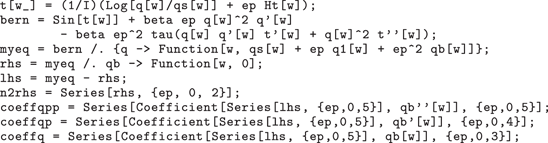
Mathematica code to generate the reduced model. Functions are written q for  $q$, qb for
 $\bar{q}$ and t for
 $\unicode[STIX]{x1D703}$. Parameters are written ep for
 $\unicode[STIX]{x1D716}$, tau for
 $\unicode[STIX]{x1D70F}$ and beta for
 $\unicode[STIX]{x1D6FD}$. The Hilbert transform is represented by Ht[w], and to ensure that the asymptotics are done correctly we make the size of the remainder term explicit by writing
 $\unicode[STIX]{x1D716}^{2}\bar{q}$ in place of
 $\bar{q}$.

A.2 Derivation of the $N=2$ model

The reduced model used for the numerical results in § 6 is obtained by truncating the base series after  $N=2$ terms. Using the substitution (5.3), to leading order in
 $\unicode[STIX]{x1D716}$ the complex governing equations (5.1) become
 $$\begin{eqnarray}\displaystyle \left.\begin{array}{@{}c@{}}\sin (\unicode[STIX]{x1D703}_{0})=0,\\ \log q_{0}-\text{i}\unicode[STIX]{x1D703}_{0}+\hat{\mathscr{H}}[\unicode[STIX]{x1D703}_{0}]-\log q_{s}=0,\end{array}\right\} & & \displaystyle\end{eqnarray}$$
whence  $\unicode[STIX]{x1D703}_{0}=0$ and
 $q_{0}=q_{s}$. At the next order,
 $$\begin{eqnarray}\displaystyle \left.\begin{array}{@{}c@{}}\unicode[STIX]{x1D6FD}q_{s}^{2}q_{s}^{\prime }+\unicode[STIX]{x1D703}_{1}=0,\\[5.0pt] {\displaystyle \frac{q_{1}}{q_{s}}}-\text{i}\unicode[STIX]{x1D703}_{1}+\hat{\mathscr{H}}[\unicode[STIX]{x1D703}_{1}]=0,\end{array}\right\} & & \displaystyle\end{eqnarray}$$
which gives  $\unicode[STIX]{x1D703}_{1}$ and
 $q_{1}$ as in (5.6c) and (5.6d).
To derive the reduced model, we then substitute
 $$\begin{eqnarray}\unicode[STIX]{x1D703}=-\text{i}(\log (q/q_{s})+\hat{\mathscr{H}}[\unicode[STIX]{x1D703}])\end{eqnarray}$$
into (5.1a) and expand in powers of  $\unicode[STIX]{x1D716}$, with the base series known. By construction, the leading-order forcing term is
 $O(\unicode[STIX]{x1D716}^{2})$. The coefficients of
 $\bar{q}$ and its derivatives are also expanded in powers of
 $\unicode[STIX]{x1D716}$, and the number of terms retained reflects the ansatz (5.5), which indicates that every derivative of
 $\bar{q}$ contributes a factor of
 $1/\unicode[STIX]{x1D716}$. For ease of use, we show in table 1 how the reduced model can be derived in the coding language Mathematica.