1. Introduction
The flow past bluff bodies has attracted the attention of many scholars for decades (Braza, Chassaing & Minh Reference Braza, Chassaing and Ha Minh1986; Schumm, Berger & Monkewitz Reference Schumm, Berger and Monkewitz1994; Saiki & Biringen Reference Saiki and Biringen1996; Williamson et al. Reference Williamson, Gavrilakis, Machiels and Monkewitz1996; Sohankar, Norberg & Davidson Reference Sohankar, Norberg and Davidson1998; Kumar & Mittal Reference Kumar and Mittal2006; Pralits, Brandt & Giannetti Reference Pralits, Brandt and Giannetti2010; Jiang & Cheng Reference Jiang and Cheng2018), because of its relevance, that goes beyond a fundamental interest to encompass industrial applications, especially in the field of vortex-induced oscillations (Williamson & Govardhan Reference Williamson and Govardhan2008). The pressure and friction distributions produce net forces on the body. With the onset of the first two-dimensional instability, i.e. the primary instability, pressure and friction start fluctuating, due to the vortex shedding. Since large fluctuations may cause acoustic noise and structural damages, understanding the instability of such flows is of interest for the fluid mechanics community, driven by the goal of controlling it.
The circular cylinder is the natural prototype of a bluff body, owing to its simple geometry, and it has been extensively investigated (see e.g. Zdravkovich Reference Zdravkovich1997). At a critical Reynolds number of  $\textit {Re}_c \approx 47$ the flow undergoes a Hopf bifurcation from a symmetric steady state towards a time-periodic non-symmetric state (Provansal, Mathis & Boyer Reference Provansal, Mathis and Boyer1987; Sreenivasan, Strykowski & Olinger Reference Sreenivasan, Strykowski and Olinger1987; Noack & Eckelmann Reference Noack and Eckelmann1994). While a global instability has been found to be responsible for the onset of the vortex shedding (Jackson Reference Jackson1987), a complete understanding of the physical mechanism is still lacking. In this respect, an important theoretical advancement has been the concept of the wave maker (Monkewitz, Huerre & Chomaz Reference Monkewitz, Huerre and Chomaz1993). In particular, when the interest lies in damping the global instability, it is important to identify the so-called wave-maker region, i.e. the region in the flow where the instability mechanism acts to produce the self-sustained oscillations. Giannetti & Luchini (Reference Giannetti and Luchini2007) first proposed the structural sensitivity as a way to locate the wave maker in a global instability. They applied it to the two-dimensional flow around a circular cylinder, showing that the wave-maker region is characterised by two lobes symmetrically placed across the separation bubble, i.e. the closed region delimited by two streamlines separating from the body surface. Active and passive control techniques have been tested to control vortex shedding past a circular cylinder. For passive control, Strykowski & Sreenivasan (Reference Strykowski and Sreenivasan1990) have experimentally shown that a small control cylinder delays the onset of the primary instability when correctly placed within the flow. Similar results were then obtained numerically by Mittal & Raghuvanshi (Reference Mittal and Raghuvanshi2001) via direct numerical simulations, and by Morzyński, Afanasiev & Thiele (Reference Morzyński, Afanasiev and Thiele1999) via linear stability analysis. Marquet, Sipp & Jacquin (Reference Marquet, Sipp and Jacquin2008) provided the theoretical framework to explain the modification of the vortex shedding observed experimentally. They introduced the concepts of sensitivity to base-flow modification and sensitivity to a steady force, which quantify how a perturbation of the base flow and a steady force alter the onset of the primary instability, the results for the circular cylinder being in good agreement with experiments.
The rectangular cylinder has received less attention than its circular counterpart. Nevertheless, the study of rectangular cylinders is of great interest from the point of view of applications, as many structures, such as buildings, bridges, pylons, typically have rectangular or nearly rectangular cross-sections (Tamura, Miyagi & Kitagishi Reference Tamura, Miyagi and Kitagishi1998). Despite the simple geometry, the problem is interesting from a fundamental viewpoint too. Indeed, the flow around rectangular cylinders presents peculiar features that characterise flows around bodies of more complex shape: corner-induced separations, shear layer instability, recirculating flow regions and an unstable wake (see e.g. Almeida, Mansur & Silveira-Neto (Reference Almeida, Mansur and Silveira-Neto2008), and the references therein). Depending on its aspect ratio  $AR$ (the ratio between the streamwise length
 $L$ and the cross-stream dimension
 $D$ of the body), a rectangular cylinder spans a whole range of bluff blunt bodies, from a flat plate placed normal to the flow (
 $AR=0$) to a square cylinder (
 $AR=1$) and, finally, to a flat plate parallel to the flow (
 $AR \rightarrow \infty$). Features of the cross-flow, pressure and friction distributions bear a significant dependence upon the aspect ratio. For intermediate Reynolds numbers, i.e.
 $Re \approx 300\text {--}400$, the main features and their dependence on
 $AR$ have been thoroughly investigated. For small
 $AR$, i.e.
 $AR<2$, the flow does not reattach after the separation at the leading edge (LE), and vortex shedding only occurs at the LE. For intermediate
 $AR$, i.e.
 $2 \leqslant AR \leqslant 3$, an intermittent reattachment on the longitudinal side takes place. For larger
 $AR$, the flow reattaches permanently, and eventually separates again at the trailing edge (TE). For these
 $AR$, vortex shedding occurs from the shear layers at both the LE and TE. The phenomenon has a unique frequency, since the two shedding processes are interlocked as a result of the impinging shear-layer instability that interacts with the TE vortex shedding (Nakamura & Nakashima Reference Nakamura and Nakashima1986; Hourigan et al. Reference Hourigan, Mills, Thompson, Sheridan, Dilin and Welsh1993; Hourigan, Thompson & Tan Reference Hourigan, Thompson and Tan2001; Mills, Sheridan & Hourigan Reference Mills, Sheridan and Hourigan2002, Reference Mills, Sheridan and Hourigan2003). This interlocking mechanism leads to a stepwise dependence on
 $AR$ of the Strouhal number based on the cylinder longitudinal length; it has been observed by several authors both numerically and experimentally for Reynolds numbers up to
 $2000$ (Okajima Reference Okajima1982; Nakamura & Nakashima Reference Nakamura and Nakashima1986; Ozono et al. Reference Ozono, Ohya, Nakamura and Nakayama1992; Tan, Thompson & Hourigan Reference Tan, Thompson and Hourigan1998). Similarly, several works have studied the three-dimensional instability of this flow. Robichaux, Balachandar & Vanka (Reference Robichaux, Balachandar and Vanka1999), Blackburn & Lopez (Reference Blackburn and Lopez2003), Sheard, Fitzgerald & Ryan (Reference Sheard, Fitzgerald and Ryan2009), Blackburn & Sheard (Reference Blackburn and Sheard2010) and others investigated the wake instability behind a square cylinder via Floquet stability analysis, observing a quasi-periodic unstable mode that has been found also in the wake of a circular cylinder (Blackburn, Marques & Lopez Reference Blackburn, Marques and Lopez2005). The effect of
 $AR$ was also assessed: for example, we mention the works by Choi & Yang (Reference Choi and Yang2014) and Jiang & Cheng (Reference Jiang and Cheng2018), who studied the three-dimensional instability from the limit
 $AR \rightarrow 0$ (corresponding to a flat plate normal to the flow) to
 $AR=1$ via Floquet analysis and direct numerical simulations, and that by Hourigan et al. (Reference Hourigan, Thompson and Tan2001), who investigated the three-dimensional patterns in the boundary layer along rectangular cylinders with
 $AR$ up to
 $13$. However, for the low Reynolds number associated with the primary two-dimensional instability, to the best of the authors’ knowledge, a comprehensive study encompassing the whole range of
 $AR$ is still missing. Indeed, all the studies at such low Reynolds number focus on the square cylinder. For this aspect ratio,
 $AR=1$, the onset of the primary instability closely resembles the one for the circular cylinder with the flow undergoing a Hopf bifurcation, but occurs at a lower Reynolds number, even though the reported data are scattered according to Jiang & Cheng (Reference Jiang and Cheng2018), who themselves measure
 $\textit {Re}_c=46$. For example, Sohankar, Norberg & Davidson (Reference Sohankar, Norberg and Davidson1999) report
 $\textit {Re}_c=47 \pm 2$, Saha, Muralidhar & Biswas (Reference Saha, Muralidhar and Biswas2000) set it at
 $\textit {Re}_c=45$ and Park & Yang (Reference Park and Yang2016) mention
 $\textit {Re}_c = 44.7$.
It should be mentioned that perfectly sharp corners are just an idealisation, since the corners of real bodies are always rounded to some extent. It is known that rounding the corners of bluff bodies can significantly impact the flow properties (Park & Yang Reference Park and Yang2016; Cimarelli, Franciolini & Crivellini Reference Cimarelli, Franciolini and Crivellini2020; Rocchio, Mariotti & Salvetti Reference Rocchio, Mariotti and Salvetti2020). For rounded corners, despite the number of studies assessing the large-Reynolds number case (see for e.g. Lamballais, Silvestrini & Laizet Reference Lamballais, Silvestrini and Laizet2008, Reference Lamballais, Silvestrini and Laizet2010; Cao & Tamura Reference Cao and Tamura2017), few works have considered the dependence of the onset of the instabilities on the corner curvature. Park & Yang (Reference Park and Yang2016) determined, via linear stability analysis, how the primary two-dimensional and the three-dimensional instabilities are affected by rounding the four corners of a rectangular cylinder with  $AR=1$, exploring the shapes ranging between the square cylinder with sharp edges and the circular cylinder. They observed that the primary instability onset changes with corner curvature, finding that
 $\textit {Re}_c$ does not change monotonically with the curvature and that the most stable configuration is an intermediate configuration between the circular and the square cylinder. For the three-dimensional instability, instead, they found noticeable changes in terms of both unstable modes and the range of unstable spanwise wavelengths.
The aim of the present numerical study is to provide a comprehensive overview of the primary two-dimensional instability past rectangular cylinders in a wide range of  $AR$. Both sharp and/or rounded corners are considered, with
 $0.25 \leqslant AR \leqslant 30$. The onset of the primary instability is addressed, and the unstable modes and wave-maker regions are identified. Sensitivity to either base-flow modifications or steady forces are evaluated to assess how the onset of the instability can be delayed via suitable placement of a small control cylinder. The paper is organised as follows. After this introduction, a brief description of the mathematical formulation and of the numerical method adopted is presented in § 2. Section 3 studies the rectangular cylinders with sharp corners in terms of primary instability and structural sensitivities. In § 4 the dependence of the primary instability on the rounding of the LE and/or TE corners is addressed. Concluding remarks are drawn in § 5.
2. Mathematical formulation
2.1. Flow configuration
The incompressible flow over two-dimensional, rectangular cylinders with aspect ratio  $0.25 \leqslant AR \leqslant 30$ is considered. Figure 1 shows the geometry, the reference system and the notation. A Cartesian coordinate system is used, with origin at the LE of the cylinder, with the
 $x$ axis being the symmetry axis aligned with the free-stream direction, and the
 $y$ axis denoting the cross-stream direction. The cylinder has length
 $L$ and cross-stream size
 $D$, and is placed in a uniform flow with velocity
 $U_\infty$. The computational domain has dimensions
 $L_x$ and
 $L_y$. The Reynolds number is
 $\textit {Re}=U_\infty D/\nu$. The flow is governed by the incompressible Navier–Stokes equations,
 \begin{equation} \left.\begin{gathered} \frac{\partial \boldsymbol{u}}{\partial t} + \boldsymbol{u} \boldsymbol{\cdot} \boldsymbol{\nabla}\boldsymbol{u} ={-} \boldsymbol{\nabla}p + \frac{1}{\textit{Re}}\Delta \boldsymbol{u}+ \boldsymbol{F}, \\ \boldsymbol{\nabla} \boldsymbol{\cdot} \boldsymbol{u} =0, \end{gathered}\right\}\end{equation}
where  $\boldsymbol {F}$ denotes a volume forcing.
Sketch of the computational domain with the geometry of the rectangular cylinder.

2.2. Modal stability analysis
The onset of the instability is classically studied in linear theory by using a normal-mode analysis (Theofilis Reference Theofilis2003, Reference Theofilis2011). The field  $\{\boldsymbol {u},p\}$ of velocity and pressure is decomposed into the sum of a time-independent base flow
 $\{\boldsymbol {U},P\}$ and an unsteady contribution
 $\{\boldsymbol {u'},p'\}$ with small amplitude
 $\epsilon$, as
 \begin{equation} \boldsymbol{u}(\boldsymbol{x},t) = \boldsymbol{U}(\boldsymbol{x}) + \epsilon \boldsymbol{u}'(\boldsymbol{x},t), \quad p(\boldsymbol{x},t) = P(\boldsymbol{x}) + \epsilon p'(\boldsymbol{x},t). \end{equation}
Using this decomposition in the Navier–Stokes equations (2.1), separate equations for the spatial structure of the base flow and the temporal evolution of the perturbation are obtained. The base flow is governed by the steady version of (2.1), whereas the perturbation field is described by the linearised unsteady Navier–Stokes equation (LNSE),
 \begin{equation} \left.\begin{gathered} \frac{\partial \boldsymbol{u}'}{\partial t} + \boldsymbol{\mathsf{L}}\{\boldsymbol{U},\textit{Re}\} \boldsymbol{u}' ={-}\boldsymbol{\nabla} p', \\ \boldsymbol{\nabla} \boldsymbol{\cdot} \boldsymbol{u}' = 0, \end{gathered}\right\} \end{equation}
where  $\boldsymbol{\mathsf{L}}$ stands for the linearised Navier–Stokes operator,
 \begin{equation} {{L}}\{\boldsymbol{U},{Re}\}\boldsymbol{u}'=\boldsymbol{U} \boldsymbol{\cdot} \boldsymbol{\nabla} \boldsymbol{u}' + \boldsymbol{u}' \boldsymbol{\cdot} \boldsymbol{\nabla} \boldsymbol{U} - \frac{1}{{Re}} \Delta \boldsymbol{u}'. \end{equation}
The differential problem (2.3) is completed by initial and boundary conditions. The perturbation velocity field is set to zero on the boundary of the computational domain, except at the outlet boundary, where outflow boundary conditions
 \begin{equation} p' \boldsymbol{n} - Re^{{-}1} \boldsymbol{\nabla} \boldsymbol{u}' \boldsymbol{\cdot} \boldsymbol{n}=0 \end{equation}
are used, where  $\boldsymbol {n}$ is the normal vector.
We are interested in the global modes of the linearised Navier–Stokes equations, i.e. non-trivial solutions of the system (2.3) of the form
 \begin{equation} \boldsymbol{u}'(\boldsymbol{x},t)=\hat{\boldsymbol{u}}(\boldsymbol{x})\textrm{e}^{\lambda t}, \quad p'(\boldsymbol{x},t) = \hat{p}(\boldsymbol{x})\textrm{e}^{\lambda t}. \end{equation}
Here  $\lambda$ is a complex number, while the complex field
 $\{\hat {\boldsymbol {u}},\hat {p}\}$ satisfies
 \begin{equation} \left.\begin{gathered} \lambda \hat{\boldsymbol{u}} + \boldsymbol{\mathsf{L}}\{\boldsymbol{U},\textit{Re}\} \hat{\boldsymbol{u}} + \boldsymbol{\nabla}\hat{p}=0, \\ \boldsymbol{\nabla} \boldsymbol{\cdot} \hat{\boldsymbol{u}}=0. \end{gathered}\right\} \end{equation}
Solving the generalised eigenvalue problem for the complex frequency  $\lambda$ leads one to ascertain the flow stability, which requires all the eigenvalues to have negative real part.
2.3. Structural sensitivity
A better understanding of the instability mechanisms can be obtained thanks to the structural sensitivity, a concept introduced by Giannetti & Luchini (Reference Giannetti and Luchini2007) for the primary instability and then extended by Giannetti, Camarri & Luchini (Reference Giannetti, Camarri and Luchini2010) to the secondary instability. Structural sensitivity is based on the interplay between direct and adjoint modes.
The adjoint LNSE (see for e.g. Giannetti & Luchini Reference Giannetti and Luchini2007) are
 \begin{equation} \left.\begin{gathered} -\frac{\partial \boldsymbol{f}^+}{\partial t} + \boldsymbol{\mathsf{L}}^+ \{\boldsymbol{U}, \textit{Re} \} \boldsymbol{f}^+{-} \boldsymbol{\nabla} m^+{=}0, \\ \boldsymbol{\nabla} \boldsymbol{\cdot} \boldsymbol{f}^+{=} 0, \end{gathered}\right\} \end{equation}
where  $\boldsymbol{\mathsf{L}}^+ \{\boldsymbol {U}, \textit {Re} \}$ is the adjoint of the linearised Navier–Stokes operator,
 \begin{equation} \boldsymbol{\mathsf{L}}^+ \{\boldsymbol{U}, \textit{Re} \} \boldsymbol{f}^+{=} - \left( \boldsymbol{U} \boldsymbol{\cdot} \boldsymbol{\nabla} \right) \boldsymbol{f}^+{+} \left(\boldsymbol{\nabla} \boldsymbol{U} \right) \boldsymbol{\cdot} \boldsymbol{f}^+{-} \frac{1}{\textit{Re}} \nabla^2 \boldsymbol{f}^+. \end{equation}
The solution of the adjoint equations can be useful to study the receptivity of the modes to an external forcing, as the receptivity of a mode to a periodic forcing in the momentum and/or continuity equation is proportional to the local magnitude of the adjoint fields  $\boldsymbol {f}^+$ and
 $m^+$.
Since our interest lies in the primary instability of the flow, we will seek non-trivial solutions of the adjoint LNSEs (2.8) of the form
 \begin{equation} \boldsymbol{f}^+(\boldsymbol{x},t) = \hat{\boldsymbol{f}}^+(\boldsymbol{x})\textrm{e}^{-\lambda t}, \quad m^+(\boldsymbol{x},t) = \hat{m}^+(\boldsymbol{x})\textrm{e}^{-\lambda t}. \end{equation}
If  $\{ \hat {\boldsymbol {u}}(\boldsymbol {x})\textrm {e}^{\lambda t}, \hat {p}(\boldsymbol {x})\textrm {e}^{\lambda t} \}$ is a global mode of the LNSE corresponding to the eigenvalue
 $\lambda$,
 $\{ \hat {\boldsymbol {f}}^+ (\boldsymbol {x})\textrm {e}^{-\lambda t}, \hat {m}^+(\boldsymbol {x}) \textrm {e}^{-\lambda t} \}$ is the non-trivial solution of the adjoint LNSEs corresponding to the same eigenvalue.
With direct and adjoint perturbation modes available, one knows the spatial location of the largest perturbation amplitude and of the largest receptivity. These two pieces of information are brought together by computing the structural sensitivity  $S$, which identifies the region where the instability mechanisms is at work. After defining the employed inner product of two complex vector fields
 $\boldsymbol {u}_A$ and
 $\boldsymbol {u}_B$ as the inner product of
 $L^2(D)$:
 $(\boldsymbol {u}_A,\boldsymbol {u}_B) = \int _{D} (\boldsymbol {u}_A^* \boldsymbol {\cdot } \boldsymbol {u}_B ) \,\textrm {d} \varOmega$, with
 $^*$ denoting the complex conjugate,
 $S$ is defined by Giannetti & Luchini (Reference Giannetti and Luchini2007) as
 \begin{equation} S(\boldsymbol{x})=\frac{ \| \hat{\boldsymbol{f}}^+(\boldsymbol{x}) \| \ \| \hat{\boldsymbol{u}}^+(\boldsymbol{x}) \|}{(\hat{\boldsymbol{f}}^+, \hat{\boldsymbol{u}})}, \end{equation}
where  $\| . \|$ represents the usual
 $\mathbb {R}^2$ vector norm. Large values of
 $S$ identify the region of the flow where disturbance amplification and receptivity combine at their best to trigger the instability.
2.4. Sensitivity to base-flow modifications and to steady forces
A small variation  $\delta \boldsymbol {U}$ of the base flow leads to a variation of the complex eigenpairs
 $(\sigma , \hat {\boldsymbol {u}}, \hat {p})$, as discussed for the circular cylinder by Marquet et al. (Reference Marquet, Sipp and Jacquin2008). The variation of the eigenvalues,
 $\delta \sigma$, and the perturbation of the base flow,
 $\delta \boldsymbol {U}$, are linked by the following inner product:
 \begin{equation} \delta \sigma= (\boldsymbol{\nabla}_{\boldsymbol{U}} \sigma, \delta \boldsymbol{U}), \end{equation}
where  $\boldsymbol {\nabla }_{\boldsymbol {U}} \sigma$ denotes the sensitivity of
 $\sigma$ to base-flow modifications. Similarly, variations of the growth rate
 $\delta \lambda$ and frequency
 $\delta \omega$ may be expressed as
 \begin{equation} \delta \lambda = ( \boldsymbol{\nabla}_{\boldsymbol{U}} \lambda, \delta \boldsymbol{U} ), \quad \delta \omega = ( \boldsymbol{\nabla}_{\boldsymbol{U}} \omega , \delta \boldsymbol{U} ), \end{equation}
where  $\boldsymbol {\nabla }_{\boldsymbol {U}} \lambda$ and
 $\boldsymbol {\nabla }_{\boldsymbol {U}} \omega$ denote the corresponding sensitivities:
 \begin{equation} \boldsymbol{\nabla}_{\boldsymbol{U}} \lambda = \text{Re} \{ \boldsymbol{\nabla}_{\boldsymbol{U}} \sigma \}, \quad \boldsymbol{\nabla}_{\boldsymbol{U}} \omega ={-}\text{Im} \{ \boldsymbol{\nabla}_{\boldsymbol{U}} \sigma \}. \end{equation}
As described by Marquet et al. (Reference Marquet, Sipp and Jacquin2008),  $\boldsymbol {\nabla }_{\boldsymbol {U}} \sigma$ is linked with the direct and adjoint eigenmodes by
 \begin{equation} \boldsymbol{\nabla}_{\boldsymbol{U}} \sigma = \frac{- ( \boldsymbol{\nabla} \hat{\boldsymbol{u}} )^H \boldsymbol{\cdot} \hat{\boldsymbol{f}}^+{+} \boldsymbol{\nabla} \hat{\boldsymbol{f}}^+ \boldsymbol{\cdot} \hat{\boldsymbol{u}}^*}{\displaystyle\int_{\varOmega} \hat{\boldsymbol{u}}^* \boldsymbol{\cdot} \hat{\boldsymbol{f}}^+ \textrm{d} \varOmega}, \end{equation}
where the superscript  $^H$ designates the transconjugate.
Once again, large values of  $|\boldsymbol {\nabla }_{\boldsymbol {U}} \lambda |$ and
 $|\boldsymbol {\nabla }_{\boldsymbol {U}} \omega |$ identify regions in the flow where
 $\lambda$ or
 $\omega$ are most sensitive to a modification
 $\delta \boldsymbol {U}$ of the base flow. Unlike the sensitivity
 $S$, these quantities are vector fields, therefore providing directional information too.
Analogously, an eigenvalue  $\sigma$ may be viewed as a function of a steady force
 $\boldsymbol {F}$. A small variation
 $\delta \boldsymbol {F}$ of the steady force
 $\boldsymbol {F}$ induces a variation
 $\delta \boldsymbol {U}$ of the base flow. The variation
 $\delta \sigma$ can be linked to
 $\delta \boldsymbol {F}$ via
 \begin{equation} \delta \sigma = (\boldsymbol{\nabla}_{\boldsymbol{F}} \sigma, \delta \boldsymbol{F} ), \end{equation}
where  $\boldsymbol {\nabla }_{\boldsymbol {F}} \sigma$ is the sensitivity to a modification of the steady force and, as before,
 \begin{equation} \boldsymbol{\nabla}_{\boldsymbol{F}} \lambda = \text{Re} \{ \boldsymbol{\nabla}_{\boldsymbol{F}} \sigma \}, \quad \boldsymbol{\nabla}_{\boldsymbol{F}} \omega ={-}\text{Im} \{ \boldsymbol{\nabla}_{\boldsymbol{F}} \sigma \}. \end{equation}
Marquet et al. (Reference Marquet, Sipp and Jacquin2008) demonstrate that  $\boldsymbol {\nabla }_{\boldsymbol {F}} \sigma$ equals the adjoint base-flow velocity.
2.5. Numerical details
The base flow is obtained by solving the two-dimensional version of the steady Navier–Stokes equations (2.1) using the Newton algorithm. The spatial discretisation is based on a finite-element formulation using quadratic elements ( $P2$) for the velocity and linear elements (
 $P1$) for the pressure. This numerical method is implemented in the non-commercial software FreeFem
 $++$ (Hecht Reference Hecht2012). A symmetric mesh with respect to the
 $x$ axis has been used for all the configurations to avoid introducing asymmetries in the flow. The size and the spatial distribution of the triangles has been chosen to properly refine the mesh around the cylinders and in the wake. The number of triangles changes with the mesh and therefore with
 $AR$, and ranges from a minimum of approximately
 $40 \times 10^3$ to a maximum of
 $60 \times 10^3$. The eigenvalue problem (2.7) is then solved with the Arnoldi iterative algorithm by calling the ARPACK package (Lehoucq, Sorensen & Yang Reference Lehoucq, Sorensen and Yang1998). When a single eigenvalue is required, a simple shift-and-invert method (Saad Reference Saad2011) is used.
The computational domain used in the present analysis changes with the aspect ratio of the rectangular cylinders. For  $AR \leqslant 5$ the domain extends for
 $-25D \leqslant x \leqslant 50D$ in the streamwise direction and for
 $-20 D \leqslant y \leqslant 20D$ in the cross-stream direction corresponding to a size of
 $(L_x,L_y)=(75D,40D)$, whereas for larger
 $AR$ it is enlarged up to
 $(L_x,L_y)=(100D,60D)$ extending from
 $-25D \leqslant x \leqslant 75D$ and
 $-30D \leqslant y \leqslant 30D$ in the two directions; the rectangular cylinder is placed at
 $0 \leqslant x \leqslant L$ and
 $-D/2 \leqslant y \leqslant D/2$.
We have validated the results by varying both the grid resolution and the domain size. The tests reported in the Appendix (A) confirm the reliability of the present results.
3. Rectangular cylinders with sharp corners
3.1. Base flow
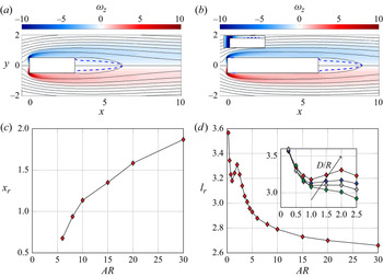
The base flows are very similar over the whole range of considered  $AR$. In figure 2, the spatial distribution of the vorticity
 $\omega _z= \partial V / \partial x - \partial U / \partial y$ is plotted, which is antisymmetric with respect to the centreline
 $y=0$, and presents its largest values near the upstream corners of the cylinder. As an example, the base flows for
 $AR=3$ and
 $AR=6$ are shown in figure 2 at a Reynolds number corresponding to the first onset of the instability, i.e.
 $\textit {Re}=78.3$ and
 $\textit {Re}=107.6$, as discussed later. In both cases, two shear layers detach from the corners, one on the upper side, and one on the lower side, with vorticity of opposite sign. These shear layers delimit a symmetric separation bubble after the body tail. However, for the larger
 $AR=6$, a second, smaller recirculation bubble appears just downstream of the LE of the cylinder: the separated flow reattaches on the cylinder walls, before separating again at the TE. As indicated in figure 2(c), the secondary bubble only appears for
 $AR \geqslant 6$, and its size increases with
 $AR$. In contrast, the length of the main separation bubble downstream of the TE does not depend monotonically on
 $AR$. Indeed, as shown in figure 2(d), the length generally decreases with
 $AR$ but presents a localised increase in the range
 $1 \leqslant AR \leqslant 2$.
(a,b) Base flow for  $AR=3$ at
 $\textit {Re}=78.31$ (a) and for
 $AR=6$ at
 $\textit {Re}=107.6$, with the zoom on the upstream separated region in the inset in panel (b). Streamlines are shown on top of a vorticity map; the dashed line denotes
 $U=0$. (c,d) Streamwise coordinate
 $x_r$ of the reattachment point (c) and length
 $l_r$ of the main recirculating bubble (d) as a function of
 $AR$, measured at the Reynolds number corresponding to the first onset of the instability. The inset in panel (d) shows a zoom of
 $l_r$ for
 $0.25 \leqslant AR \leqslant 2.5$; the different lines highlight the effect of rounding the TE corner: they refer to the sharp configuration (red),
 $D/R=8$ (blue),
 $D/R=4$ (grey) and
 $D/R=2$ (green), respectively, where
 $R$ is the radius of curvature of the rounded corner.

3.2. Global modes
The global stability of the base flow is studied by looking for the leading global mode  $\{\hat {\boldsymbol {u}},\hat {p}\}$, i.e. the global mode with the largest growth rate
 $\lambda$. Figure 3(a) plots the evolution with
 $AR$ of the critical Reynolds number
 $\textit {Re}_c$ of the primary instability, i.e. the Reynolds number at which the growth rate crosses the real axis; Figure 3(b) plots the corresponding frequency
 $f_s =\omega / 2 {\rm \pi}$. Numerical values are also reported in table 1.
Effect of  $AR$ on the primary instability. (a) Dependence of
 $\textit {Re}_c$ and
 $\widehat {\textit {Re}}_c = ( |U_{{min}}| l_r / \nu )_c$ on
 $AR$. The dependence of
 $f_s$ on
 $AR$ is shown in panel (b) with an inset showing a close-up. Panel (c) shows the
 $\lambda (\textit {Re})$ curve for
 $AR=1,2,3,4,5$.

Critical Reynolds number  $\textit {Re}_c$ of the primary instability and corresponding frequency
 $f_s$ for rectangular cylinders with
 $0.25 \leqslant AR \leqslant 30$.

For  $AR=1$, the flow is stable at
 $\textit {Re}=44.5$ and unstable at
 $\textit {Re}=44.6$, with
 $\textit {Re}_c = 44.56$ resulting by linear interpolation to obtain
 $\lambda =0$. This is in good agreement with existing results for the square cylinder. Yoon, Yang & Choi (Reference Yoon, Yang and Choi2010) and Saha et al. (Reference Saha, Muralidhar and Biswas2000) found
 $\textit {Re}_c=45$, Sohankar et al. (Reference Sohankar, Norberg and Davidson1998) determine
 $\textit {Re}_c=47 \pm 2$, Park & Yang (Reference Park and Yang2016) with
 $\textit {Re}_c=44.7$ and Jiang & Cheng (Reference Jiang and Cheng2018) report
 $\textit {Re}_c=46$. Moreover, figure 3(a) shows that increasing
 $AR$ immediately leads to a more stable flow, i.e. a flow with larger
 $\textit {Re}_c$. The increase of
 $\textit {Re}_c$ with
 $AR$ is quick at first, but the sensitivity of
 $\textit {Re}_c$ to
 $AR$ decreases as
 $AR$ is increased. The frequency
 $f_s$ does not show a monotonic trend: it generally decreases with
 $AR$, but it increases for
 $1 \leqslant AR \leqslant 3.5$, hence presenting a local minimum at
 $AR=1$ and the absolute maximum at
 $AR=3.5$. The dependence of
 $f_s$ on
 $AR$ recalls that of the size of the main recirculating bubble (see figure 2d) only incidentally, since the change in slope occurs for different
 $AR$ in the two cases. Additional information is found in figure 3(c), where the growth rate
 $\lambda$ is plotted as a function of the Reynolds number for
 $AR=1,2,3,4,5$. The slope of the curve
 $\lambda (\textit {Re})$ decreases by increasing
 $AR$, including when
 $\textit {Re} \rightarrow \textit {Re}_c$. This implies that, as
 $AR$ is increased, the rectangular cylinder becomes less sensitive to a variation of the Reynolds number, as long as the primary instability is considered.
The increase of  $\textit {Re}_c$ with
 $AR$ is associated with the progressive diffusion of the shear layers that separate from the LE corners. Indeed, owing to viscous diffusion, the two shear layers that produce the instability become thicker in the instability region as
 $AR$ is increased, since the pockets of instability positioned on the two sides of the separation bubble move downstream with respect to the LE where the shear layers are produced, as reported later in this article. This is confirmed by a progressive reduction of the minimum reverse-flow speed within the separation bubble. Since the reverse-flow speed has a strong impact on the growth rate of the unstable mode (Hammond & Redekopp Reference Hammond and Redekopp1997), the instability mechanism becomes less intense as
 $AR$ increases, and the critical Reynolds number progressively increases. For
 $AR>2$, the same phenomenon (i.e. the increasing diffusion of the separated shear layers) is responsible for a reduction of the length of the separation bubble, see figure 2(d). The non-monotonic behaviour of
 $l_r$ comes from the interaction of the fore region of the shear layer separating from the LE with the aft corners for low
 $AR$. By plotting the pressure over a line slightly above or below the rectangle, a negative pressure peak is visible in the position of the aft corners (not shown here for brevity). For
 $AR < 2$ the pressure peak interacts with the fore portion of the shear layer which faces a strong adverse pressure gradient, while for
 $AR>2$ it interacts with the aft part of the shear layer. This hypothesis is confirmed by the fact that rounding the TE corners progressively eliminates the non-monotonic behaviour, as shown in the inset of figure 2(d). The minimum speed in the recirculation bubble and its length are the most important scales in the instability phenomenon. The former directly impacts the local amplification of the unstable wave packets, while the second one dictates the spatial extent of the absolute instability (Chomaz Reference Chomaz2005), thus affecting the global stability of the flow. This observation is confirmed by considering the Reynolds number defined as
 $\widehat {\textit {Re}}=|U_{{min}}| l_r/\nu$ and plotting its critical value
 $\widehat {\textit {Re}}_c(AR)$. Figure 3(a) shows that the relative variation of
 $\widehat {\textit {Re}}_c(AR)$ is smaller by an order of magnitude with respect to that of
 $\textit {Re}_c(AR)$. This scaling is not perfect, as
 $\widehat {\textit {Re}}_c$ should be ideally constant with
 $AR$ in this case, but is far more accurate than that based on the cylinder thickness
 $D$ and on the free stream velocity
 $U_{\infty }$. For sufficiently large
 $AR$, the same phenomenon leads the frequency of the instability to decrease, as observed in figure 3(b), since the length scale of the instability increases and the flow speed decreases. The non-monotonic behaviour observed for small
 $AR$, however, seems not related to the interaction of the main shear layers with the TE corners, since it is insensitive to rounding the TE corners; its origin remains elusive.
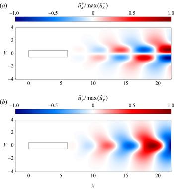
The spatial shape of the leading unstable global mode remains qualitatively similar across the considered aspect ratios. In figure 4 the mode computed for  $AR=6$ and
 $\textit {Re}=\textit {Re}_c=107.5$ is shown as an example. For all the considered
 $AR$, the leading global mode propagates downstream and is antisymmetric, as for the circular cylinder (Marquet et al. Reference Marquet, Sipp and Jacquin2008). The
 $y$-averaged perturbation energy grows spatially downstream, reaching a maximum, for example, at
 $x \sim 38,48,48,49$ for
 $AR=1,2,3,5$, respectively. Although the position of the maximum approaches the outlet for
 $AR=3,5$, the results are independent from the length of the computational domain, as shown in the Appendix (A) where the independence of the results on both the grid resolution and domain size for
 $AR=5$ is demonstrated; see also Giannetti & Luchini (Reference Giannetti and Luchini2007), where the dependence of the leading global mode on the domain length is investigated.
Real part of the direct eigenmode for  $AR=6$ and
 $\textit {Re}=107.5$.

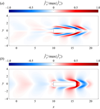
The adjoint ( $\hat {\boldsymbol {f}}^+,m^+$) of the leading global mode for
 $AR=6$ and
 $\textit {Re}=107.5$ is shown in figure 5. Like the direct modes, the adjoint modes are antisymmetric. They show spatial oscillations upstream of the rectangular cylinder; the same was observed for the adjoint modes for the circular cylinder (Marquet et al. Reference Marquet, Sipp and Jacquin2008). Unlike
 $\hat {\boldsymbol {u}}$, the largest magnitude of
 $\hat {\boldsymbol {f}}^+$ is reached very close to the downstream corners, for example at
 $(x,y) = (1.05,0,6), (2.02,0.6), (3.07,0.6), (5.03,0.6)$ for
 $AR=1,2,3,5$, and it is almost null at a distance downstream from TE which depends on
 $AR$ (e.g. for
 $AR=6$,
 $\hat {\boldsymbol {f}}^+$ is negligible for
 $x > 10$ as shown in figure 5). The different localisation of the direct and adjoint global modes (downstream for the former and upstream for the latter) results from the opposite transport of perturbations by the base flow in the direct and adjoint operators (Chomaz Reference Chomaz2005).
Real part of the adjoint eigenmode for  $AR=6$ and
 $\textit {Re}=107.5$.

3.3. Structural sensitivity
Figure 6 shows the structural sensitivity  $S$ for rectangular cylinders with
 $AR=1$ and
 $AR=6$, as representative of the overall range of
 $AR$ considered. The sensitivity
 $S$ identifies the region of the flow where generic structural modifications of the stability problem produce the strongest drift of the leading eigenvalue; the so-called wave-maker region. The spatial distribution of
 $S$ for the square cylinder resembles that of the circular cylinder described by Giannetti & Luchini (Reference Giannetti and Luchini2007), with the largest values occurring in two lobes symmetrically located across the separation bubble, indicated by the green dashed line in the figure. Everywhere else in the flow domain, as for the circular cylinder, the product of the adjoint and direct modes is small. Therefore, the core of the primary instability for non-elongated bodies is located just downstream, near the end of the recirculating region. The small recirculation that arises near the upstream corners for larger
 $AR$ is not involved in the primary instability, since
 $S$ remains negligible there. However, when
 $AR$ is increased, the lobes with the largest
 $S$ shift farther downstream, and tend to only affect the area outside the recirculating region. The distribution of
 $S$ explains how the chosen streamwise length of the computational domain is enough to capture the instability dynamics (see Giannetti & Luchini Reference Giannetti and Luchini2007).
Structural sensitivity with  $AR=1$ at
 $\textit {Re}=44.6$ (a) and
 $AR=6$ at
 $\textit {Re}=107.5$ (b). The green dashed line denotes the streamlines drawn for zero stream function,
 $\psi (x,y)=0$, and delimit the separated region or coincide with the symmetry axis. The blue dashed line corresponds to
 $U=0$ and marks the extent of the reverse-flow region.

3.4. Sensitivity to base-flow modifications
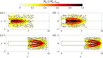
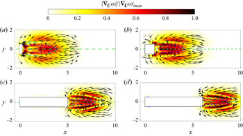
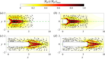
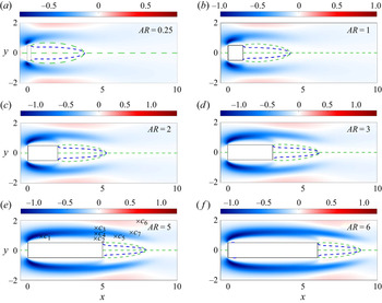
Figures 7 and 8 report the growth rate sensitivity  $\boldsymbol {\nabla }_{\boldsymbol {U}} \lambda$ and the frequency sensitivity
 $\boldsymbol {\nabla }_{\boldsymbol {U}} \omega$ for rectangular cylinders with
 $AR=0.25,1,5,6$ at their critical Reynolds number
 $\textit {Re}_c$. They represent the complete range of
 $AR$ studied in this work. Both
 $\boldsymbol {\nabla }_{\boldsymbol {U}} \lambda$ and
 $\boldsymbol {\nabla }_{\boldsymbol {U}} \omega$ are two-dimensional real vector fields: their field lines provide the local orientation of the sensitivity field, whereas their magnitude provides its intensity.
Here  $\boldsymbol {\nabla }_{\boldsymbol {U}}\lambda$: absolute value and field lines with
 $AR=0.25$ at
 $\textit {Re}=37.8$ (a);
 $AR=1$ at
 $\textit {Re}=44.6$ (b);
 $AR=5$ at
 $\textit {Re}=98.8$ (c);
 $AR=6$ at
 $\textit {Re}=107.5$ (d). The dashed lines are as in figure 6.

Here  $\boldsymbol {\nabla }_{\boldsymbol {U}}\omega$ with panels as in figure 7.

Let us first focus on  $\boldsymbol {\nabla }_{\boldsymbol {U}} \lambda$ in figure 7. First, we observe that
 $\boldsymbol {\nabla }_{\boldsymbol {U}} \lambda$ always vanishes far from the cylinder, owing to the spatial segregation of the direct and adjoint modes, and for
 $AR >3$, it becomes negligible also on the horizontal sides of the cylinder. Also
 $\boldsymbol {\nabla }_{\boldsymbol {U}} \lambda$ strongly depends on the aspect ratio: at small
 $AR$, it is qualitatively similar to the results found for the circular cylinder by Marquet et al. (Reference Marquet, Sipp and Jacquin2008), but for larger
 $AR$ qualitative changes are observed. For
 $AR=0.25$, the largest values of
 $| \boldsymbol {\nabla }_{\boldsymbol {U}} \lambda |$ are observed close to the TE corners, and within the reverse-flow region, with a maximum placed on the centreline at
 $x=0.976$. For
 $AR=1$, the sensitivity in the reverse-flow region becomes stronger. The peak is shifted downstream at
 $x=3.60$. Interestingly, for this
 $AR$, two additional regions of large sensitivity appear in the separation bubble, starting from the rear corners, just outside the reverse-flow region. At larger
 $AR$ the picture changes again. As shown in figure 7(b,d) for
 $AR=5$ and
 $AR=6$, the sensitivity decreases in the core of the reverse-flow region dropping almost to zero for
 $AR=5$. The largest values are instead observed in four lobes placed symmetrically with respect to the
 $y=0$ axis. For
 $AR=5$, the first pair of lobes is placed just outside the reverse-flow region whereas the other pair is placed inside it. The first pair moves just outside the recirculation bubble for
 $AR=6$, while the second pair moves downstream. Quantitatively, the sensitivity maximum is placed at the end of the separation bubble, i.e. at
 $(x,y) \approx (8.03,0)$ for
 $AR=5$ and
 $(x,y) \approx (9.01,0)$ for
 $AR=6$, confirming that at large
 $AR$ the largest changes of
 $\lambda$ are observed for base-flow modifications occurring in the separation bubble or just downstream of its end.
The effect of  $AR$ is also observed on the field lines of
 $\boldsymbol {\nabla }_{\boldsymbol {U}} \lambda$. Indeed, at the lower aspect ratios,
 $AR=0.25$ and
 $AR=1$, similarly to what is observed for the circular cylinder, the field lines in the reverse-flow region are directed upstream. Therefore, increasing the reverse flow will enhance the instability. This makes sense, since a stronger reverse flow increases the instability feed-back. The instability is also enhanced by a thinner separation bubble. For larger
 $AR$, instead, in the portion of the reverse-flow region that is near to the cylinder, the field lines point downstream. A further difference is close to the TE corners, where for
 $AR \leqslant 1$ the lines are directed towards
 $y=0$ from the outer region of the flow, whereas for larger
 $AR$ they switch direction pointing from the centreline outwards. This provides evidence that the same base flow modification leads to different effects depending on
 $AR$. For example, a
 $\delta \boldsymbol {U}$ which increases the backflow velocity in the recirculating region has a strong destabilising effect (i.e.
 $\delta \lambda >0$) for
 $AR \leqslant 1$, but a much lower effect for larger
 $AR$. In contrast, a base-flow modification
 $\delta U >0$ in the separated region has a strong destabilising effect for
 $AR >1$, but an almost negligible effect for smaller
 $AR$.
Let us now observe  $\boldsymbol {\nabla }_{\boldsymbol {U}} \omega$ in figure 8. Like
 $\boldsymbol {\nabla }_{\boldsymbol {U}} \lambda$, it vanishes far from the cylinder, and depends on
 $AR$. For
 $AR=0.25$, the largest values are observed in four different regions: just downstream of the TE, on the
 $U=0$ line, in two lobes at the edge of the reverse-flow region and in two other lobes outside the recirculation bubble. For
 $AR \geqslant 1$, the sensitivity progressively decreases just behind the TE, while it increases in the other regions. The two lobes just outside the reverse-flow region move farther with respect to the symmetry axis, while those located outside the recirculation bubble gradually move downstream. The field lines of
 $\boldsymbol {\nabla }_{\boldsymbol {U}} \omega$ also depend on
 $AR$. Indeed, for
 $AR=0.25$ they are directed upstream in the region behind the TE, where
 $| \boldsymbol {\nabla }_{\boldsymbol {U}} \omega |$ is maximum, whereas for larger
 $AR$ the lines are directed downstream in the reverse-flow region. This means that a
 $\delta \boldsymbol {U}$ which increases the backflow in this region leads to different effects depending on the aspect ratio:
 $\delta \omega >0$ for
 $AR=0.25$ and
 $\delta \omega <0$ for
 $AR \geqslant 1$.
3.5. Sensitivity to a steady force
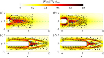
Figures 9 and 10 plot the growth rate sensitivity  $\boldsymbol {\nabla }_{\boldsymbol {F}} \lambda$ and the frequency sensitivity
 $\boldsymbol {\nabla }_{\boldsymbol {F}} \omega$ to a steady force for rectangular cylinders with
 $AR=0.25,1,5,6$ at their critical Reynolds number
 $\textit {Re}_c$. They are representative of the complete range of
 $AR$ studied in this work.
Here  $\boldsymbol {\nabla }_{\boldsymbol {F}}\lambda$ with panels as in figure 7.

Here  $\boldsymbol {\nabla }_{\boldsymbol {F}}\omega$ with panels as in figure 7.

Let us first focus on the growth-rate sensitivity depicted in figure 9. For low aspect ratios ( $AR=0.25,1$),
 $| \boldsymbol {\nabla }_{\boldsymbol {F}} \lambda |$ is largest near the rear corners and in the reverse-flow region. For
 $AR=0.25$, two further lobes are barely visible outside the recirculation bubble; by increasing
 $AR$ they first disappear, then reappear with slightly larger intensity. Near the rear corners the sensitivity is still strong, while it decreases substantially on the symmetry axis in the reverse-flow region becoming stronger on its boundary near the
 $U=0$ line. Interestingly, unlike
 $| \boldsymbol {\nabla }_{\boldsymbol {U}} \lambda |$,
 $| \boldsymbol {\nabla }_{\boldsymbol {F}} \lambda |$ is non-negligible on the top and bottom sides of the cylinder up to the LE, especially at the lower
 $AR$. This suggests that a localised steady force applied on the top/bottom of the cylinders may be effective in altering the flow stability.
The field lines of  $\boldsymbol {\nabla }_{\boldsymbol {F}} \lambda$ are directed upstream in the recirculation region, and have an elliptical shape outside the separated region. For large
 $AR$, a second region with lines directed upstream appear above the separated region. Moreover, along the top and bottom edges of the cylinder with
 $AR \geqslant 5$ the lines are directed upstream rotating anticlockwise close to the LE corners, implying that here a localised steady force may have a stabilising or destabilising effect depending on the distance from the cylinder wall.
The sensitivity  $\boldsymbol {\nabla }_{\boldsymbol {F}} \omega$, plotted in figure 10, shows a stronger dependence on
 $AR$. It is consistently large close to the TE corners and within the reverse-flow region, with the field lines directed downstream for all
 $AR$. For
 $AR \geqslant 5$, the field lines locally switch direction and direct upstream in the region just outside the separation bubble where, however, the sensitivity is low. It is quite large along the sides of the rectangle, at a distance which slightly grows with
 $AR$, and for
 $AR \geqslant 1$ outside the recirculation bubble, with the maximum value reached at a distance from the bubble increasing with
 $AR$.
Overall, a downstream-directed steady force applied within the reverse-flow region, or in the region close to the TE corners, is predicted to have a stabilising effect, producing  $\delta \lambda <0$ and
 $\delta \omega >0$. On the other hand, a downstream force applied above or below the reverse-flow region at
 $y \approx \pm 1$ has a destabilising effect, producing
 $\delta \lambda >0$ but still leading to
 $\delta \omega > 0$. Interestingly, for
 $AR > 3$ an upstream force along the streamwise edges of the cylinder has a stabilising effect with
 $\delta \lambda <0$ when placed near the cylinder surface, i.e.
 $y_0 \approx 0.5$, but a destabilising effect at larger
 $y$; this is verified below.
3.6. Passive control of the primary instability
It is known (Strykowski & Sreenivasan Reference Strykowski and Sreenivasan1990) that a small control cylinder placed in the wake of a bluff body can alter or even suppress vortex shedding. For the circular cylinder, and for a Reynolds number close to  $\textit {Re}_c$, they determined where the control cylinder, with a radius one tenth of that of the main cylinder, should be placed in the flow to suppress the shedding. Here, we extend the analysis done by Marquet et al. (Reference Marquet, Sipp and Jacquin2008) for the circular cylinder, and determine the optimal placement of a small control cylinder to suppress shedding from square cylinders with different aspect ratios (
 $AR=0.25,1,2,3,5,6$) at
 $\textit {Re} \approx \textit {Re}_c$. The presence of the control cylinder is modelled by a point source of momentum
 $\boldsymbol {F}$ in the Navier–Stokes equations, applied at the centre
 $(x_0,y_0)$ of the control cylinder. Owing to the low Reynolds number, the wake of the control cylinder is always steady, regardless of its placement. Hence, the control cylinder is modelled as a localised force acting in a direction opposite with respect to that of the base flow, with modulus proportional to the square of the base-flow speed,
 \begin{equation} \delta \boldsymbol{F}(\boldsymbol{x}) ={-}\alpha U \boldsymbol{U} \ \delta (\boldsymbol{x} - \boldsymbol{x_0}), \end{equation}
with  $0<\alpha \ll 1$. The resulting changes in growth rate and frequency are written as
 \begin{equation} \left.\begin{gathered} \delta \lambda ={-}\alpha U \boldsymbol{\nabla}_{\boldsymbol{F}} \lambda \boldsymbol{\cdot} \boldsymbol{U}, \\ \delta \omega ={-}\alpha U \boldsymbol{\nabla}_{\boldsymbol{F}} \omega \boldsymbol{\cdot} \boldsymbol{U}. \end{gathered}\right\} \end{equation}
Since  $\textit {Re} \approx \textit {Re}_c$ and the flow is marginally stable, i.e.
 $\lambda \approx 0$,
 $\delta \lambda <0$ implies a stabilisation of the flow.
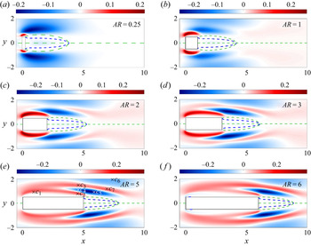
Figure 11 shows how the normalised growth-rate change  $\delta \lambda /\alpha$ varies with the location of the control cylinder. For every
 $AR$, putting a control cylinder in the region just outside the shear layer separating from the LE corners, and down to the TE corners of the rectangle, has a destabilising effect, i.e.
 $\delta \lambda >0$, whereas a cylinder inserted just outside the separation bubble has a stabilising effect. For
 $AR \geqslant 3$ a second destabilising region emerges, located outside the stabilising one near the separation bubble, and connects with the other destabilising region for
 $AR \geqslant 5$. This new destabilising region ensues because of the field lines of
 $\boldsymbol {\nabla }_{\boldsymbol {F}} \lambda$, which for such aspect ratios are directed upstream in this region. For the largest aspect ratio, a thin stabilising region emerges in the shear layer separating from the LE corners.


The normalised frequency change  $\delta \omega /\alpha$ due to a control cylinder is shown in figure 12 for the same
 $AR$ and
 $\textit {Re}$ considered in figure 11. The main effect of the control cylinder, for every
 $AR$, is to decrease the frequency of the instability. The most sensitive region is near the LE corners. The sensitivity decreases moving downstream. A slight increase in the frequency can be obtained by inserting the control cylinder far from the symmetry axis, in the outer region for
 $y \approx 1.9$ and
 $x$ corresponding to the separation bubble, or just outside it, but only for
 $AR \geqslant 5$. Again, differences between these regions are explained by the different direction of the field lines of
 $\boldsymbol {\nabla }_{\boldsymbol {F}} \omega$.
These results are useful for a deeper understanding of the instability mechanism. We first observe that the control cylinder always introduces a viscous drag force, opposed to the base flow. Therefore, it is most effective in the high-speed regions, and this is why the largest effects of the control cylinder are observed above and below the cylinder, in the high-speed region, while it is marginal in the separation bubble. The control cylinder acts by reducing the speed locally while increasing it in the surrounding region by the blockage effect. Concerning the growth rate of the instability, we notice that the control cylinder stabilises the flow when placed just outside the recirculation bubble. Reducing the flow speed here reduces the amplification mechanism of the shear layer, thus leading to a more stable flow. The blockage effect is probably the reason why the control cylinder enhances the instability when placed in the regions above and below the rectangle. We observe that the positive and negative sensitivity regions are adjacent to each other, thus suggesting that the underlying mechanism in both regions is the decrease/increase of the shear-layer intensity. The cylinder can act either directly, by reducing the flow speed, or indirectly, by enhancing the flow speed through blockage. For what concerns the frequency of the instability, the control cylinder seems to act reducing the speed in the high-speed region of the base flow. A simple dimensional analysis indicates that this leads to a corresponding reduction in the instability frequency.
3.6.1. Passive control via a control cylinder
The validity of such results is additionally checked by a linear stability analysis, for  $AR=5$ and
 $\textit {Re}=\textit {Re}_c=98.8$, in which an actual control cylinder of circular cross-section and very small diameter
 $d = D/100$ is placed in the flow. A set of seven significant positions for the control cylinder is chosen, as shown in figures 11(e) and 12(e).
As summarised in table 2, the results of the force-based analysis above have been confirmed for six of the seven points considered, i.e.  $c_1-c_6$. Indeed, both the growth rate and the frequency change in the same direction predicted by the linear stability analysis. Note, moreover, that this analysis confirms the prediction of the positions that yield the largest changes of both the growth rate and the frequency. Indeed the largest
 $\delta \lambda$ and
 $\delta \omega$ are found for the control cylinder
 $c_1$ that is placed in the shear layer close to the upstream corner, where the force-based sensitivity predicts the largest values of both
 $\delta \lambda /\alpha$ and
 $\delta \omega /\alpha$. Point
 $c_7$, with coordinates
 $(x,y)=(7.05,1.18)$, is the sole position where a stabilising effect (albeit very small) is computed, but a destabilising effect was predicted by the force-based sensitivity. However, this may be due to nonlinear effects owing to the finite diameter of the control cylinder.
Variations of the growth rate  $\delta \lambda$ and of the frequency
 $\delta \omega$ for
 $AR=5$ and
 $Re_c=98.8$ when a circular control cylinder with diameter
 $d=D/100$ is placed in the flow. Seven significant positions
 $(x_c,y_c)$ are chosen as shown in figures 11(e) and 12(e).

Base flow for  $AR=5$ and
 $Re_c=98.8$ with and without a circular control cylinder with diameter
 $d=D/100$ placed in the flow. The blue-to-red symmetric map is for
 $U$ and the dashed line denotes
 $U=0$. Here: (a) no control cylinder; (b) case
 $c_2$ in table 2, with the control cylinder placed at
 $(x_c,y_c)=(4.579,0.79)$; (c) case
 $c_5$ in table 2 with the control cylinder placed at
 $(x_c,y_c)=(6,0.9)$.

To verify the working mechanism of the control cylinder explained before, we compare the unperturbed base flow with the perturbed base flows computed for two different positions of the control cylinder, one stabilising  $(c_5)$ and one destabilising
 $(c_2)$. Two small symmetric cylinders with diameter
 $d=D/100$ have been used in both controlled cases to preserve the symmetry of the flow and to facilitate the analysis. Comparing the panels in figure 13, we observe that the stabilising cylinder perturbs the base flow by decreasing the flow speed in the high speed region that drives the shear layer, thus reducing the shear layer intensity and the instability, as explained before. The destabilising cylinder, in contrast, reduces the flow speed near the cylinder and, by its blockage, enhances the flow speed in the high-speed region, leading to an increase of the shear-layer intensity and to a more unstable flow. It is worth noting that consistent with the previous discussions, in the destabilising case
 $(c_2)$ the presence of the control cylinder leads to an increase of both the length of the recirculating bubble
 $l_r$ and the minimum negative velocity
 $|U_{{min}}|$, resulting in a larger
 $\widehat {\textit {Re}}_c$, while the opposite occurs in the stabilising case
 $(c_5)$.
4. Rectangular cylinders with rounded corners
For the sole aspect ratio  $AR=1$, Park & Yang (Reference Park and Yang2016) have studied the primary instability when the LE and TE of a square cylinder are rounded, with a radius of curvature
 $R$. They found that
 $\textit {Re}_c$ has a non-monotonic dependence on the parameter
 $D/R$. The most stable configuration was found at
 $D/R=4$. The goal of this section is to expand their study to elucidate the effect of the radius of curvature on the primary instability at different
 $AR$. The following values of
 $D/R$ have been considered:
 $D/R=2,4,8,16,32,64,128$. It is worth noting that
 $D/R=2$ denotes a cylinder with a semicircle at the LE and/or TE and
 $D/R = \infty$ is the limit of sharp corners. This justifies the asymptotic behaviour of figures 14 and 15.
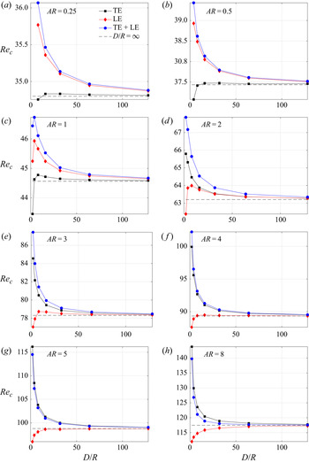
Dependence of  $\textit {Re}_c$ on
 $D/R$ at various
 $AR$. The dashed horizontal line corresponding to sharp corners. The black and red lines indicate rounded corners at the TE and LE, respectively, while for the blue line all corners are rounded.

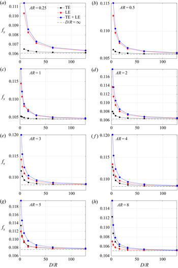
Dependence of  $f_s$ of the unstable eigenvalue at
 $\textit {Re}_c$ on
 $D/R$. Lines and symbols as in figure 14.

In figures 14 and 15, the dependence of  $\textit {Re}_c$ and
 $f_s$ on
 $D/R$ is shown for
 $AR=0.25,0.5,1,2,3,4,5,8$. Rounding the LE corners only (red lines in the figure) produces effects which change across the observed aspect ratios. For
 $AR < 1$, rounding has a stabilising effect that decreases with
 $D/R$. We notice, however, that the largest curvature radii are not considered in the cases with
 $AR=0.25, 0.5$. For
 $1 < AR \leqslant 3$, a non-monotonic dependence of
 $\textit {Re}_c$ on
 $D/R$ is observed. At
 $AR=1$, rounding has a stabilising effect for all the
 $D/R$ with the maximum
 $\textit {Re}_c$ occurring at
 $D/R=4$. For intermediate aspect ratios, i.e.
 $AR=2, 3$, the effect can be stabilising or destabilising depending on
 $D/R$, with destabilisation occurring for very small
 $D/R$, whereas marginal stabilisation occurs for
 $D/R \geqslant 4$. By increasing the aspect ratio, the peak becomes less prominent and slightly shifted towards larger
 $D/R$. Finally, for
 $AR \geqslant 5$, LE rounding has a destabilising effect for all the
 $D/R$, with the most destabilising configuration corresponding to
 $D/R=2$.
When the TE corners are rounded (black lines in the figure), a different scenario arises. For  $AR \geqslant 2$, rounding the LE corners has a stabilising effect for all the
 $D/R$, with the most stable configuration corresponding to the largest rounding radius. For
 $AR \leqslant 1$, instead, rounding has a destabilising effect for sufficiently large curvature radii and stabilising otherwise. The maximum stabilising effect is observed at
 $D/R=8$ for
 $AR=1$ and higher for
 $AR=0.5$ and
 $0.25$. The crossover point, where
 $\textit {Re}_c$ does not change, is shifted towards smaller
 $D/R$ as
 $AR$ increases, up to a point where rounding the TE is always stabilising. Rounding the TE has a larger effect on
 $\textit {Re}_c$ than rounding the LE for
 $AR \geqslant 2$. This is consistent with the structural sensitivities, that show that the leading eigenvalue is more sensitive to flow modifications occurring in the wake region and less sensitive to modifications occurring close to the LE when
 $AR$ is large enough. In contrast, for small
 $AR$, the effect of rounding the LE is found to dominate. Figure 16 qualitatively summarises the stabilising/destabilising effects of the LE and TE rounding, shown by green/red circles.
Qualitative description of the stabilising/destabilising effect of the LE (a) and TE (b) rounding for  $0.25 \leqslant AR \leqslant 8$ and
 $2 \leqslant D/R \leqslant 128$. Green circles indicate stabilising configurations, while red circles the destabilising ones.

Finally, when both LE and TE corners are rounded ( $\textrm {LE}+\textrm {TE}$, blue lines in the figure), a stabilising effect is consistently observed for all
 $AR$ and
 $D/R$. However, some differences among the considered aspect ratios can be observed. Indeed, as found by Park & Yang (Reference Park and Yang2016), for
 $AR=1$,
 $\textit {Re}_c$ has a non-monotonic dependence on
 $D/R$, with the most stabilising configuration corresponding to
 $D/R=4$. For
 $AR<1$ and
 $AR > 1$, instead, a monotonic (decreasing) dependence is recovered. Interestingly, due to nonlinearity, the effect of LE and TE rounding is not additive: for instance, at
 $AR=3$ LE rounding is destabilising, TE rounding is stabilising, but rounding both is more stabilising than rounding the TE alone.
The effect of the rounded corner on the frequency  $f_s$ of the leading eigenvalue is shown in figure 15, and is qualitatively the same at every
 $AR$. Indeed,
 $f_s$ is consistently increased by rounding the corners. For every
 $AR$, the largest drift is observed in the LE+TE configuration. When either LE or TE are considered, LE produces dominant changes for small
 $AR$, but when
 $AR>4$ the opposite occurs, and TE rounding leads to the largest effects.
The changes of  $\lambda$ (or equivalently of
 $\textit {Re}_c$) and
 $f_s$ observed for the rounded-corner configurations can be associated with the sensitivities to base-flow modifications
 $\boldsymbol {\nabla }_{\boldsymbol {U}} \lambda$ and
 $\boldsymbol {\nabla }_{\boldsymbol {U}} \omega$ shown in § 3.4. In this analysis,
 $AR=1,2,3,5$ and
 $8$ have been examined, with
 $D/R=2,16$ and
 $32$. The sensitivity results match the physical observations for all cases, with the exception of the low aspect ratios
 $AR \leqslant 3$ with the smallest
 $D/R=2$. In this region of the parameter space, indeed, the modification of the base flow cannot be considered a small perturbation. Therefore, the linearised theory is no longer accurate enough, and second-order sensitivities should be considered. In the following, the cases with
 $AR=3$ at
 $\textit {Re}=78.4$ and
 $AR=8$ at
 $\textit {Re}=107.5$ are considered as an example, investigating the changes produced in the eigenvalues by rounding the TE or LE corners with
 $D/R=16$. These values of
 $AR$ and
 $D/R$ have been chosen because of the significant changes in
 $\lambda$ and
 $\omega$. Moreover, this choice enables us to compare two cases that have different behaviours with respect to an intermediate value of the LE radius, with stabilising effect for
 $AR < 5$ and destabilising elsewhere, see figure 14.
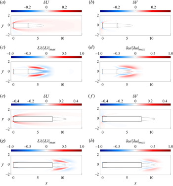
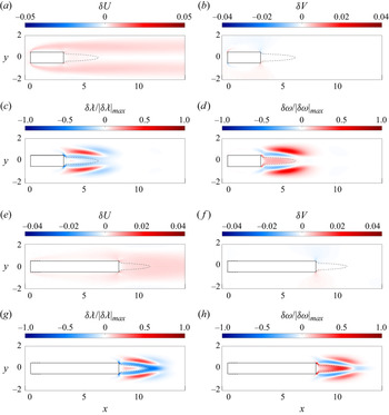
In figure 17, the configuration with rounded LE corners is considered. Panels (a,b,e,f) report the base-flow modifications  $\delta U$ (figure 17a) and
 $\delta V$ (figure 17b) due to rounding the LE corners and the normalised quantities
 $\delta \lambda / | \delta \lambda |_{max}$ (figure 17c) and
 $\delta \omega / | \delta \omega |_{max}$ (figure 17d), computed in the sharp-corner configuration for
 $AR=3$. In the same figure, panels (c,d,g,h) show the same information for
 $AR=8$. Here
 $\delta \lambda$ and
 $\delta \omega$ are defined as
 \begin{equation} \left.\begin{gathered} \delta \lambda(x,y) = \boldsymbol{\nabla}_{\boldsymbol{U}} \lambda(x,y) \boldsymbol{\cdot} \delta \boldsymbol{U}(x,y), \\ \delta \omega(x,y) = \boldsymbol{\nabla}_{\boldsymbol{U}} \omega(x,y) \boldsymbol{\cdot} \delta \boldsymbol{U}(x,y). \end{gathered}\right\} \end{equation}
Rounding the LE corners leads to an increase of the streamwise velocity component,  $\delta U>0$, upstream of the cylinder and in the separated region that originates at the LE;
 $\delta V$ is antisymmetrical with respect to the
 $y$ axis, it is positive just upstream of the LE top corner, and becomes negative in the separated region. Although not visible in the figure, rounding the LE corners affects the base flow downstream of the cylinder too, with a slightly stronger backflow in the reverse-flow region,
 $\delta U<0$. For
 $AR \leqslant 4$, however, an increase of the streamwise velocity is observed at the end of the reverse-flow region,
 $\delta U>0$. This difference is due to the fact that the accelerated shear layers separating from the LE affect the region behind the cylinder farther downstream as
 $AR$ is increased, owing to their interaction with the TE corner. It is worth reporting that the portion of the reverse-flow region with
 $\delta U>0$ increases for the smallest
 $AR$. Overall, these changes of
 $\delta \boldsymbol {U}$ lead to variations of
 $\lambda$ that depend on the considered flow region. For the present cases, a tiny region with
 $\delta \lambda > 0$ is observed just upstream of the LE corners, with a region of opposite sign just downstream. Notably, the largest changes of
 $\delta \lambda$ take place downstream of the cylinder. These regions with
 $\delta \lambda >0$ are located outside the separation bubble. This area is surrounded by zones of negative
 $\delta \lambda$, both inside the separation bubble and far from it. Although changes of the base flow are quite small behind the cylinder, the expected variation
 $\delta \lambda$ is not negligible because
 $\boldsymbol {\nabla }_{\boldsymbol {U}}\lambda$ is large there. Due to the different sign observed at the end of the reverse-flow region and immediately downstream for
 $\delta U$ for the two
 $AR$, as described above,
 $\delta \lambda$ assumes large negative values in this region for
 $AR=3$, while positive or slightly negative values for
 $AR=8$. Consistently with
 $\delta U$, the area with negative
 $\delta \lambda$ at the end of the reverse-flow region increases as
 $AR$ is reduced.
Effect of rounding the LE corners with  $D/R=16$ for
 $AR=3$ at
 $\textit {Re}=78.4$ (a–d) and for
 $AR=8$ at
 $\textit {Re}=117.5$ (e–h), plotted over the sharp-corner geometry. The panels of each group are organised as follows: (a,b,e,f) base flow modifications
 $\delta U$ (a,e) and
 $\delta V$ (b,f); (c,d,g,h)
 $\delta \lambda = \boldsymbol {\nabla }_{\boldsymbol {U}} \lambda \boldsymbol {\cdot } \delta \boldsymbol {U}$ (c,g) and
 $\delta \omega = \boldsymbol {\nabla }_{\boldsymbol {U}} \omega \boldsymbol {\cdot } \delta \boldsymbol {U}$ (d,h). The black dashed line indicates
 $U=0$.

The variations  $\delta \lambda$ assume both signs in the domain. Notably, this is in accordance with the prediction of the stability analysis, which suggests a globally stabilising effect for
 $AR=3$ and a globally destabilising effect for
 $AR=8$. Indeed, by taking the volume integral of the changes
 $\delta \lambda$ over the computational domain
 $\varOmega$,
 \begin{equation} \Delta \lambda = \int_\varOmega \delta \lambda \,\text{d} \varOmega, \end{equation}
 $\Delta \lambda < 0$ is obtained for
 $AR=3$ and
 $\Delta \lambda >0$ for
 $AR=8$. This holds true also for the other
 $AR$ and intermediate
 $D/R$, with
 $\Delta \lambda <0$ for
 $AR \leqslant 4$ and
 $\Delta \lambda >0$ for
 $AR \geqslant 5$. Hence, for the largest
 $AR$, the destabilising effect associated with rounding the LE corners is mainly due to the flow acceleration
 $\delta U$ occurring outside the separation bubble downstream of the TE and to the acceleration of the LE shear layers close to the upstream corners. An explanation is that increasing the velocity outside the separation bubble increases the vorticity in the shear layers, with a consequent destabilising effect. For the smallest
 $AR$, instead, the same rounding has a stabilising effect due to the positive
 $\delta U$ at the end of the reverse-flow region and immediately downstream.
Changes of  $\delta \omega$ are also symmetric with respect to
 $y=0$, and are mainly observed in two different regions of the flow: near the LE corners and outside the separation bubble, in the rear end of the cylinder. Above the top LE corner, there is a small region of positive values surrounded by a larger negative area that marks the LE separation. The most evident changes are again downstream, with relatively large regions with
 $\delta \omega$ of either sign flanking the border of the separation bubble. As for
 $\delta \lambda$, the differences between the two
 $AR$ considered is associated with the different
 $\delta U$ at the end of the reverse-flow region. Here,
 $\delta \omega$ is positive for
 $AR=3$ and negative for
 $AR=8$. Also, the integral of these changes confirms the linear stability analysis, as for both
 $AR$,
 \begin{equation} \Delta \omega = \int_\varOmega \delta \omega \,\text{d} \varOmega > 0. \end{equation}
However, the integral is larger for  $AR=3$ than for
 $AR=8$, owing to the positive contribution of the reverse-flow region; this is consistent with the results of the linear stability analysis, predicting smaller
 $\delta \omega$ as
 $AR$ increases, see figure 15.
Figure 18 is structured as figure 17, but the TE corners are rounded in this case, with a stabilising effect. The base-flow modifications are smaller with respect to the previous case and propagate up to the LE. In particular,  $\delta U>0$ has its maximum close to the TE corners, but its value is not negligible in a large area, especially near the cylinder sides and in the wake. Now
 $\delta V$, in contrast, is quite localised at the LE and TE corners. Small
 $AR$ feature a lower
 $\delta U>0$ in the reverse-flow region and in general over the
 $y=0$ line. As above, this is due to the different interaction between the LE shear layer and the TE corners. Unlike the previous case, however, significant
 $\delta \lambda$ and
 $\delta \omega$ are only observed downstream. A thick region with
 $\delta \lambda <0$ is seen close to the
 $U=0$ line starting from the TE corners, whereas
 $\delta \lambda >0$ is flanking it, in the reverse-flow region and in the external region. For
 $AR=8$ this region of negative
 $\delta \lambda$ has larger intensity, due to the larger
 $\delta U>0$. The integral of these changes leads to
 $\Delta \lambda < 0$ for both
 $AR$ considered, as confirmed by the linear stability analysis. The larger negative
 $\delta \lambda$ over the
 $U=0$ line leads to a more negative
 $\Delta \lambda$ for
 $AR=8$, consistently with what shown in figure 14. Differently, for both
 $AR$, an area with large
 $\delta \omega >0$ is observed in the reverse-flow and external regions, separated by
 $\delta \omega <0$. Overall,
 $\Delta \omega$ is positive, confirming once again the result of the linear stability analysis. This indicates that the stabilising effect associated with rounding the TE corners is due to
 $\delta U>0$ occurring close to the rear corners and to the
 $U=0$ line delimiting the reverse-flow region; the increased value of the frequency is associated with the reduced backflow occurring in the same region, and to the
 $\delta U>0$ in the outer region downstream of the cylinder.
The stabilising/destabilising effect of rounding the corners is consistent with the changes of  $\widehat {\textit {Re}}_c$. Again, we refer to the above considered cases for
 $AR=3$ and
 $AR=8$ with
 $D/R=64$. For
 $AR=3$ the LE rounding results in a stabilising effect and, therefore, to a decrease of
 $\widehat {\textit {Re}}_c$. In this case
 $|U_{{min}}|$ slightly increases as witnessed by the negative
 $\delta U<0$ within the reverse-flow region, and the decrease of
 $\widehat {\textit {Re}}_c$ is due to the decrease of
 $l_r$, visible in figure 17(a) by the positive
 $\delta U>0$ at the end of the reverse-flow region. For
 $AR=8$ the LE rounding has a destabilising effect, with an increase of
 $\widehat {\textit {Re}}_c$. Unlike for smaller
 $AR$, in this case the dominant effect is the slight increase of
 $|U_{{min}}|$. Indeed,
 $l_r$ is almost unchanged owing to the interaction of the accelerated shear layer separating from the LE with the TE corners. Rounding the TE corners has a stabilising effect for both
 $AR$, and
 $\widehat {\textit {Re}}_c$ decreases. In this case this is due to a combination of the decrease of both
 $|U_{{min}}|$ and
 $l_r$, as indicated by the positive
 $\delta U>0$ in the overall reverse-flow region.
5. Conclusions
The flow past rectangular cylinders is of paramount interest from both academic and applied viewpoints, especially in the field of vortex-induced vibrations. The present work has thoroughly investigated, for the first time, the properties of the primary instability of the flow past rectangular cylinders as a function of the aspect ratio  $AR$ and of the rounding of the body corners, highlighting strong qualitative and quantitative changes.
Several properties of the primary instability have been shown to depend on the aspect ratio. The primary instability is invariably the result of a Hopf bifurcation, as for the circular cylinder. However, the critical Reynolds number  $\textit {Re}_c$ is an increasing function of the aspect ratio, starting from
 $\textit {Re}_c \approx 34.8$ at very small
 $AR$, increasing to
 $\textit {Re}_c \approx 44.5$ for the square cylinder at
 $AR=1$ and to a value of
 $\textit {Re}_c \approx 140$ for
 $AR=30$. The instability has been fully characterised and explained through the whole range of aspect ratios. Interestingly, the wave-maker region is always localised in two separated lobes symmetrically placed across the separation bubble in the wake, showing that the smaller recirculations appearing near the upstream corners for
 $AR \geqslant 6$ are not involved in triggering the primary instability. The core of the primary instability moves downstream by increasing
 $AR$ and it only involves the area just outside the separation bubble at the largest
 $AR$.
The aspect ratio also affects the sensitivity to base-flow modifications and to external forcing. The sensitivity to steady forces has been used to compute the proper positioning of a small control cylinder intended to modify the onset of the primary instability; again a quantitative and qualitative dependence on  $AR$ is observed. For all the aspect ratios, a control cylinder placed in the region above the shear layer that separates from the LE corners, or downstream the TE corners, has been found to destabilise the flow; when placed above the reverse-flow region, the control cylinder has a stabilising effect. However, for
 $AR>3$ an additional destabilising region has been identified outside the wake. An explanation for the stabilising/destabilising effects has been provided.
Rounding the corners affects the primary instability in a non-trivial way that depends on the aspect ratio and on the curvature radius  $R$. We have extended the work of Park & Yang (Reference Park and Yang2016), who only studied a square cylinder and rounded all the corners simultaneously (i.e. changing from a square to a circle), by considering the whole range of
 $AR$ and rounding the fore/aft corners independently. Rounding all the corners simultaneously always stabilises the flow. However, the same does not hold true when only the LE or TE corners are rounded. Indeed, rounding the LE corners consistently stabilises the flow for
 $AR \leqslant 1$ and destabilises it for
 $AR \geqslant 5$. For intermediate
 $AR$s, instead, its effect strongly depends on the curvature radius: it is destabilising for large
 $R$ and stabilising for small
 $R$. In contrast, rounding the TE corners has a stabilising effect for all
 $AR$ and
 $R$, with the exception of
 $AR \leqslant 1$ when the largest curvature radii are considered. We provided an explanation of these phenomena, observing that such stabilising and destabilising effects are related to the base-flow modifications with respect to the sharp-corner configuration.
Finally, we highlighted the important role of the minimum speed in the reverse flow region and of the length of the recirculation bubble to predict the stability of the flow as a function of  $AR$ and of the radius of curvature of the corner fillets.
Effect of rounding the TE corners with  $D/R=16$ for
 $AR=3$ at
 $\textit {Re}=78.4$ (a–d) and for
 $AR=8$ at
 $\textit {Re}=117.5$ (e–h), plotted over the sharp-corner geometry. The panels of each group are organised as follows: (a,b,e,f) base-flow modifications
 $\delta U$ (a,e) and
 $\delta V$ (b,f); (c,d,g,h)
 $\delta \lambda = \boldsymbol {\nabla }_{\boldsymbol {U}} \lambda \boldsymbol {\cdot } \delta \boldsymbol {U}$ (c,g) and
 $\delta \omega = \boldsymbol {\nabla }_{\boldsymbol {U}} \omega \boldsymbol {\cdot } \delta \boldsymbol {U}$ (d,h). The black dashed line indicates
 $U=0$.

Declaration of interests
The authors report no conflict of interest.
Appendix A. Sensitivity of the results to domain size and resolution
In this section, the sensitivity of the leading eigenvalue to domain size and grid resolution is briefly investigated. This is done by performing the stability computations for the rectangular cylinder with  $AR=5$ on seven additional meshes (
 $M_1-M_7$). This value of the aspect ratio has been chosen as it is the most delicate, since for larger
 $AR$ the domain size is increased. Results of the sensitivity study are summarised in table 3.
Variations of the critical Reynolds number  $Re_c$ and frequency
 $\textrm {Im}(\sigma _c)$ for the unstable global mode of the rectangular cylinder with
 $AR=5$ on seven different meshes
 $M_1-M_7$, where
 $M_0$ indicates the mesh used for the stability computations in this work,
 $M_1-M_5$ indicate the meshes with different cross-stream extension
 $L_y$,
 $M_6$ is the mesh with larger streamwise extension
 $L_x$ of the domain and
 $M_7$ is the mesh with finer grid resolution.

Five meshes ( $M_1-M_5$) have been used to investigate the sensitivity to the cross-stream extent of the domain, varying
 $L_y$ in the range
 $20D \leqslant L_y \leqslant 80D$. The number of triangles is changed to maintain the resolution almost constant. The cross-stream extent of the domain mainly affects
 $\textrm {Im}(\sigma _c)$ as it is sensitive to the confinement effect. By increasing
 $L_y$ from
 $20D$ to
 $80D$ the change of
 $\textrm {Im}(\sigma _c)$ is approximately
 $4\,\%$. For the chosen value of
 $L_y=40D$,
 $Re_c$ and
 $\textrm {Im}(\sigma _c)$ are within
 $0.26\,\%$ and
 $0.89\,\%$ the values predicted for
 $L_y=60D$ and within
 $0.34\,\%$ and
 $1.04\,\%$ of those predicted for the largest cross-stream extension considered,
 $L_y=80D$. Mesh
 $M_6$ has been used to investigate the sensitivity to the streamwise extent of the domain. The position of the outlet is shifted downstream with the domain extending
 $-25 \leqslant x \leqslant 70$, and – in this case too – the number of triangles is increased to guarantee the same spatial resolution. With the longer domain
 $Re_c$ is within
 $0.12\,\%$ of the value predicted by the the used mesh
 $M_0$, while
 $\textrm {Im}(\sigma _c)$ is unchanged up to the third significant digit. Lastly, mesh
 $M_7$ has been used to investigate the sensitivity to the grid resolution. The same domain as
 $M_0$ is used, but the number of triangles is increased of approximately
 $50\,\%$, mainly increasing the resolution near the cylinder and in the wake region. Again both
 $Re_c$ and
 $\textrm {Im}(\sigma _c)$ are almost insensitive to this increase of the resolution as their change is, respectively, of
 $0.02\,\%$ and less than
 $0.01\,\%$.