1. Introduction
Three-dimensional (3-D) surface waviness has emerged as an effective passive flow control strategy for suppressing vortex shedding and mitigating unsteady drag and lift forces on bluff bodies (Zdravkovich Reference Zdravkovich1981; Naudascher & Rockwell Reference Naudascher and Rockwell2006; Ekmekci & Rockwell Reference Ekmekci and Rockwell2010). The concept of waviness is frequently observed in nature and has been shown to enhance hydrodynamic and aerodynamic performance. For example, humpback whale flippers exhibit leading-edge tubercles that reduce flow separation and improve lift (Fish & Lauder Reference Fish and Lauder2006; Cai et al. Reference Cai, Zuo, Maeda, Kamada, Li, Shimamoto and Liu2017; Gopinathan & Bruce Ralphin Rose Reference Gopinathan and Bruce Ralphin Rose2021; Ferreira et al. Reference Ferreira, Moura and de Araújo2025; Luo et al. Reference Luo, Lu, Bai and Yang2025; Pinapatruni et al. Reference Pinapatruni, Sinha, Lua and Dash2025), daffodil stems show geometric undulations that increase structural stability in wind (Etnier & Vogel Reference Etnier and Vogel2000; Kim et al. Reference Kim, Lee and Choi2012, Reference Kim, Lee and Choi2016; Yoon, Kim & Wei Reference Yoon, Kim and Wei2018; Zhdanov, Green & Busse Reference Zhdanov, Green and Busse2023) and harbour seal vibrissae possess unique surface undulations that suppress vortex-induced vibrations for sensitive flow detection (Hanke et al. Reference Hanke, Witte, Miersch, Brede, Oeffner, Michael, Hanke, Leder and Dehnhardt2010; Kim & Yoon Reference Kim and Yoon2017, Reference Kim and Yoon2018a , Reference Kim and Yoonb ; Chu et al. Reference Chu, Xia, Wang, Fan and Yang2021; Chen, Min & Guo Reference Chen, Min and Guo2022; Chen et al. Reference Chen, Liu, Zang and Azarpeyvand2025; Shan & Zhang Reference Shan and Zhang2025; Yao et al. Reference Yao, Hu, Tang, Fu, Shan and Li2025). Inspired by these biological examples, numerous studies, (Kim, Lee & Choi Reference Kim, Lee and Choi2012; Jung & Yoon Reference Jung and Yoon2014; Yoon et al. Reference Yoon, Nam and Kim2020a ; Nam & Yoon Reference Nam and Yoon2022; Zhu et al. Reference Zhu, Yuan, Hu, Yang and Xu2024; Kim, Yoon & Nair Reference Kim, Yoon and Nair2025) have explored bio-inspired wavy geometries and demonstrated their effectiveness in modulating wake structures and reducing fluid-induced forces. More recent work, (Yoon, Shin & Kim Reference Yoon, Shin and Kim2017; Moon & Yoon Reference Moon and Yoon2020; Yoon et al. Reference Yoon, Nam and Kim2020b ) has introduced superimposed or hybrid undulation patterns to further enhance flow control performance
Despite this progress, the coupled effects of undulation orientation (i.e. the direction of geometric modulation) and spanwise cross-sectional variation remain insufficiently understood, particularly in relation to their impact on vortex evolution, wake stabilisation and force characteristics. A systematic investigation into these geometric parameters is essential to advance our understanding of 3-D wake transition mechanisms and to guide the development of more effective passive flow control strategies for engineering applications.
Undulated surfaces introduce significant modifications to flow characteristics, influencing vortex dynamics and aerodynamic performance. A key mechanism widely observed in wavy configurations is the delay of vortex roll-up, which suppresses vortex shedding in the near wake. This suppression has been demonstrated in both wavy circular and elliptical cylinders, as well as in bio-inspired geometries such as harbour seal vibrissae (Lam et al. Reference Lam, Wang, Li and So2004; Zhang, Daichin & Lee Reference Zhang and Lee2005; Lam & Lin Reference Lam and Lin2008; Xu, Chen & Lu Reference Xu, Chen and Lu2010; Jung & Yoon Reference Jung and Yoon2014; Kim, Lee & Choi Reference Kim, Lee and Choi2016; Lin et al. Reference Lin, Bai, Alam, Zhang and Lam2016; Wei, Yoon & Jung Reference Wei, Yoon and Jung2016; Kim & Yoon Reference Kim and Yoon2017, Reference Kim and Yoon2018a , Reference Kim and Yoonb ). The weakening of periodic pressure oscillations due to vortex suppression leads to significant reductions in drag and lift fluctuations (Kim et al. Reference Kim, Lee and Choi2012; Jung & Yoon Reference Jung and Yoon2014; Wei et al. Reference Wei, Yoon and Jung2016).
In addition, the formation of zero-vorticity zones – particularly along the shear layer and in the near wake – has been frequently reported. These regions are closely associated with shear layer elongation, which delays flow separation and contributes to wake stabilisation (Lam & Lin Reference Lam and Lin2008; Jung & Yoon Reference Jung and Yoon2014; Wei et al. Reference Wei, Yoon and Jung2016; Yoon et al. Reference Yoon, Shin and Kim2017, Reference Yoon, Oh, Kim, Kim and Moon2020c ). The combined effect of shear layer elongation and reduced vorticity fluctuations enhances downstream flow coherence and promotes global wake stability.
A well-documented consequence of surface undulation is the extension of vortex formation length, which delays vortex shedding and improves aerodynamic efficiency through gradual energy dissipation (Lam & Lin Reference Lam and Lin2008; Jung & Yoon Reference Jung and Yoon2014; Kim et al. Reference Kim, Lee and Choi2016; Lin et al. Reference Lin, Bai, Alam, Zhang and Lam2016; Wei et al. Reference Wei, Yoon and Jung2016). In addition, spanwise undulations induce wavy flow patterns, generating alternating regions of acceleration and deceleration due to local curvature variations (Lam et al. Reference Lam, Wang, Li and So2004; Lam & Lin Reference Lam and Lin2008; Jung & Yoon Reference Jung and Yoon2014; Wei et al. Reference Wei, Yoon and Jung2016). These patterns lead to jet-like structures that enhance wake mixing and suppress turbulent kinetic energy (Jung & Yoon Reference Jung and Yoon2014).
Moreover, undulated geometries give rise to additional transverse and streamwise vortices formed by 3-D separation effects. These vortices help stabilise the wake and maintain flow coherence (Lin et al. Reference Lin, Bai, Alam, Zhang and Lam2016; Yoon et al. Reference Yoon, Shin and Kim2017, Reference Yoon, Oh, Kim, Kim and Moon2020c ). The spanwise pressure gradients introduced by undulations further disrupt large-scale vortex shedding, thereby reducing flow instabilities (Kim et al. Reference Kim, Lee and Choi2016; Wei et al. Reference Wei, Yoon and Jung2016).
The classification of flow patterns in wavy cylinders with circular and elliptical cross-sections has been primarily based on the undulation axis and spanwise wavelength. Early studies, such as those by Lam & Lin (Reference Lam and Lin2007, Reference Lam and Lin2009), focused on vorticity components and the temporal behaviour of force coefficients to define distinct regimes. More recently, Shi et al. (Reference Shi, Bai, Alam, Ji and Zhu2023) introduced a classification approach based on 3-D streamline topologies, offering a more detailed identification of wake structures.
Characteristic flow behaviours have been found to depend strongly on undulation geometry – particularly wavelength and amplitude. In the short wavelength regime, the wake resembles that of a smooth cylinder, with quasi-2-D features and slight spanwise distortions (Lam & Lin Reference Lam and Lin2009). As the wavelength increases, more complex 3-D vortical structures emerge, accompanied by an extended vortex formation length and delayed vortex shedding. In some configurations, vortex roll-up is completely suppressed, leading to a steady wake without vortex formation – an effect reported in certain wavy circular cylinders (Lam & Lin Reference Lam and Lin2007, Reference Lam and Lin2009; Nam & Yoon Reference Nam and Yoon2022). These findings underscore the critical role of undulation geometry – including wavelength, wave amplitude, cross-sectional shape and undulation orientation – in governing wake transitions. They reinforce the need for classification schemes that comprehensively capture spanwise variation and 3-D flow structures (Yoon, Nam & Kim Reference Yoon, Nam and Kim2022; Shi et al. Reference Shi, Bai, Alam, Ji and Zhu2023).
Nam & Yoon (Reference Nam and Yoon2022) investigated the wake patterns of wavy elliptic cylinders at a low Reynolds number (Re = 100) by varying the spanwise wavelength and cross-sectional aspect ratio. Through 3-D iso-surfaces and 2-D distributions of spanwise vorticity, they identified three representative flow regimes for wavy circular cylinders, consistent with earlier observations by Lam & Lin (Reference Lam and Lin2007) and Lam & Lin (Reference Lam and Lin2009). They also analysed the temporal evolution of force coefficients to capture transitions between steady and unsteady states, revealing the coexistence of both flow modes at different spanwise locations under certain geometric conditions.
Extending this classification, Shi et al. (Reference Shi, Bai, Alam, Ji and Zhu2023) proposed five distinct wake patterns based on the ratio of spanwise wavelength to mean diameter (
 $\lambda /L_m$
). Their analysis focused on the formation mechanisms and spatial extent of spanwise and streamwise vortices across the span. Similar to Nam & Yoon (Reference Nam and Yoon2022), they also used the temporal evolution of force coefficients to distinguish between flow patterns. Overall, the five flow patterns identified by Shi et al. (Reference Shi, Bai, Alam, Ji and Zhu2023) can be broadly categorised into three common features: quasi-2-D wake structures, 3-D wake vortex distortions and the absence of free shear layer roll-up accompanied by the lack of vortex shedding.
While passive flow control using undulated surfaces has been extensively explored, several key limitations remain in the existing literature. Most previous studies have focused individually on either wavy circular or elliptic cylinders, without offering a systematic comparison across different geometric configurations. Furthermore, the majority of investigations have considered only a single undulation direction – typically streamwise or transverse – neglecting the combined effects of multi-axis undulations, such as in-phase or anti-phase configurations. In addition, earlier work has often emphasised localised flow features specific to certain cases, rather than presenting a comprehensive view of flow evolution across varied undulation types. Consequently, the influence of combined undulation parameters on wake stabilisation, vortex dynamics and aerodynamic force modulation remains insufficiently understood.
To address these limitations, this study systematically investigates how undulation-induced geometric variations influence vortex topology, wake evolution and aerodynamic performance in wavy cylinders. Unlike previous works focused on single undulation orientations or isolated geometries, this study provides a comprehensive analysis of the effects of various undulation orientations and cross-sectional shapes. Specifically, it examines streamwise undulation (SU), transverse undulation (TU) and anti-phase undulation (APU) in wavy elliptic cylinders, and in-phase undulation (IPU) in wavy circular cylinders. IPU is considered particularly appropriate for circular sections due to their uniform geometry, while SU, TU and APU are used to explore how non-circular (elliptic) sections interact with different waviness orientations. The influence of IPU in elliptic cylinders remains a subject for future study.
A recent study by Kim et al. (Reference Kim, Yoon and Nair2025) explored the aerodynamic effects of undulated geometries at a subcritical Reynolds number (
 $\textit{Re} = 3000$
), focusing on configurations such as SU, TU, APU and IPU. While that study revealed key mechanisms such as spanwise bluffness and transverse protrusion effects, it examined only two specific geometries, each defined by a single wavelength and amplitude, thereby limiting the generalisability of the conclusions across a wider parameter space.
In contrast, the present study investigates the same undulation configurations in a laminar regime
 $(\textit{Re} = 100)$
, where the wake undergoes a 2-D to 3-D transition characterised by coherent vortex evolution rather than turbulent interactions.
A systematically broader wavelength range (
 $\lambda /L_{m} = 1-8$
) is examined while keeping the amplitude fixed, enabling a comprehensive investigation of 2-D to 3-D wake transitions, vortex stabilisation and force modulation trends.
Building on this, the present work introduces a four-stage framework for wake evolution – bifurcation, dislocation, disconnection and re-symmetrisation – linking flow topology directly with aerodynamic response.
The study also identifies a critical wavelength
 $(\lambda _{C}/L_m)$
beyond which spanwise synchronisation stabilises the wake and markedly reduces drag and lift fluctuations, providing the first quantitative measure of geometry-induced wake control in the laminar regime. Furthermore, the role of transverse recirculating flow is clarified as a key mechanism governing wake coherence, vortex suppression and the transition from quasi-2-D to spiral 3-D states.
By revealing these orientation-dependent stabilisation pathways (SU and APU stabilising earlier, TU and IPU delayed), the present study investigates a fundamentally different flow regime and physical mechanism, focusing on laminar 2-D to 3-D transition processes rather than turbulence-induced wake interactions.
Consequently, this work establishes a unified connection between vortex-structure evolution, recirculation dynamics and aerodynamic performance, offering new insight into how spanwise geometric modulation governs wake stability. These findings advance the physics of passive flow control and provide design guidance for bio-inspired and engineering applications requiring enhanced flow stability and aerodynamic efficiency.
The physical insights obtained under low-Reynolds-number conditions are relevant to the development of bio-inspired or small-scale aerodynamic systems, such as micro aerial vehicles, underwater sensors and passive flow-control devices, where stable wake behaviour and low drag are critical for efficient performance.
2. Numerical details
2.1. Definition of geometry
The typical geometries of the undulated cylinders are presented in figure 1, where the cross-section definition and its parameters are also identified. The spanwise local lengths of the wavy elliptic undulated cylinder in the streamwise and cross-flow directions (
 $L_{z,x}$
and
 $L_{z,y}$
, respectively) are described by the following equations:
 \begin{equation} L_{z, x}=L_{m, x}+2 a \cos (2 \pi z / \lambda ), \end{equation}
 \begin{equation} L_{z, y}=L_{m, y}+2 a \cos (2 \pi z / \lambda ). \end{equation}
In (2.1) and (2.2),
 $a$
and
 $\lambda$
represent the wave amplitude and wavelength of the wavy surface, respectively. The
 $L_{m,x}$
and
 $L_{m,y}$
denote the mean axis lengths in the streamwise flow and cross-flow directions, respectively, which are defined as the mean values of the maximum and minimum local axis lengths of the wavy cylinder in each direction.
Geometries and their characteristic parameters for each undulation configuration: (a) streamwise undulation (SU); (b) transverse undulation (TU); (c) anti-phase undulation (APU) and (d) in-phase undulation (IPU). Key geometric quantities such as maximum/minimum local lengths and mean lengths are indicated.

The mean characteristic body length in the direction of undulation, defined as
 $L_m = (L_{max}+L_{min})/2$
, where
 $L_{max}$
and
 $L_{min}$
represent the maximum and minimum local body lengths along the undulation direction. This definition applies to both elliptic and undulated configurations. For the IPU case, where the cross-section is circular, the characteristic length is given by the mean diameter,
 $L_m = (D_{max}+D_{min})/2$
, where
 $D_{max}$
and
 $D_{min}$
denote the maximum and minimum local diameters, respectively.
The wavy surfaces of the streamwise and transverse undulated cylinders (SU and TU) are formed by sinusoidally varying the streamwise and transverse axes (
 $L_{z,x}$
and
 $L_{z,y}$
in (2.1) and (2.2), respectively) of the elliptic cross-section along the spanwise direction (
 $z$
). In SU, the transverse axis of the elliptic cross-section remains constant at
 $L_m$
, while in TU, the streamwise axis remains constant at
 $L_m$
, where
 $L_m = L_{m,x} = L_{m,y}$
. Thus, in SU, the local axis length varies in the streamwise direction, while in TU, it varies in the transverse direction, as shown in figures 1(a) and 1(b).
The anti-phase undulated (APU) cylinder is constructed by combining the undulations of both SU and TU in an anti-phase manner. It incorporates both axes and exhibits alternating waveforms between the streamwise and transverse directions. The spanwise local lengths of the APU cylinder can be described as follows:
 \begin{equation} L_{z, x}=L_{m, x}+2 a \cos (2 \pi z / \lambda ), \end{equation}
 \begin{equation} L_{z, y}=L_{m, y}-2 a \cos (2 \pi z / \lambda ). \end{equation}
The APU configuration and its geometric definition are present in figure 1(c). Thus, the SU, TU and APU configurations are all based on an elliptic cross-section.
In contrast, the in-phase undulated cylinder (IPU) is characterised by a local diameter
 $D_z$
defined as follows:
 \begin{equation} D_{z}=D_{m}+ 2 a \cos (2 \pi z / \lambda )), \end{equation}
where
 $D_m$
denotes the mean diameter of the IPU, corresponding to the diameter of a smooth cylinder. The positions of
 $D_{max }$
,
 $D_m$
and
 $D_{min }$
correspond to the node, middle and saddle points, respectively, as described in figure 1(d). The IPU has been well known as the wavy cylinder in previous studies (Darekar & Sherwin Reference Darekar and Sherwin2001; Lam et al. Reference Lam, Lin, Zou and Liu2012; Jung & Yoon Reference Jung and Yoon2014; Yoon et al. Reference Yoon, Shin and Kim2017, Reference Yoon, Oh, Kim, Kim and Moon2020c
). The IPU is introduced to describe a wavy circular cylinder with a spanwise undulation pattern. Unlike SU and TU, which have an elliptic cross-section with streamwise or transverse undulations, the IPU maintains a circular cross-section while undergoing in-phase deformation along the spanwise direction. This in-phase variation is conceptually analogous to a synchronised combination of the undulation patterns observed in SU and TU, justifying the use of the term IPU. The present range of
 $1.0 \leq \lambda / L_m \leq 8.0$
covers the short and long wavelengths. The wave amplitude of
 $a / L_m = 0.1$
is fixed.
The mean cross-section of all undulated configurations (SU, TU, APU and IPU) is designed to be circular, corresponding to a mean aspect ratio of unity (
 $\textit{AR} = 1.0$
). Due to the sinusoidal deformation (
 $a/L_m=0.1$
), the spanwise local aspect ratio (
 $\textit{AR}$
) varies depending on the undulation mode. For clarity,
 $\textit{AR}_{\textit{SU}}$
,
 $\textit{AR}_{\textit{TU}}$
,
 $\textit{AR}_{\textit{APU}}$
,
 $\textit{AR}_{\textit{IPU}}$
denote the local aspect ratios of the SU, TU, APU and IPU configurations, respectively. The variations are approximately
 $\textit{AR}_{\textit{SU}}, \textit{AR}_{\textit{TU}}\in [0.833,1.25]$
,
 $\textit{AR}_{\textit{APU}} \in [0.667,1.5]$
and
 $\textit{AR}_{\textit{IPU}} = 1$
identically.
These variations lie well within the canonical elliptic-cylinder regimes reported in previous studies (Raman, Arul Prakash & Vengadesan Reference Raman, Arul Prakash and Vengadesan2013; Thompson et al. Reference Thompson, Radi, Rao, Sheridan and Hourigan2014; Shi et al. Reference Shi, Alam, Zhu, Ji, Bai and Sharifpur2024). In particular, Shi et al. (Reference Shi, Alam, Zhu, Ji, Bai and Sharifpur2024) investigated wavy elliptic cylinders at
 $\textit{Re} = 100$
with local aspect-ratio variations
 $(\textit{AR} \approx 0.45{-}1.0)$
, confirming that such moderate ellipticity induces 3-D wake transitions consistent with the range considered in the present study.
Hence, the local ellipticity variation in the present models represents a physically realistic geometric modulation rather than a fundamentally different body shape. The wake structures of these locally elliptic sections are dynamically comparable, though not identical, to those of a circular cylinder at
 $\textit{Re} = 100$
. This supports the physical consistency of the comparison while acknowledging the subtle differences introduced by local ellipticity.
While local ellipticity is geometrically inherent to the undulated configurations, a detailed investigation of its standalone effect would require a systematic parametric study of elliptic cylinders, which lies beyond the present scope. Therefore, the current discussion is limited to demonstrating that the observed local AR variations remain within physically realistic bounds and do not alter the fundamental focus on undulation-induced wake modulation.
2.2. Governing equations and numerical methods
The governing equations of the unsteady 3-D laminar flow of incompressible fluid are the continuity and the Navier–Stokes equations. Therefore, the governing equations are defined as follows:
 \begin{equation} \frac {\partial u_i}{\partial x_i}=0, \end{equation}
 \begin{equation} \frac {\partial u_i}{\partial t}+\frac {\partial u_i u_{\!j}}{\partial x_{\!j}}=-\frac {\partial p}{\partial x_i}+\frac {1}{R e} \frac {\partial ^2 u_i}{\partial x_{\!j} \partial x_{\!j}}, \end{equation}
where
 $u_i$
are the velocity components along the Cartesian coordinates
 $x_i$
,
 $t$
is the time and
 $p$
is the pressure. All variables are non-dimensionalised using the free stream velocity (
 $U_\infty$
) and the mean characteristic body length in the direction of undulation,
 $L_m$
. This non-dimensionalisation produces a dimensionless parameter
 $\textit{Re} = U_\infty L_m / \nu$
, where
 $\nu$
is the kinematic viscosity. In this study, the Reynolds number is set to
 $\textit{Re} = 100$
, which falls within the laminar flow regime for flow over a circular cylinder. All configurations share the same mean circular geometry and Reynolds number (
 $\textit{Re} = 100$
), ensuring that any differences in the resulting wake dynamics arise solely from the direction and phase of the spanwise undulation.
The present study employs the finite volume method (FVM) with a second-order central difference scheme for spatial discretisation and a second-order implicit scheme for temporal discretisation. The convection and diffusion terms are treated using the second-order Adams–Bashforth scheme and the Crank–Nicolson scheme, respectively. The governing equations are formulated in a generalised curvilinear coordinate system, which has been successfully applied to flow simulations around various geometrical disturbances under laminar and subcritical Reynolds number conditions (Jung & Yoon Reference Jung and Yoon2014; Wei et al. Reference Wei, Yoon and Jung2016; Kim & Yoon Reference Kim and Yoon2017; Yoon et al. Reference Yoon, Shin and Kim2017; Kim & Yoon Reference Kim and Yoon2018c ; Moon & Yoon Reference Moon and Yoon2020; Yoon et al. Reference Yoon, Nam and Kim2020a , Reference Yoon, Oh, Kim, Kim and Moonc ).
In the present computations, the dimensionless time step is set to
 $\Delta t = 0.005$
, ensuring that the maximum Courant–Friedrichs–Lewy (CFL) number remains below 0.5 for most of the computational domain. The convergence criterion is set to
 $10^{-4}$
and additional tests with smaller values confirmed no significant changes in the results. Convergence is evaluated at the end of each iteration, with a minimum of five iterations per time step, although typically, only two iterations are sufficient to meet the convergence criterion.
For unsteady flow analysis, the statistically steady state is determined when the time history of lift and drag coefficients reaches a periodic state. To ensure statistical convergence, at least 300 vortex shedding cycles are considered, which was found to be sufficient based on prior studies.
2.3. Computational domain, grid generation and boundary conditions
Figure 2(a) shows the computational domain and boundary conditions used in this study. The domain extends
 $70L_m$
in the streamwise direction and
 $60L_m$
in the transverse direction. The cylinder is placed
 $30L_m$
upstream and
 $40L_m$
downstream of the inlet and outlet boundaries, respectively. In the spanwise direction, a length of
 $2\lambda$
is applied to accommodate the periodic boundary conditions. The present computational domain size in each direction is sufficiently large compared with previous studies (Zheng & Alam Reference Zheng and Alam2017; Kim & Yoon Reference Kim and Yoon2018c
; Shi et al. Reference Shi, Bai, Alam, Ji and Zhu2023). The resulting blockage ratio is as low as 1.67 %. Within this computational domain, the influence of the lateral, inlet and outlet boundaries on the near wake of the cylinder is insignificant, as previously examined by Zheng & Alam (Reference Zheng and Alam2017)
(a) Computational domain and boundary conditions. (b) Grid distributions around the undulated cylinder.

The inflow boundary enforces a uniform velocity profile, while symmetry and periodic boundary conditions are applied in the transverse and spanwise directions. At the outflow, a convective boundary condition,
 $\partial u_i / \partial t + c\, \partial u_i / \partial x = 0$
, where
 $c$
is the space-averaged streamwise outlet velocity, governs the velocity field, while a Neumann condition is imposed for pressure. No-slip and no-penetration conditions are enforced at the cylinder surface.
The generalised curvilinear coordinate system is employed to generate the computational mesh and analyse the results. The mesh is non-uniformly spaced in the x–y plane while remaining structured along the spanwise direction, as illustrated in figure 2(b). A total of 120 grid points is evenly distributed along the cylinder circumference. To capture sharp velocity gradients in the separated shear layers and near wake, finer grids are concentrated around the cylinder surface and wake region, as shown in figure 2(b). The spanwise direction maintains a uniform grid spacing for shorter wavelengths, while for longer wavelengths, the grid spacing is adjusted accordingly. The grid distribution near the surface is also refined according to wavelength variations. As the wavelength decreases, the wave slope steepens, requiring greater grid refinement near the surface. A refined mesh is generated within a circular region of radius
 $5L_m$
around the wavy cylinders. The first grid point is placed at
 $0.01L_m$
from the cylinder surface, with subsequent grids stretched radially in a non-uniform manner. In contrast, in the spanwise direction, the grid spacing is approximately
 $0.03L_m$
for shorter wavelengths, but increases up-to approximately
 $0.06L_m$
for longer wavelengths. The number of spanwise layers ranges from 30 to 320, and the total grid count increases with wavelength, reaching approximately 7.8 million at the longest wavelength. These grid configurations correspond to the medium-grid system employed in the present simulations, which will be discussed in detail in the following subsection.
2.4. Grid independence tests and data validation
The present study conducts a grid independence test and data validation to ensure numerical accuracy in the analysis of wavy cylinders. While differences in Reynolds number and geometric configurations exist, the fundamental computational methodologies and validation approaches remain consistent with those established in previous studies. The authors’ previous research on wavy elliptic cylinders (Nam & Yoon Reference Nam and Yoon2022; Yoon et al. Reference Yoon, Oh, Kim, Kim and Moon2020c ) and harbour seal vibrissae (HSV) (Kim & Yoon Reference Kim and Yoon2017, Reference Kim and Yoon2018a , Reference Kim and Yoonb ; Yoon et al. Reference Yoon, Nam and Kim2020a , Reference Yoon, Oh, Kim, Kim and Moonc ) has demonstrated the effectiveness of similar grid independence tests and validation methods, providing a foundation for the grid refinement strategy adopted in this work
A grid dependence test and validation are conducted for the IPU configuration to assess numerical accuracy. Since the IPU shares the same spanwise undulation characteristics as SU, TU and APU, its results are expected to be applicable to other configurations. By varying the wavelength (
 $\lambda$
), the influence of both spanwise and circumferential resolutions on numerical accuracy is examined to determine appropriate grid spacing for wavy cylinder geometries.
For the grid dependence test, the time-averaged drag coefficient (
 $\overline {C_{\!D}}$
), root-mean-square (r.m.s.) of lift fluctuation (
 $C_{L,\textit{rms}}$
) and Strouhal number (
 $St$
) were analysed for the IPU to examine the influence of grid resolution. For the validation of the numerical methods, the same parameters were compared with previous studies on the smooth circular cylinder to confirm the accuracy of the present approach. The
 $C_{\!D}$
,
 $C_{\!L}$
and
 $St$
are defined as follows:
 \begin{equation} C_{\!D}=\frac {2 F_{\!D}}{\rho U_{\infty }^2\left (L_{m} \boldsymbol{\cdot }\lambda \right )}, \quad C_{\!L}=\frac {2 F_{\!L}}{\rho U_{\infty }^2\left (L_{m} \boldsymbol{\cdot }\lambda \right )}, \quad St=\frac {f_s L_{m}}{U_{\infty }}, \end{equation}
where
 $F_{\!D}$
and
 $F_{\!L}$
are the total drag and lift forces, respectively,
 $\rho$
is the fluid density,
 $U_\infty$
is the free stream velocity,
 $L_m$
is the mean body length, and
 $f_s$
is the frequency of the vortex shedding.
The grid independence test is conducted for two representative wavelengths of
 $\lambda / L_{m} = 2.5$
and
 $\lambda / L_{m} = 8.0$
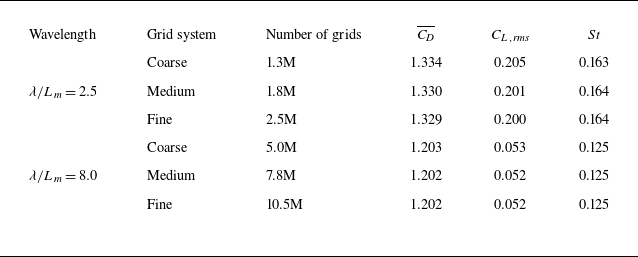
, corresponding to short and long wavelength cases, respectively. These cases are selected to capture the primary trends of grid dependence across different wavelength regimes. Although intermediate wavelengths are not explicitly tested, the selected cases provide insights into the general influence of grid resolution on numerical accuracy. The grid dependence tests adopt three different grid systems, as summarised in table 1. The coarse system contains 1.3 and 5.0M grids, the medium system includes 1.8 and 7.8M grids, and the fine system uses 2.5 and 10.5M grids for
 $\lambda / L_{m} = 2.5$
and
 $\lambda / L_{m} = 8.0$
, respectively.
Grid dependence test for the wavy cylinder (
 $\lambda / L_{m} = 2.5$
and
 $\lambda / L_{m} = 8.0$
) at
 $\textit{Re} = 100$
. The time-averaged drag coefficient (
 $\overline {C_{\!D}}$
), root mean square of the lift coefficient (
 $C_{L,\textit{rms}}$
) and Strouhal number (
 $St$
) are compared across different grid resolutions.

As shown in table 1, the variations in
 $\overline {C_{\!D}}$
,
 $C_{L,\textit{rms}}$
and
 $St$
across different grid resolutions remain within 0.08 % to 2.4 % deviation, indicating that further grid refinement beyond the medium system does not lead to significant improvements in numerical accuracy. Based on these findings, a medium grid resolution strategy (1.8 and 7.8M grids) is adopted to ensure consistent grid resolutions across different
 $\lambda / L_m$
values, while maintaining a balance between computational efficiency and numerical accuracy. This strategy effectively captures the primary flow characteristics, including the influences of spanwise and circumferential resolutions.
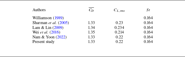
For the validation of the present numerical methods, table 2 presents a comparison of the computed integral parameters (
 $\overline {C_{\!D}}$
,
 $C_{L,\textit{rms}}$
and
 $St$
) with previously reported values. The results show strong agreement with existing numerical and experimental studies, confirming the reliability of the present approach. The present
 $\overline {C_{\!D}}$
closely matches the values reported by Sharman et al. (Reference Sharman, Lien, Davidson and Norberg2005) and Nam & Yoon (Reference Nam and Yoon2022), with a maximum deviation of 1.49 % compared with Wei et al. (Reference Wei, Yoon and Jung2016). Similarly, the present
 $C_{L,\textit{rms}}$
shows a minor difference of 0.85 % from Lam & Lin (Reference Lam and Lin2009). The present
 $St$
remains well aligned with previous studies, exhibiting negligible variation from prior findings. These results confirm that the present numerical methodology provides reliable and validated predictions.
Validation of the present numerical method for the smooth circular cylinder at
 $\textit{Re} = 100$
, compared with previous studies. Time-averaged drag coefficient (
 $\overline {C_{\!D}}$
), root mean square of the lift coefficient (
 $C_{L,\textit{rms}}$
) and Strouhal number (
 $St$
) are presented.

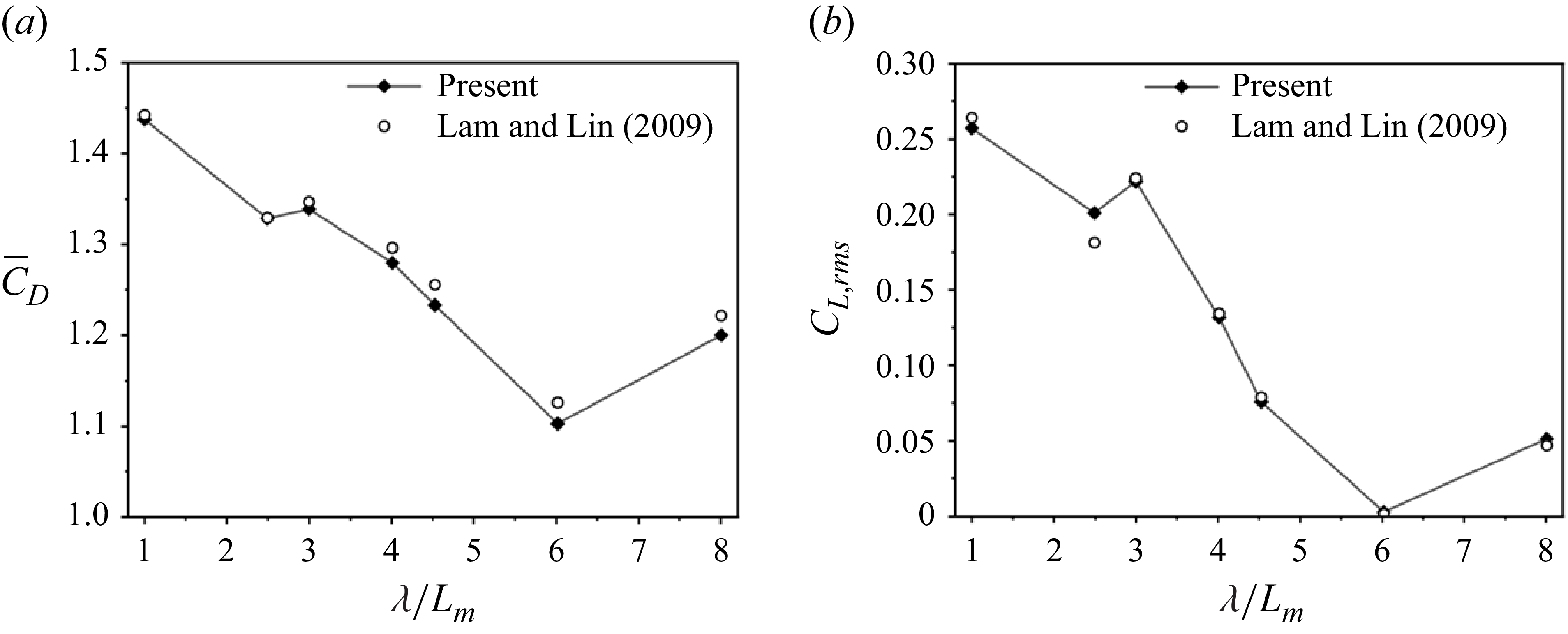
Furthermore, to validate the aerodynamic behaviour of the wavy cylinder (IPU) at comparable Reynolds numbers, figure 3 compares the present results with those of Lam & Lin (Reference Lam and Lin2009). Both datasets exhibit the same overall trend of decreasing mean drag (
 $\overline {C_{\!D}}$
) and lift fluctuations (
 $C_{L,rms}$
) with increasing wavelength, confirming that the present methodology accurately captures the wavelength-dependent aerodynamic response of wavy cylinders.
Comparison of (a) time-averaged drag coefficient (
 $\overline {C_{\!D}}$
) and (b) root-mean-square lift coefficient (
 $C_{L,rms}$
) between the present results and Lam & Lin (Reference Lam and Lin2009) for the wavy cylinder (IPU) at Re = 100.

3. Results and discussions
3.1. Topology transformation from 2-D to 3-D vortical structures
Understanding the transformation of flow from 2-D to 3-D is crucial for designing more efficient fluid-interactive structures, as it provides insights that help reduce drag and control flow separation. As 2-D vortices transition into 3-D structures, they evolve into complex patterns like vortex rings and hairpin vortices, which significantly impact flow behaviour. Therefore, analysing how flow structure transforms from 2-D to 3-D across various undulation axes is essential to fully understand these complex behaviours. In undulated cylinders, 3-D vortical structures emerge from modifications in the original 2-D spanwise vortical structure. To better understand this transformation, we analyse and visualise these 3-D vortical structures, along with the streamlines in the spanwise planes, across different undulated cylinder configurations. Two distinct counter-rotating vortices (one in the upper and one in the lower wake region) are observed behind the cylinder, where the term counter-rotating refers to the instantaneous coexistence of opposite-sense vortex cores rather than temporally alternating vortex shedding
3.1.1. Transformation of spanwise vortices
In a smooth circular cylinder at the same Reynolds number, only 2-D spanwise vortex tubes exist. However, in undulated cylinders, the introduction of cross-sectional variations leads to significant changes in vortex behaviour, triggering the transformation from 2-D to 3-D structures. This transformation is strongly influenced by wavelength and the spatial arrangement of bluff and streamlined regions along the span.
The transformation of spanwise vortices in undulated cylinders is analysed using the
 $\lambda _2$
method proposed by Jeong & Hussain (Reference Jeong and Hussain1995), as shown in figures 4–11. Additionally, overlaid spanwise vortex contours and streamline visualisations have been widely used as key indicators for distinguishing flow patterns (Lam & Lin Reference Lam and Lin2007, Reference Lam and Lin2009; Nam & Yoon Reference Nam and Yoon2022; Yoon et al. Reference Yoon, Nam and Kim2022; Shi et al. Reference Shi, Bai, Alam, Ji and Zhu2023). All visualisations in figures 4–11 are obtained from instantaneous flow fields after the simulations reached statistically steady states. The computational domain spans two wavelengths (
 $2\lambda$
) in the spanwise direction with periodic boundary conditions, but only one representative wavelength (
 $0 \leq z/\lambda \leq 1$
) is visualised for clarity, since the flow structures repeat periodically along the span.
-
(A) Short-wavelength effects (SU, TU, APU)
Three-dimensional vortex structures and in-plane flow fields of the SU cylinder for
 $\lambda /L_m=2.5$
. (a) Iso-surfaces of vortical structures identified using the
 $\lambda _2$
criterion (Jeong & Hussain Reference Jeong and Hussain1995), viewed from the top and bottom, coloured by spanwise vorticity (
 $\omega _z$
). (b–d) Streamlines in
 $x$
–
 $y$
planes at selected spanwise locations: (b) node
 $z/\lambda =0.0$
; (c)
 $z/\lambda =0.3$
; and (d) saddle
 $z/\lambda =0.5$
. The upper and lower vortex cores (
 $V_{{U}}$
and
 $V_{{L}}$
) are annotated.

Three-dimensional vortex structures and in-plane flow fields of the TU cylinder for
 $\lambda /L_m=2.5$
. (a) Iso-surfaces of vortical structures identified using the
 $\lambda _2$
criterion (Jeong & Hussain Reference Jeong and Hussain1995), viewed from the top and bottom, coloured by spanwise vorticity (
 $\omega _z$
). (b–d) Streamlines in
 $x$
–
 $y$
planes at selected spanwise locations: (b) node (
 $z/\lambda =0.0$
); (c)
 $z/\lambda =0.4$
; and (d) saddle (
 $z/\lambda =0.5$
). The upper and lower vortex cores (
 $V_{{U}}$
and
 $V_{{L}}$
) are annotated.

In the SU configuration, where the undulation aligns with the streamwise direction, the transition from a 2-D to a 3-D vortical structure is of particular significance. As the spanwise wavelength increases, secondary vortex components develop in directions other than the spanwise axis, gradually altering the originally 2-D spanwise vortex system. This transformation strongly affects vortex formation and its spanwise evolution.
At a representative short wavelength of
 $\lambda /L_m=2.5$
, this transformation is clearly visualised in figure 4(a), where the 3-D vortical structures are overlaid with spanwise vorticity contours. Two distinct counter-rotating vortices of an upper vortex (
 $V_{{U}}$
) and a lower vortex (
 $V_{{L}}$
) are observed with high intensity. However, near the nodal planes (
 $z/\lambda =0.0$
), where the cross-section is more streamlined, both vortices are notably weakened or nearly vanish, as shown in figure 4(b). As the spanwise position approaches the saddle planes (
 $z/\lambda =0.3\sim 0.5$
), where the cross-section becomes bluffer, the vortices begin to form (figure 4
c) and further develop in strength and size (figure 4
d). As a result, 2-D spanwise vortex tubes deform and reorganise into 3-D structures: they are nearly absent at the nodes, whereas towards the saddle points, they grow larger, bend and form a series of conical structures aligned in the streamwise direction, as shown in figure 4(a).
In contrast, the TU configuration exhibits a transverse wave pattern, where bluff regions are positioned at the nodes (
 $z/\lambda =0.0$
) and streamlined regions at the saddles (
 $z/\lambda =0.5$
). This configuration results in cross-sectional variations perpendicular to the flow. As shown in figure 5(a), flow acceleration at the streamlined saddle points weakens vortex strength, leading to the dislocation of the upper spanwise vortex (
 $V_{{U}}$
) and a reduction in the lower vortex (
 $V_{{L}}$
). In contrast, at bluff nodes, where flow separation is more pronounced, vortex formation remains strong, as illustrated in figure 5(b). Towards the saddle regions (
 $z/\lambda =0.5$
), vortices become small and weak (figure 5
c) and eventually disappear (figure 5
d).
The observed vortex behaviour primarily arises from the relative positioning of bluff and streamlined regions, rather than the wave orientation itself. In particular, SU and TU configurations exhibit an anti-phase relationship, where the positions of bluff and streamlined regions are inverted. This structural contrast strongly influences vortex formation and development, suggesting that the spatial arrangement of these regions governs vortex positioning, as visualised in the 3-D vortical structures and streamline results.
Three-dimensional vortex structures and in-plane flow fields for the APU cylinder at
 $\lambda /L_m=2.5$
. (a) Iso-surfaces of vortical structures identified using the
 $\lambda _2$
criterion (Jeong & Hussain Reference Jeong and Hussain1995), viewed from the top and bottom, coloured by spanwise vorticity (
 $\omega _z$
). (b–g) In-plane streamlines in
 $x$
–
 $y$
planes at representative spanwise locations: (b) node (
 $z/\lambda =0.0$
); (c)
 $z/\lambda =0.1$
; (d)
 $z/\lambda =0.2$
; (e)
 $z/\lambda =0.3$
; ( f)
 $z/\lambda =0.38$
; and (g) saddle (
 $z/\lambda =0.5$
). The upper and lower vortex cores (
 $V_{{U}}$
and
 $V_{{L}}$
) are indicated.

Unlike SU and TU, where vortex structures change gradually along the span, APU shows a more dynamic transformation, characterised by strong vortex dislocation and localised vortex formation, as shown in figure 6. Here,
 $V_{{L}}$
forms an inverted bow shape (figure 6
a), reaching its maximum size at the saddle (
 $z/\lambda =0.5$
), where the bluff cross-section enhances flow separation. Meanwhile,
 $V_{{U}}$
appears only within a short spanwise range, but is gradually suppressed as
 $V_{{L}}$
expands. Near the node (
 $z/\lambda =0.0$
),
 $V_{{L}}$
diminishes as the streamlined shape stabilises the flow. Streamline patterns (figure 6
b–g) illustrate this transformation, showing the absence of vortices at the streamlined node (figure 6
b). As the flow moves towards the saddle,
 $V_{{L}}$
emerges and grows, contributing to reverse flow due to increased pressure at the bluff saddle (figure 6
f–g). At an intermediate circular cross-section,
 $V_{{U}}$
appears briefly (figure 6
d) before detaching (figure 6
e). Closer to the saddle,
 $V_{{L}}$
expands, ultimately suppressing and eliminating
 $V_{{U}}$
(figure 6
f). This transformation underscores the role of bluff and streamlined region positioning in governing the temporal evolution of vortex structures along the span.
-
(B) Long-wavelength effects (SU, TU, APU)
At long wavelengths, a phase difference in vortex onset arises, leading to significant spanwise interactions between vortices. Vortices generated on different spanwise planes influence downstream flow on other planes and interact with each other. In this process, some vortices form earlier while others appear later, creating a scenario where vortices from one spanwise plane coexist with those from other planes in the downstream flow.
Three-dimensional vortex structures and in-plane flow fields of the SU cylinder at
 $\lambda /L_m = 8.0$
. (a) Iso-surfaces of vortical structures identified using the
 $\lambda _2$
criterion (Jeong & Hussain Reference Jeong and Hussain1995), viewed from the top and bottom, coloured by spanwise vorticity (
 $\omega _z$
). (b–g) Streamlines in
 $x$
–
 $y$
planes at selected spanwise locations: (b) saddle (
 $z/\lambda =0.5$
); (c)
 $z/\lambda =0.4$
; (d)
 $z/\lambda =0.28$
; (e)
 $z/\lambda =0.22$
; ( f)
 $z/\lambda =0.12$
; and (g) node (
 $z/\lambda =0.0$
). Labelled vortex cores (
 $V_{{U}1}$
–
 $V_{{U}3}$
,
 $V_{{L}1}$
–
 $V_{{L}3}$
) indicate progressive development and interaction of upper and lower vortices along the span.

In the SU configuration, spanwise vortex interactions align both upper and lower vortical structures downstream, with larger and stronger vortices forming near the saddle (
 $z/\lambda =0.5$
). As the flow progresses towards the node (
 $z/\lambda =0.0$
), these structures gradually decrease in size and strength, as illustrated in figure 7(a). The vortical structure tilts towards the nodes, becoming narrower and more pointed as it moves downstream.
Figure 7(b–g) confirm that these vortical structures are strongly influenced by spanwise vortex interactions. Vortex labels (
 $V_{{L}1}$
,
 $V_{{L}2}$
and
 $V_{{U}1}$
) follow the downstream order of appearance at the given instant. Slight asymmetry between upper and lower vortices arises from local phase shifts induced by spanwise undulation. The saddle point (
 $z/\lambda =0.5$
), which exhibits broad formations, generates large upper (
 $V_{{L}1}$
) and lower(
 $V_{{U}1}$
) vortices nearly simultaneously, meaning that both cores reach comparable phases of development within the same shedding cycle rather than at exactly the same instant, due to the geometric influence of the undulated edges (figure 7
b). As the flow transitions from the saddle towards the node, the transverse width of the spanwise plane decreases and smooths out. This change causes the initially elongated vortex to split into smaller vortices (
 $V_{{U}1}$
and
 $V_{{U}2}$
) in the streamwise direction as observed along the spanwise variation, representing spatial fragmentation rather than temporal shedding, as depicted in figure 7(c). As the streamwise length increases, vortices gradually weaken (figure 7
d–e) until they fully dissipate at specific spanwise locations (figure 7
f).
The decay of counter-rotating vortices results from momentum and vorticity transfer, which can deform, merge or break up vortices (Crow & Champagne Reference Crow and Champagne1971). Velocity gradients also stretch vortices, decreasing their strength over time (Pope Reference Pope2001).
Approaching the node (
 $z/\lambda =0.0$
), the flow becomes more oscillatory, causing vortices (
 $V_{{L}3}$
and
 $V_{{U}3}$
) to reappear in figure 7(g). This oscillatory nature supports the reformation of vortices, illustrating the complex interplay of flow structures in downstream evolution.
Three-dimensional vortex structures of (a) TU and (b) APU cylinders at
 $\lambda /L_m = 8.0$
, visualised by iso-surfaces of vortical structures identified using the
 $\lambda _2$
criterion (Jeong & Hussain Reference Jeong and Hussain1995) and coloured by spanwise vorticity (
 $\omega _z$
).

Figure 8 presents the 3-D vortex structures for the TU and APU configurations. In the TU case (figure 8
a), vortices primarily form near the nodal plane (
 $z/\lambda =0.0$
), where the cross-section is most bluff. These structures converge and taper downstream towards the saddle region (
 $z/\lambda =0.5$
), exhibiting a narrowing trend opposite to that of SU.
In contrast, the APU configuration (figure 8 b) generates stronger and larger vortices near the saddle region. These vortical structures align downstream along both upper and lower sides, but gradually diminish in size and intensity towards the node. This trend resembles that of the SU case, although the vortices in APU are more pronounced near the saddle.
Overall, the TU configuration exhibits an inverted spanwise behaviour compared with SU, whereas APU displays a flow evolution more similar to SU. Due to this similarity, only 3-D vortex structures are presented here, as in-plane streamlines would offer limited additional insight beyond those already discussed for SU.
-
(C) Short- versus long-wavelength vortex behaviour
At short wavelengths, spanwise vortices originate from bluff regions and extend in an almost continuous manner. However, as the cross-section gradually transitions into a more streamlined shape, these vortices weaken and eventually vanish. In contrast, at long wavelengths, vortical structures become more dislocated and are confined within localised bluff regions along the span. Consequently, vortical structures at longer wavelengths exhibit greater spatial confinement compared with those at shorter wavelengths, leading to distinct variations in vortex onset and evolution.
Three-dimensional vortex structures and in-plane flow fields for the IPU cylinder at
 $\lambda /L_m=4.5$
. (a) Iso-surfaces of vortical structures identified using the
 $\lambda _2$
criterion (Jeong & Hussain Reference Jeong and Hussain1995), viewed from the top and bottom, coloured by spanwise vorticity (
 $\omega _z$
). (b–d) In-plane streamlines in
 $x$
–
 $y$
planes at representative spanwise locations: (b) node (
 $z/\lambda =0.0$
); (c)
 $z/\lambda =0.4$
; and (d) saddle (
 $z/\lambda =0.5$
). The upper and lower vortex cores (
 $V_{{U}}$
,
 $V_{{L}1}$
and
 $V_{{L}2}$
) are indicated.

At long wavelengths, vortex formation follows two distinct mechanisms. First, wake-induced vortex formation occurs due to flow separation from the surface, generating vortices near the wake. Second, bluffness-induced vortex formation takes place away from the surface at locations where bluffness is most pronounced along the spanwise plane. The coexistence of these two formation mechanisms introduces a phase delay of vortex onset, a defining characteristic of long-wavelength undulated flows. Unlike short wavelengths, where vortex formation is synchronous and continuous, long wavelengths induce asynchronous vortex generation, leading to complex 3-D interactions between vortices at different spanwise locations. This phase delay causes vortices at different spanwise positions to develop at different rates, leading to complex wake interactions unique to long-wavelength flows.
-
(D) Vortex structure of IPU.
In contrast to SU, TU and APU configurations, which feature significant spanwise variation in vortex development, the IPU configuration, defined by a circular cross-section with in-phase undulation, demonstrates a more coherent and stabilised vortex shedding behaviour. At
 $\lambda /L_m=4.5$
, where 3-D effects become apparent, the wake maintains a spanwise phase-shifted shedding pattern, as illustrated in figure 9. Unlike elliptical cross-section configurations, which undergo noticeable transitions depending on wavelength, the IPU configuration exhibits consistent vortex behaviour across the span. Therefore, it is presented as a representative case rather than being assigned to short- or long-wavelength regimes.
As shown in figure 9(a–d), alternating upper (
 $V_{{U}}$
) and lower (
 $V_{{L}1}$
and
 $V_{{L}2}$
) vortices appear along the spanwise direction, forming a staggered shedding pattern. Here,
 $V_{{L}1}$
and
 $V_{{L}2}$
denote successive vortical structures rather than distinct vortex types, and their appearance reflects the spatial progression of spanwise phase delay in vortex roll-up. The reduced deformation in the circular cross-section contributes to more uniform vortex generation and suppresses excessive distortion or breakdown of the shedding pattern.
These observations indicate that the geometric isotropy of the circular cross-section of the IPU helps preserve spatial coherence in the wake and promotes a more stable 3-D vortex structure. The result is a robust, phase-shifted shedding behaviour with minimised lateral vortex dislocation, emphasising the stabilising role of circular in-phase undulations in passive flow control strategies.
3.1.2. Onset of streamwise and transverse vortices
In smooth cylinders at low Reynolds numbers, only 2-D spanwise vortices are present. In contrast, in undulated cylinders, geometric disturbances alter the natural flow path, generating additional streamwise and transverse vortices. These vortices interact with existing spanwise vortices, modifying their structure and leading to fully 3-D vortical patterns. This transformation highlights the role of undulated geometries in shaping vortex evolution and wake dynamics. This study provides direct visualisation of these additional vortices, offering new insights into their formation, interaction and influence on overall vortex behaviour.
Three-dimensional vortex structures at short wavelengths (
 $\lambda /L_m=2.5$
), visualised by iso-surfaces of vortical structures identified using the
 $\lambda _2$
criterion (Jeong & Hussain Reference Jeong and Hussain1995) and coloured by (a,c,e,g) streamwise vorticity
 $\omega _x$
and (b,d, f,h) transverse vorticity
 $\omega _y$
, with overlaid streamlines. Results are shown for: (a,b) SU; (c,d) TU; (e, f) APU; and (g,h) IPU cylinders.

At short wavelengths, vortices maintain a relatively continuous structure (figure 10). Streamwise vortices form along the undulation edges, while transverse vortices appear near the nodes. The SU configuration generates strong streamwise vortices at conical edges in the
 $y$
–
 $z$
plane (figure 10
a) and transverse vortices at nodes in the
 $x$
–
 $z$
plane (figure 10
b). The TU configuration, with its opposite wave direction, concentrates streamwise vortices around nodal planes (figure 10
c), while transverse vortices are significantly weakened or absent (figure 10
d). The APU configuration, with greater spanwise variation, produces both strong streamwise and transverse vortices (figure 10
e, f), whereas the IPU configuration, characterised by a circular cross-section, generates weaker vortices with a more uniform distribution (figure 10
g,h).
These additional vortices interact with spanwise vortices, reducing their strength and spatially dislocating them, which alters vortex shedding in the wake. As the wavelength reaches a critical value, these interactions allow the flow to stabilise, transitioning into a steady-state configuration. This process demonstrates how vortex interactions influence wake coherence and stability in undulated flows.
Three-dimensional vortex structures at long wavelengths (
 $\lambda /L_m = 8.0$
), visualised by iso-surfaces of vortical structures identified using the
 $\lambda _2$
criterion (Jeong & Hussain Reference Jeong and Hussain1995) and coloured by (a,c,e,g) streamwise vorticity
 $\omega _x$
and (b,d, f,h) transverse vorticity
 $\omega _y$
, with overlaid streamlines. Results are shown for: (a,b) SU; (c,d) TU; (e, f) APU; (g,h) IPU cylinder configurations.

As wavelength increases, vortex structures become more dispersed and localised within specific bluff regions (figure 11). This phase delay leads to asynchronous vortex formation, affecting downstream wake interactions. In SU and TU configurations, vortices concentrate near saddle and node points (figure 11 a–d), forming leg-like streamwise patterns in the downstream wake. The APU configuration generates strong vortices near bluff regions (figure 11 e, f), while the IPU configuration exhibits weaker dislocation and more continuous vortex structures (figure 11 g,h).
With further wavelength increase, vortices become confined to specific regions, reducing overall three-dimensionality compared with shorter wavelengths, where vortices are widely distributed. This transition from a complex 3-D flow structure at short wavelengths to a more localised pattern at long wavelengths demonstrates how wavelength and geometric undulation modulate vortex formation and evolution.
3.2. Effect of wave orientation on vortex evolution
Wave orientation significantly influences vortex evolution in undulated cylinders, affecting both spanwise vortex dynamics and the formation of additional streamwise and transverse vortices (figures 4–11). These interactions modify vortex shedding patterns and wake coherence, leading to variations in vortex size, rotational direction and dislocation mechanisms. Vortex dislocation occurs through axis disconnection, stretching and break-up, and vortex-free zones, each contributing to localised disruptions in vortex coherence and wake dynamics. To examine these effects, vortex trajectories, spatial distributions and dislocation events are analysed, providing insight into the role of wave orientation in shaping 3-D vortex evolution. The term vortex stretching and break-up is used here to describe local spatial fragmentation of vortical cores within the same shedding state, distinguishing it from the global shedding-state bifurcation reported by Shi et al. (Reference Shi, Alam, Zhu, Ji, Bai and Sharifpur2024)
3.2.1. Spanwise vortex evolution
To systematically analyse spanwise vortex evolution, the mean flow fields are visualised using streamlines, enabling the tracking of vortex trajectories and spatial distributions at different spanwise locations.
Time-averaged streamlines in the
 $x{-}y$
plane at three spanwise positions (
 $z/\lambda =0.0$
, 0.1 and 0.5) for the (ai–aiii) SU, (bi–biii) TU, (ci–ciii) APU and (di–diii) IPU configurations at
 $\lambda /L_m = 2.5$
.

Figure 12 presents time-averaged streamlines in the
 $x{-}y$
plane for a short wavelength of
 $\lambda /L_m = 2.5$
, across three spanwise positions (
 $z/\lambda = 0.0$
, 0.1 and 0.5) for SU, TU, APU and IPU configurations. In the elliptical-section cylinders, spanwise vortices primarily form in bluff regions and gradually weaken or disappear as the cross-section transitions towards more streamlined shapes. This weakening is most evident in SU and APU, where vortex-free or weakened zones are clearly observed at specific sections. For example, in SU, the vortex is completely suppressed at the node (figure 12
ai), remains weak at
 $z/\lambda = 0.1$
(figure 12
aii) and reappears strongly at the saddle (figure 12
aiii). Similarly, in APU, vortex disappearance is observed at
 $z/\lambda = 0.0$
and 0.1 (figure 12
ci,cii), with recovery occurring at the saddle (figure 12
ciii).
In contrast, the TU configuration maintains relatively persistent vortices along the span (figure 12 bi–biii), although their strength and shape vary, reflecting the cross-sectional geometry around nodal and saddle planes. Meanwhile, the IPU cylinder, characterised by a circular cross-section and in-phase undulation, exhibits the most uniform vortex distribution across the span (figure 12 di–diii), without significant disappearance or weakening. These observations demonstrate that cross-sectional asymmetry in the elliptical-section configurations leads to localised vortex suppression, while the geometric isotropy of the IPU supports more uniform and continuous vortex generation throughout the span.
Time-averaged streamlines in the
 $x{-}y$
plane at multiple spanwise positions (
 $z/\lambda = 0.0{-}0.5$
) for the (ai–aiv) SU, (bi–biv) TU, (ci–civ) APU, and (di–div) IPU configurations at
 $\lambda /L_m = 6.0$
.

For longer wavelengths, figure 13 highlights two key aspects of 3-D spanwise vortex behaviour: the coexistence mode arising from phase delays in vortex onset and the resulting dislocation of spanwise vortices due to asynchronous formation across the span. These features lead to structural irregularities in the time-averaged wake.
In the SU configuration, the streamlines reveal localised dislocations and staggered vortex appearances. For instance, a single pair of spanwise vortices is observed at the node (figure 13
ai), while certain vortex-free regions appear at
 $z/\lambda =0.16$
(figure 13
aii). Further downstream, the coexistence of multiple vortices, both upstream and downstream, is evident (figure 13
aiii), culminating in a large vortex structure at the saddle (
 $z/\lambda =0.5$
) in figure 13
aiv). The TU configuration exhibits similar features, but with a phase shift compared with SU (figure 13
bi–biv), while APU, due to greater geometric variation, shows more frequent dislocations and irregular vortex spacing (figure 13
ci–civ).
In contrast, the IPU configuration maintains continuous spanwise vortex structures across all sections, despite variations in vortex size (figure 13 di–div) without complete dislocation or absence of vortices. This uniformity suggests that the geometric isotropy of the IPU stabilises spanwise vortex development and suppresses localised disruptions.
The observed vortex evolution is classified into two stages for short wavelengths and four stages for long wavelengths, as schematically represented in figure 14 based on the vortex behaviours observed in figures 12 and 13. For short wavelengths, the vortex evolution alternates between symmetric vortex (SV) mode and no vortex zone (NV) mode, as identified in figure 12 and summarised schematically in figure 14(a). For long wavelengths, the evolution follows a four-stage process, transitioning through SV mode, vortex stretching and break-up (VSB) mode, NV mode and re-symmetric vortex (RSV) mode, as observed in figures 12 and 13, and schematically illustrated in figure 14(b).
Schematic representation of spanwise vortex evolution modes in wavy cylinders. (a) For short wavelengths (
 $\lambda /L_m = 2.5$
), alternating symmetric vortex (SV) and no vortex (NV) zones are observed. (b) For long wavelengths (
 $\lambda /L_m = 6.0$
), a four-stage evolution is identified: SV
 $\rightarrow$
vortex stretching and break-up (VSB)
 $\rightarrow$
NV
 $\rightarrow$
re-symmetric vortex (RSV).

Using these classifications in figure 14, figure 15 depicts vortex trajectories and classifications for each undulated cylinder in the
 $\lambda {-}z$
plane, showing the lower and upper limits of their presence. These maps highlight the influence of both spanwise direction and wavelength on vortex evolution, offering insights into the impact of the undulation axis on spatial vortex development. In the case of single-axis undulation, the SU configuration exhibits vortex trajectories shifted by half a wavelength along the span compared with TU, as shown in figures 15(a) and 15(b) for SU and TU, respectively. SU shows changes in spanwise vortices in response to wavelength adjustments earlier than TU, resulting in the earlier formation of an NV mode at
 $\lambda /L_m=2.5$
.
This NV mode originates from a streamlined spanwise plane and gradually extends towards bluff regions where the SV mode appears. As
 $\lambda /L_m$
increases, the spanwise vortices become more dependent on the span, reaching a critical
 $\lambda /L_m$
where the flow stabilises into a steady state. When
 $\lambda /L_m$
exceeds the critical value and reaches 6.0, various modes emerge in the half-span for the SU and TU configurations, as shown in figures 15(a) and 15(b). For SU, as the span transitions from the bluffest plane (saddle) to the streamlined plane (node), the modes appear sequentially in the order of SV, VSB, NV and RSV. In contrast, the TU configuration exhibits phase-shifted formation modes relative to SU. The VSB mode is marked by two distinct trajectories for both configurations. Beyond the VSB mode, the trajectories shift abruptly towards the surface, driven by the disappearance of vortices from the spanwise plane with the highest bluffness, as illustrated in figure 13. With a further increase in wavelength to 8.0, the SU trajectory forms a continuous line across the span, demonstrating less dependence on the spanwise direction than TU, while retaining SV mode characteristics.
The APU, with stronger 3-D dependence, generates broader NV zones (figure 15 c), and retains VSB and dislocation effects even at longer wavelengths. In contrast, IPU, with its circular cross-section, suppresses vortex dislocation due to its uniform pressure gradient, maintaining a stable SV-dominant vortex structure even at longer wavelengths (figure 15 d).
Classification maps of spanwise vortex modes across various wavelengths, plotted in the
 $\lambda /L_m{-}z/\lambda$
plane for (a) SU, (b) TU, (c) APU and (d) IPU configurations. The contours trace vortex trajectories, while coloured regions denote distinct vortex modes: symmetric vortex (SV, yellow), vortex stretching and break-up (VSB, orange dashed ellipses), no vortex zone (NV, purple) and re-symmetric vortex (RSV, green). The maps illustrate how wave orientation and wavelength jointly govern the spatial evolution and dislocation of spanwise vortices.

3.2.2. Evolution and development of streamwise and transverse vortices
The development of additional vortices due to undulated geometries is examined through transverse vortices in the
 $x{-}z$
plane (figure 16) and streamwise vortices in the
 $y{-}z$
plane (figure 17). These vortices emerge as a result of interactions between the undulated shape and the spanwise vortex structures. In the SU, transverse vortex pairs initially form farther from the transverse centre (figure 16
ai). As these vortices develop, their size increases and their centres move apart, gradually shifting towards the nodes (figure 16
aii). Eventually, these vortex pairs extend towards the transverse centre (figure 16
aiii).
In contrast, the TU exhibits transverse vortex pairs concentrated in a narrower region compared with SU, as shown in figure 16(bi–biii). The rotational and translational motion of these vortices also follows an opposite trend relative to SU. The APU, with greater geometric variation, shares characteristics with SU in terms of vortex formation range and rotational direction (figure 16
ci–ciii). Meanwhile, the IPU, due to its circular cross-section, only begins forming noticeable transverse vortex pairs at a much longer wavelength of
 $\lambda /L_m=6.0$
(figure 16
di-diii). This delayed formation highlights the role of undulation shape in transverse vortex generation.
Time-averaged streamlines in the x–z planes (1st to 3rd columns) at different
 $y/L_m$
positions for the wavy cylinders with
 $\lambda /L_m$
= 3.0, for the SU, TU and APU cylinders, and
 $\lambda /L_m$
= 6.0 for the IPU cylinder, illustrating the evolution of transverse vortices: (ai–aiii) SU; (bi–biii) TU; (ci–ciii) APU; and (di–diii) IPU.

Similarly, streamwise vortices develop in the
 $y{-}z$
plane, as shown in figure 17. Their onset and formation depend on the wavelength and wave orientation, following trends similar to transverse vortices. For a short wavelength
 $\lambda /L_m=3.0$
, the SU configuration generates relatively large and strong streamwise vortices (figure 17
ai), whereas the TU configuration produces only weak and small vortices (figure 17
bi). At a longer wavelength
 $\lambda /L_m=6.0$
, both SU and TU exhibit larger streamwise vortices (figures 17
aii and 17
bii) compared with their short-wavelength counterparts.
The APU, similar to SU, develops strong streamwise vortex pairs at both
 $\lambda /L_m=3.0$
and
 $\lambda /L_m=6.0$
, as shown in figures 17(ci) and 17(cii). However, the IPU, which does not generate noticeable streamwise vortices at
 $\lambda /L_m=3.0$
, begins forming distinct streamwise vortices at the longer wavelength (figures 17
di and 17
dii). These observations underscore the influence of undulation characteristics on the onset and development of 3-D vortical structures.
To examine the relationship between additional streamwise and transverse vortices and the resulting dimensional transition of the wake, both the vortex centre trajectories and time-averaged 3-D streamline structures are analysed. Figure 18 presents the trajectories of vortex centres in the
 $\lambda {-}z$
plane, identifying three characteristic modes: quasi-two-dimensional (Q2-D), two-dimensional spiral (2-DS), and three-dimensional spiral (3-DS). Figure 19 complements this classification by visualising the corresponding wake structures via time-averaged streamlines, confirming the spatial evolution and configuration-dependent transition of wake topology. Together, these figures provide a coherent classification framework that links wake dimensionality with undulation wavelength and orientation.
Time-averaged streamlines in the
 $y{-}z$
plane showing the development of streamwise vortices at two wavelengths
 $\lambda /L_m=3.0$
and 6.0: (ai–aii) SU; (bi–bii) TU; (ci–cii) APU; and (di–dii) IPU configurations.

The trajectories exhibit synchronised patterns across different configurations. In single-axis undulation, SU and TU configurations show opposite vortex trajectories, differing in movement direction, spanwise displacement and rotational behaviour (figures 18
a and 18
b). At a short wavelength of
 $\lambda /L_m=1$
, SU and TU first generate streamwise vortices, followed by transverse vortices, forming a quasi-2-D wake (figures 19
ai and 19
bi). Streamwise vortices span between nodes and saddles, reinforcing quasi-2-D characteristics, as observed in figures 18(a) and 18(b). As
 $\lambda /L_m$
increases to 2.5, both vortex types appear simultaneously, indicating a transition to a fully 3-D wake (figures 18
a and 18
b).
Trajectories of streamwise (red dashed lines) and transverse (black solid lines) vortices in the
 $\lambda / L_m{-}z / \lambda$
plane for (a) SU, (b) TU, (c) APU and (d) IPU configurations. The wake patterns are classified as Q2-D (quasi-2-D wake, with only streamwise vortices), 2-DS (2-D spiral wake, dominated by streamwise vortices with limited transverse components) and 3-DS (fully 3-D spiral wake, with strong interaction between streamwise and transverse vortices).

In SU, transverse vortices exhibit greater local variation than streamwise vortices within the wavelength range
 $(2.5 \leq \lambda / L_m \leq 6.0)$
. These vortices develop near the saddle and shift towards the central plane, inducing upstream and downstream flows at nodes and saddles. This alignment inclines spanwise vortices into transverse planes, generating a fully 3-D vortical structure (figure 19
aii–aiv). For
 $\lambda / L_m=4.5$
, the onset of streamwise and transverse vortices moves further downstream and vertically away from the surface, expanding their movement range (figure 18
a). This shift shortens the spanwise extension, requiring increased circulation over a wider area and supporting the formation of symmetrical planar vortex sheets (figure 19
aiii). At
 $\lambda / L_m=6.0$
, vortex coverage decreases, producing a smaller 3-D spiral flow (figure 19
aiv). When
 $\lambda / L_m=8.0$
, transverse vortices vanish, weakening wake stabilisation and reverting to a quasi-2-D wake with weak 2-D spiral flow (figure 19
av).
Time-averaged 3-D streamlines of the wake flow field for (ai–av) SU; (bi–bv) TU; (ci–cv) APU; and (di–dv) IPU configurations at five representative wavelengths
 $\lambda / L_m = 1.0, 3.0, 4.5, 6.0$
and 8.0. The wake structures are categorised as Q2-D (quasi-2-D wake with limited vortex development), 2-DS (2-D spiral wake with dominant streamwise vortices) and 3-DS (fully 3-D spiral wake with strong streamwise–transverse vortex interactions).

In TU, streamwise and transverse vortices originate above the node in blunt regions and migrate towards the streamlined saddle and transverse centre (figure 18
b), which is opposite to those observed in the SU. At shorter wavelengths, vortex formation occurs in a narrower region, with weaker intensity compared with SU (figures 18
a and 18
b for
 $\lambda / L_m=3.0$
). Consequently, TU transitions into a 3-D vortical structure later than SU, delaying wake stabilisation. At
 $\lambda / L_m=3.0$
, TU begins forming a small spiral flow near the saddle (figure 19
bii), whereas SU has already developed a fully 3-D spiral flow (figure 19
aii). For
 $\lambda / L_m=4.5$
, TU and SU exhibit similar vortex coverage (figures 18
a and 18
b), forming symmetrical planar vortex sheets (figures 19
aiii and 19
biii). At
 $\lambda / L_m=6.0$
, vortex coverage reduces (figure 18
b), leading to a smaller 3-D spiral flow (figure 19
biv). However, at longer wavelengths, the three-dimensionality of the TU wake weakens, and the flow gradually recovers a 2-D spiral shedding pattern at
 $\lambda / L_m=8.0$
(figure 19
bv). In the SU and TU configurations, the recovery of a 2-D spiral (2-DS) shedding state at large wavelengths (
 $\lambda /L_m \gt 6.0$
) arises from the weakening of spanwise coupling between crest and trough regions. As the undulation becomes gentler, spanwise phase variations diminish, enabling the wake to regain streamwise coherence and stabilise into a 2-D spiral pattern.
The APU exhibits the most significant spanwise bluffness variation, with a streamlined cross-section at the nodes and a blunter shape at the saddles. This variation forms streamwise and transverse vortices farther from the surface, increasing spatial variation (figure 18
c). Its vortex trajectories resemble SU, indicating that streamwise waviness primarily governs wake structure. APU vortices form at the bluntest saddle regions and migrate towards the streamlined nodes, persisting and coexisting over longer wavelengths with distinct 3-D trajectories. While APU forms a quasi-2-D wake at
 $\lambda / L_m=1$
(figure 19
ci), a 3-D spirally twisted vortex structure emerges for
 $(2.5 \leq \lambda / L_m \leq 8.0)$
(figure 19
cii–cv). This structure appears earlier and more prominently at
 $\lambda / L_m=3$
(figure 19
cii), producing an extended 3-D spirally twisted flow. At
 $\lambda / L_m=4.5$
and
 $6.0$
, its streamwise extent reduces due to its unsteady nature (figures 19
ciii and 19
civ). At
 $\lambda / L_m=8.0$
, the 3-D spiral wake structure remains, but becomes more confined near the rear surface (figure 19
cv).
The IPU, like SU and TU, generates only streamwise vortices at
 $\lambda / L_m = 1$
, without transverse vortices (figure 18
d), maintaining a quasi-2-D wake (figure 19
di). At
 $\lambda / L_m = 2.5$
, both vortex types appear, forming a 2-D spiral wake. In the medium wavelength range
 $(3.0 \leq \lambda / L_m \leq 4.0)$
, transverse vortices disappear, restoring quasi-2-D behaviour (figure 19
dii). For
 $\lambda / L_m = 4.5$
and
 $\lambda / L_m = 6.0$
, streamwise and transverse vortices coexist again, but remain weak, forming a 2-D spirally structured wake (figures 19
diii and 19
div). At
 $\lambda / L_m = 8.0$
, only streamwise vortices persist, simplifying the wake (figure 19
dv).
In IPU, transverse vortex generation shifts with wavelength. At short wavelengths, vortices form near the saddle and migrate towards the node, whereas at long wavelengths, they originate on the opposite side and move in the reverse direction. These shifts result from spanwise variations in separation points and vortex formation lengths (Lam & Lin Reference Lam and Lin2009). As a result, IPU generates transverse vortices over a narrower range of wavelengths than other configurations. While this limits vortex formation, it stabilises extreme wavelengths by reducing drag and lift fluctuations. However, in the medium wavelength range, intermittent transverse vortex formation enhances shedding, negatively impacting drag and lift performance.
3.3. Recirculation mechanisms and their role in wake structure
The wake closure length (
 $L_{\textit{CF}}$
) and separation points are fundamentally linked to spanwise streamlines and vortex trajectories, serving as critical indicators of how undulation type shapes wake dynamics. By focusing on
 $L_{\textit{CF}}$
and separation points, this section explores the role of recirculation mechanisms in influencing wake structure across different undulation patterns and wavelengths. Figure 20 shows the spanwise
 $L_{\textit{CF}}$
variations along with separation positions and streamlines at
 $z / \lambda = 0.0$
, 0.5, 1.0 and
 $y / \lambda = 0.5$
sections.
Variation of the recirculation length
 $L_{\textit{CF}}$
with wavelength (
 $\lambda /L_m$
) at the node (black squares) and saddle (red circles) planes for different wavy cylinder configurations: (a) SU; (b) TU; (c) APU; and (d) IPU. Embedded streamline views illustrate formation length variations, and the presence or absence of spanwise and transverse vortices, highlighting the impact of undulation geometry on wake stability and regime transitions. The separation angles at node
 $(z/\lambda = 0.0)$
and saddle
 $(z/\lambda = 0.50$
) are marked next to the cylinders, and the spanwise variation of the
 $L_{\textit{CF}}$
is shown as red solid lines in the x–z plane corresponding to the midspan section
 $(y/\lambda = 0.5)$
.

At a short wavelength of
 $\lambda / L_m = 1$
, figure 20 shows minimal spanwise variation in
 $L_{\textit{CF}}$
, with nearly identical values at node and saddle points. This uniformity indicates a quasi-2-D wake dominated by spanwise vortices. The invariant
 $L_{\textit{CF}}$
thus serves as a reliable indicator of 2-D wake behaviour under these conditions. In contrast, for
 $\lambda / L_m = 2.5$
, the
 $L_{\textit{CF}}$
becomes more sensitive to undulation type. The SU and APU show significant variation in
 $L_{\textit{CF}}$
between node and saddle points in figures 20(a) and 20(c), unlike the TU and IPU in figures 20(b) and 20(d). A distinct transition is observed, wherein the spanwise vortex at the saddle dissipates as it approaches the node, resulting in the generation of a transverse vortex and the formation of a no-spanwise vortex zone near the node, as discussed earlier in figures 12 and 13. These findings align with those of Shi et al. (Reference Shi, Bai, Alam, Ji and Zhu2023), who examined only TU-like undulated cylinders, showing that larger
 $L_{\textit{CF}}$
differences enhance wake stability in elliptical configurations by disrupting coherent vortex structures and promoting wake stabilisation.
As
 $\lambda /L_m$
increases to 4.0, SU and APU configurations induce a sharp increase in the
 $L_{\textit{CF}}$
at the blunt section (figures 20
a and 20
c), while the
 $L_{\textit{CF}}$
at streamlined sections remains minimal where no spanwise vortex zone exists. This results in a significant difference in
 $L_{\textit{CF}}$
as
 $\lambda /L_m$
increases. The transverse recirculating flow also strengthens (figures 20
a and 20
c), enhancing the stabilisation of the wake, and enabling SU and APU configurations to reach steady states at
 $\lambda /L_m=4$
more quickly than TU and IPU configurations. Shi et al. (Reference Shi, Bai, Alam, Ji and Zhu2023) support these observations in wavy elliptical cylinders, where larger
 $L_{\textit{CF}}$
differences correlate with stabilised near-wake flow patterns and reduced vortical structures.
For the TU configuration, transverse recirculating flow begins to appear at longer wavelengths (4.0 and 4.5, as shown in figure 20
b), leading to an increased
 $L_{\textit{CF}}$
difference and flow stabilisation. At
 $\lambda /L_m=6.0$
, the
 $L_{\textit{CF}}$
shortens for SU, TU and APU, and the transverse recirculating flow weakens, as shown in figure 20(a–c), causing the flow to return to an unsteady state, although a 3-D vortical structure remains present in the wake. Shi et al. (Reference Shi, Bai, Alam, Ji and Zhu2023) also report a correlation between shorter
 $L_{\textit{CF}}$
and reduced stability.
Unlike the elliptical cross-section configurations, the IPU configuration with a circular cross-section does not develop transverse recirculating flow at the
 $y/\lambda = 0.50$
plane across the wavelengths studied, even
 $\lambda /L_m = 6.0$
, where the
 $L_{\textit{CF}}$
difference between node and saddle is maximised, as shown in figure 20(d). Therefore, the IPU configuration does not achieve a fully steady state at longer wavelengths and studied amplitudes. For wavy circular cylinders (Lam & Lin Reference Lam and Lin2008, Reference Lam and Lin2009; Lin et al. Reference Lin, Bai, Alam, Zhang and Lam2016), the
 $L_{\textit{CF}}$
difference increases at longer wavelengths, where flow stabilisation is observed. In contrast, wavy elliptical cylinders exhibit the most significant effects and the largest
 $L_{\textit{CF}}$
difference within the medium wavelength range, as shown in figure 20(a–c), which is consistent with the findings of Shi et al. (Reference Shi, Bai, Alam, Ji and Zhu2023).
Finally, as
 $\lambda /L_m$
reaches its maximum value of 8 in this study,
 $L_{\textit{CF}}$
differences decrease significantly for SU, TU and IPU configurations, as shown in figure 20. However, the APU configuration, characterised by the highest spanwise gradient, maintains a pronounced
 $L_{\textit{CF}}$
difference at
 $\lambda /L_m=8.0$
. This sustained
 $L_{\textit{CF}}$
difference contributes to the generation of transverse recirculating flow, reinforcing stability. At
 $\lambda /L_m=8.0$
, APU supports a 3-D spiral wake structure in figure 19(cv), while SU, TU and IPU exhibit quasi-2-D structures without transverse recirculating flow, as illustrated in figures 19(av), 19(bv) and 19(dv).
Across all studied undulation patterns and wavelengths, recirculation mechanisms significantly influence wake structures by modulating vortex formation and stabilisation dynamics. At shorter wavelengths, wake dynamics are primarily governed by spanwise vortices, resulting in quasi-2-D structures. In contrast, medium wavelengths introduce transverse recirculating flows, enhancing wake stabilisation through alternating transverse velocity regions and upstream-downstream interactions near vortex centres. For longer wavelengths, SU and APU configurations sustain pronounced transverse recirculating flows and maintain stability, while TU and IPU configurations exhibit delayed or weaker stabilisation effects. These findings highlight the critical interplay between undulation geometry and wake dynamics, offering insights into flow control strategies for various configurations. Overall, the recirculation mechanisms, particularly the transverse recirculating dynamics and
 $L_{\textit{CF}}$
variations, serve as essential factors in determining wake stability and 3-D flow structures.
Figure 21 further examines the influence of transverse vortices on spanwise vortex modes, building on the classifications in figure 14. The SU configuration is analysed for
 $\lambda /L_m=3.0$
and
 $\lambda /L_m=6.0$
as representative short and long wavelengths. In both cases, the saddle exhibits earlier separation than the node (figure 21
a–b). This early spanwise vortex induces strong reverse flow, resembling an impinging jet on the rear surface. After impingement, the flow redirects towards the node, producing strong spanwise motion along the rear surface.
At
 $\lambda /L_m=3.0$
, this spanwise flow reaches the node, interrupting the local spanwise reverse flow (figure 21
a). This prevents spanwise vortex formation near the node, leading to the suppression of spanwise vortices in adjacent planes. Consequently, symmetric spanwise vortices (SVs) form at the saddle, but gradually vanish towards the node, resulting in the no-spanwise vortex (NV) mode in the nodal plane.
Schematic representation of transverse recirculating flows and their influence on spanwise vortex modes in the SU configuration at (a)
 $\lambda /L_m=3.0$
and (b)
 $\lambda /L_m=6.0$
. The diagrams illustrate how impingement, redirection and sweeping of transverse flows affect spanwise vortex structures, including the suppression of vortex formation (NV), emergence of symmetric vortices (SV), vortex stretching and break-up (VSB) and re-symmetric vortex (RSV) transitions.

In contrast, at the long wavelength of
 $\lambda / L_m = 6.0$
, transverse vortices are larger, but do not span the full wake width (figure 21
b). Viscous effects along the rear surface and pressure redistribution further constrain transverse vortex evolution. Near the saddle, symmetric spanwise vortices (SVs) initially appear. However, as the flow moves towards transverse vortex centres, vortex stretching and break-up (VSB) occurs, causing axis discontinuities and multiple vortex formations. At transverse vortex boundaries, streamwise flow interrupts the spanwise reverse flow, producing the NV mode. Closer to the node, symmetric vortices reform, transitioning into re-symmetric vortex mode (RSV) (figure 21
b). These findings demonstrate that transverse recirculating flows not only modify vortex interactions, but also contribute to wake stabilisation.
3.4. Force analysis
3.4.1. Critical wavelength and transition to steady flow
The aerodynamic performance of undulated geometries is strongly influenced by the transition of wake structures as
 $\lambda / L_m$
increases. Figure 22 shows that the time-averaged drag coefficient (
 $\overline {C_{\!D}}$
) and root-mean-square lift coefficient (
 $C_{L,\textit{rms}}$
) follow similar trends for undulated cylinders with elliptical cross-sections (SU, TU and APU), reflecting the evolution of wake structures and their time-dependent behaviour. The critical wavelength
 $\lambda _C/L_m$
represents the threshold beyond which wake stabilisation occurs, significantly reducing force fluctuations. As
 $\lambda / L_m$
increases, the wake transitions from a quasi-2-D spanwise vortical structure to a 3-D spiral flow, suppressing spanwise vortex shedding and unsteady aerodynamic forces. However, the onset of this transition varies with undulation type.
For SU and APU, the wake initially exhibits a quasi-2-D spanwise vortical structure at
 $\lambda / L_m = 1$
, transitions to a 3-D spiral flow at
 $\lambda / L_m = 2.5$
and stabilises at
 $\lambda _C / L_m = 4$
. This earlier transition results in a rapid reduction of
 $\overline {C_{\!D}}$
and
 $C_{L,\textit{rms}}$
. In contrast, TU undergoes a more gradual transition, maintaining a quasi-2-D spanwise vortical flow up to
 $\lambda / L_m = 2.5$
, forming a 2-D spiral flow at
 $\lambda / L_m = 3$
and finally reaching a 3-D spiral wake at
 $\lambda _C / L_m = 4.5$
. This delayed transition leads to prolonged force fluctuations compared with SU and APU.
The formation of 3-D spiral wake structures at
 $\lambda _C/L_m$
coincides with a sharp reduction in both drag and lift fluctuations. As the wake shifts from quasi-2-D to 3-D flow,
 $\overline {C_{\!D}}$
decreases significantly, particularly for SU and APU, which achieve steady wake conditions earlier than TU. Similarly,
 $C_{L,\textit{rms}}$
rapidly declines, reaching near-zero values before
 $\lambda _C / L_m$
, a direct consequence of suppressed spanwise vortex shedding.
Notably, SU maintains a steady flow state even at
 $\lambda _C / L_m = 4.5$
, highlighting its ability to sustain wake stability beyond its critical wavelength. The earlier transition of SU and APU to 3-D spiral flow compared with TU suggests that streamwise undulations play a more significant role in wake stabilisation and force coefficient reduction. These findings highlight the transition from 2-D to 3D wake structures as a key mechanism for improving aerodynamic performance in undulated geometries, emphasising the role of undulation-induced vortex structures in minimising aerodynamic forces.
3.4.2. Drag and lift characteristics beyond the critical wavelength
For
 $\lambda / L_m \gt \lambda _C / L_m$
,
 $\overline {C_{\!D}}$
exhibits distinct trends depending on the undulation type. For SU,
 $\overline {C_{\!D}}$
remains nearly constant for
 $\lambda _C / L_m \lt \lambda / L_m \leq 6$
, as shown in figure 22(a), indicating a sustained aerodynamic advantage due to the persistence of 3-D spiral flow structures, which effectively suppress vortex shedding. However, beyond
 $\lambda / L_m = 6$
,
 $\overline {C_{\!D}}$
increases sharply as the wake transitions from a 3-D spiral flow to a 2-D spiral flow, weakening flow control and increasing drag. In contrast, the TU exhibits a continuous increase in
 $\overline {C_{\!D}}$
for
 $\lambda / L_m \gt \lambda _C / L_m$
, as seen in figure 22(a). However, at
 $\lambda / L_m = 8$
, TU experiences lower
 $\overline {C_{\!D}}$
than SU, which can be attributed to the formation of a stronger 2-D spiral flow that stabilises wake dynamics and mitigates drag fluctuations, as illustrated in figure 19(b).
Meanwhile, the APU configuration follows a different trend, where
 $\overline {C_{\!D}}$
initially increases slightly after
 $\lambda _C / L_m$
, but later stabilises, maintaining an almost constant value as
 $\lambda / D_m$
continues to increase. At
 $\lambda / L_m = 8$
, APU sustains a fully developed 3-D spiral flow structure characterised by synchronised streamwise and transverse vortices, leading to the lowest
 $\overline {C_{\!D}}$
among all undulated cylinder configurations. This result highlights the superior aerodynamic efficiency of APU at longer wavelengths.
Variation of (a) time-averaged drag coefficient
 $\overline {C_{\!D}}$
and (b) root-mean-square lift coefficient
 $C_{L,\textit{rms}}$
with non-dimensional wavelength
 $\lambda / L_m$
for SU, TU, APU and IPU configurations. Each marker denotes the dominant wake regime – quasi-2-D (Q2-D), 2-D spiral (2-DS) or 3-D spiral (3-DS) – capturing transitions in wake structure and their correlation with aerodynamic force reduction and stabilisation behaviour.

The
 $C_{L,\textit{rms}}$
exhibits a strong correlation with wake flow structures. The formation of a 3-D spiral flow structure leads to a rapid decrease in
 $C_{L,\textit{rms}}$
, reducing it to near-zero values even before reaching the critical wavelength
 $\lambda _C / L_m$
. At
 $\lambda _C / L_m$
,
 $C_{L,\textit{rms}}$
reaches zero and for
 $\lambda / D_m \gt \lambda _C / L_m$
, it remains nearly zero as long as the 3-D spiral flow structure is sustained.
For APU,
 $C_{L,\textit{rms}}$
remains close to zero even at
 $\lambda / L_m = 8$
, indicating that the 3-D spiral flow structure persists at this wavelength, contributing to sustained wake stability. In contrast, both SU and TU exhibit a sharp increase in
 $C_{L,\textit{rms}}$
at
 $\lambda / L_m = 8$
, corresponding to a transition from a 3-D to a 2-D spiral flow.
Notably, at
 $\lambda / L_m = 8$
, TU exhibits both streamwise and transverse vortices, while SU primarily features only streamwise vortices. This structural difference results in TU displaying lower
 $C_{L,\textit{rms}}$
values than SU, as shown in figure 22(b). The presence of transverse vortices in TU disrupts the spanwise coherence of the wake, leading to a greater suppression of
 $C_{L,\textit{rms}}$
than in SU, where only streamwise vortices dominate.
However, APU exhibits the most stable aerodynamic performance by maintaining a fully developed 3-D spiral flow structure at
 $\lambda / L_m = 8$
, further reducing
 $C_{L,\textit{rms}}$
compared with TU. The key difference between TU and APU lies in vortex coupling. APU maintains a coherent helical structure of streamwise and transverse vortices, while TU’s vortices move irregularly, transitioning to a 2-D spiral flow. This distinction is evident in figure 19; this weaker coherence in TU results in a less stable wake and higher
 $C_{L,\textit{rms}}$
.
These findings highlight the crucial role of vortex interactions in governing wake stability and lift fluctuations. While TU benefits from the combined effects of streamwise and transverse vortices, SU’s reliance on streamwise vortices alone makes it more sensitive to vortex shedding dynamics. Meanwhile, APU maintains a 3-D spiral flow over a wider
 $\lambda / L_m$
range, minimising both drag and lift fluctuations, thereby demonstrating superior aerodynamic stability.
3.4.3. Force coefficients of the IPU
Unlike elliptic cross-sectional configurations (SU, TU, APU), the IPU exhibits two distinct depletion points in both
 $\overline {C_{\!D}}$
and
 $C_{L,\textit{rms}}$
, as shown in figures 22(a) and 22(b). Although this behaviour is influenced by wave amplitude, the most significant reductions in force coefficients and corresponding wake stabilisation occur near
 $\lambda / L_m = 2$
and
 $\lambda / L_m = 6$
, as reported by Lam & Lin (Reference Lam and Lin2009) and correspond to variations in wake closure length (
 $L_{\textit{CF}}$
) (figure 20).
In this study, the IPU, which features a circular cross-sectional plane, exhibits localised reductions in force coefficients at
 $\lambda / L_m = 2.5$
and
 $\lambda / L_m = 6$
. At
 $\lambda / L_m = 2.5$
, the wake transitions into a 2-D spiral flow, but reverts to a quasi-2-D structure at
 $\lambda / L_m = 3$
, causing an increase in aerodynamic forces. The most significant force reduction occurs at
 $\lambda / L_m = 6$
, where a localised 3-D spiral wake forms, enhancing stability. However, at
 $\lambda / L_m = 8$
, both
 $\overline {C_{\!D}}$
and
 $C_{L,\textit{rms}}$
increase again, indicating a transition back to a 2-D spiral flow and a loss of vortex stability. Unlike SU, TU and APU, which exhibit sustained aerodynamic benefits over a wide range of
 $\lambda / L_m$
, the IPU’s wake stabilisation is more localised and sensitive to specific wavelengths, limiting its overall aerodynamic efficiency.
4. Conclusions
This study systematically analysed how undulation-induced geometric variations transform 2-D spanwise vortices into 3-D vortical structures, revealing fundamental mechanisms of vortex formation, wake evolution and aerodynamic performance. By highlighting the intricate interactions between spanwise, streamwise and transverse vortices across different undulation configurations (SU, TU, APU, IPU) and wavelengths, this research provides new insights into how undulation geometry governs wake dynamics and force characteristics.
A key finding of this study is that undulated surfaces generate distinct 3-D vortical structures due to spanwise variations in cross-sectional geometry, affecting vortex onset, strength and stability. At short wavelengths, vortices originate from bluff regions and diminish in a continuous manner, gradually stabilising the wake along the spanwise direction. In contrast, at long wavelengths, vortical structures become highly localised, exhibiting phase differences in vortex onset across spanwise positions. Some regions experience earlier vortex formation, while others show delayed onset, leading to phase-shifted vortex interactions.
The influence of undulation orientation on vortex evolution and wake characteristics is also evident. SU induces a structured wake with faster stabilisation by confining vortices to specific bluff regions, whereas TU alters spanwise vortex alignment, prolonging wake instability. APU, with the highest spanwise variation, intensifies vortex bifurcation and localisation. IPU, with its circular cross-section, significantly delays stabilisation compared with elliptical-section cases, with its wake intermittently stabilising at specific wavelengths.
This study further revealed that undulation-induced modifications lead to the emergence of additional vortex structures, such as streamwise and transverse vortices, which influence wake organisation. At short wavelengths, streamwise vortices consistently form along the edges of undulation-induced conical regions, while transverse vortices concentrate at nodal points, reinforcing a continuous 3-D vortex structure. In contrast, at long wavelengths, these vortices become more dispersed and localised, transitioning the wake from a highly intricate 3-D structure to a more spatially confined vortex distribution. This shift highlights the role of undulation geometry in regulating vortex strength, distribution and wake stability.
The influence of undulation orientation on vortex evolution and dislocation was further clarified through a classification framework that defines distinct phases of wake transition. Initially, stable spanwise vortices (SVs) form, maintaining coherence due to uniform pressure and velocity distributions. As transverse instabilities develop, vortex stretching and break-up (VSB) occur, leading to vortex splitting, trajectory deviations and increased wake complexity. In certain regions, strong wake instabilities suppress vortex formation entirely, forming no-vortex zones (NV) that significantly alter the wake structure. As the flow evolves, wake instabilities gradually subside and vortex structures regain symmetry in the re-symmetric vortices (RSVs) stage, restoring partial wake stability. This classification provides a structured framework for analysing wake transitions in undulated cylinders and offers new criteria for evaluating vortex dynamics in complex flows. A preliminary examination of temporal velocity signals at representative downstream locations indicated that the dominant shedding frequency remains nearly identical among all configurations, with only mild local modulation introduced by the undulation. A more detailed spectral characterisation, including the spanwise variation of the dominant frequency, will be undertaken in future work to quantify frequency modulation and energy redistribution in undulated-cylinder wakes (Shi et al. Reference Shi, Alam, Zhu, Ji, Bai and Sharifpur2024).
The transverse recirculating flow was discovered as a key mechanism influencing wake stabilisation and vortex dynamics. The transverse recirculating flow alters vortex formation by generating reverse impingement near the saddle plane, induces low-pressure regions, redirects fluid towards the node and weakens spanwise vortex coherence. At short wavelengths, this effect is weak, leading to a quasi-2-D wake structure dominated by spanwise vortices. As the wavelength increases, transverse recirculating flow strengthens, disrupting spanwise coherence and promoting wake three-dimensionalisation. This influence is most pronounced in SU and APU, where strong transverse recirculating flow enhances vortex interactions and accelerates wake stabilisation. In contrast, TU and IPU exhibit weaker transverse recirculating flow, prolonging wake instabilities. At extreme wavelengths, only APU maintains a 3-D spiral wake, while SU, TU and IPU revert to a 2-D spiral structure, where wake coherence diminishes and vortex interactions weaken.
The relationship between force characteristics and wake stabilisation was strongly influenced by undulation configurations, which regulate the transition from quasi-2-D spanwise vortical flow to 3-D spiral flow. The critical wavelength
 $\lambda _C / L_m$
plays a decisive role in wake stabilisation, significantly reducing drag
 $\overline {C_{\!D}}$
and lift fluctuations
 $C_{L,\textit{rms}}$
. SU and APU stabilise earlier at
 $\lambda _C / L_m = 4$
, whereas TU undergoes a delayed transition, maintaining a quasi-2-D wake up to
 $\lambda _C / L_m = 4.5$
. Beyond this threshold,
 $\overline {C_{\!D}}$
and
 $C_{L,\textit{rms}}$
exhibit distinct behaviours across configurations, underscoring the role of vortex interactions in sustaining aerodynamic benefits. APU demonstrates the most stable performance at longer wavelengths, where synchronised streamwise and transverse vortices form a coherent helical wake, minimising drag-inducing vortex interactions.
Overall, these findings emphasise the crucial role of 2-D to 3-D wake transitions in enhancing aerodynamic performance in undulated cylinders. Suppressing spanwise vortex shedding, reorganising vortex trajectories and stabilising vortex interactions contribute to reduced drag and controlled lift forces. SU and APU stabilise the wake earlier, while TU and IPU exhibit delayed or weaker stabilisation effects. Vortex dislocation, transverse recirculating flow and wake classification provide new insights for bio-inspired propulsion and energy-efficient designs. Further research should explore the impact of undulation amplitude, cross-sectional geometry and Reynolds number on wake transitions and aerodynamic performance. It is anticipated that extending the present framework to an elliptic IPU, i.e. an in-phase undulated cylinder with a non-unity mean aspect ratio, would provide further insights into the coupled effects of baseline ellipticity and undulation-induced wake stabilisation. A deeper understanding of how
 $\textit{Re}$
affects 3-D wake onset, vortex dislocation and shedding stability will help refine flow control strategies for next-generation designs. These findings may also provide guidance for designing low-Reynolds-number aerodynamic or hydrodynamic systems that require passive flow stabilisation and energy-efficient performance.
Funding
This work was supported by the Korea Institute of Energy Technology Evaluation and Planning (KETEP) and the Ministry of Trade, Industry & Energy (MOTIE) of the Republic of Korea (No. 20224000000090) and by the National Research Foundation of Korea (NRF) grant funded by the Korea government (MSIT) through NRF-2019R1A2C1009081.
Declaration of interests
The authors report no conflict of interest.
Data availability statement
The data supporting the findings of this study are available from the corresponding author, Hyun Sik Yoon, upon reasonable request.