


1 Introduction
Unsteady and bio-inspired aerodynamics have been studied extensively, motivated by their applications to small agile drones. Research on mathematical models for vehicle design and flight controllers is ongoing, due to the challenge of representing the separated flow and the forces that a vehicle may encounter during a high-angle-of-attack manoeuvre, gust or flapping-wing motion. Here we review prior models, particularly for wings in unsteady rotation that are relevant to flapping-wing flight.
Several researchers have used potential flow theory to obtain the force and moment for the incompressible flow around a flat plate or airfoil (e.g. Ansari, Żbikowski & Knowles Reference Ansari, Żbikowski and Knowles2006a ; Xia & Mohseni Reference Xia and Mohseni2013; Yan, Taha & Hajja Reference Yan, Taha and Hajja2014). Using the Joukowski transformation to map the flow to a complex plane, the velocity potentials are calculated for the background flow and any singularities, such as vortices, introduced. The pressure is evaluated from the unsteady Bernoulli equation and the force can be calculated from the unsteady Blasius theorem (see Xia & Mohseni Reference Xia and Mohseni2013; Yan et al. Reference Yan, Taha and Hajja2014), or directly from Kelvin’s impulse theorem (Ansari et al. Reference Ansari, Żbikowski and Knowles2006a ). Eldredge & Jones (Reference Eldredge and Jones2019) suggest separately modelling the fluid-inertial or added-mass force, and the circulatory force (see also Babinsky et al. Reference Babinsky, Stevens, Jones, Bernal and Ol2016).
One type of two-dimensional (2-D) potential-flow modelling introduces point or discrete vortices at small time intervals and advects them to model the separated shear layers, e.g. their rollup into leading-edge vortices (LEVs) (Ansari et al. Reference Ansari, Żbikowski and Knowles2006a ; Xia & Mohseni Reference Xia and Mohseni2013; Eldredge & Jones Reference Eldredge and Jones2019). To solve for the unknown vortex strengths, Kelvin’s theorem coupled with conditions at the leading edge (LE) and trailing edge (TE) are enforced. The Kutta condition is typically used at the TE (see Ansari et al. Reference Ansari, Żbikowski and Knowles2006a ; Xia & Mohseni Reference Xia and Mohseni2013; Eldredge & Jones Reference Eldredge and Jones2019). Ramesh et al. (Reference Ramesh, Gopalarathnam, Granlund, Ol and Edwards2014) defined an empirically determined LE suction parameter for rounded edges, which allows non-zero suction versus a Kutta condition, to determine LEV shedding. Li & Wu (Reference Li and Wu2016) used residual vortex sheets at the LE and TE, and created maps showing the contribution of each vortex element to the plate force. Numerical methods are required to implement these discrete vortex models.
To extend this to three-dimensional (3-D) flow, for a flapping (rotating, plunging and pitching) wing Ansari et al. (Reference Ansari, Żbikowski and Knowles2006a
) and Ansari, Żbikowski & Knowles (Reference Ansari, Żbikowski and Knowles2006b
) used a blade-element approach, with several 2-D sections of constant radius across the wing span; integration of the sectional forces yields the total lift. Tip effects and spanwise flow are neglected, which is reasonable at a Reynolds number (
 $Re$
) of 160 (calculated using mean chord and mean tip speed) (Ansari et al.
Reference Ansari, Żbikowski and Knowles2006b
). Compared to an experiment, the model accuracy for the overall mean lift is 13 %, with greater deviations in peak lift, and the mean error reduces to
 ${\sim}7\,\%$
with further periodic cycles.
The inviscid 3-D unsteady vortex–lattice method (UVLM) (see Roccia et al. Reference Roccia, Preidikman, Massa and Mook2013; Nguyen et al. Reference Nguyen, Kim, Han and Han2016) is also used because of its lower computational cost and higher fidelity versus the discrete vortex method. In UVLM, the vortex structures (bound vortices, wake and LEV) are divided into small lattices of constant strength, and then the velocity field is determined by applying the Biot–Savart law to the lattices. Finally, the pressure is calculated from Bernoulli’s equation to obtain the force. The UVLM (Roccia et al. Reference Roccia, Preidikman, Massa and Mook2013) performs better than the Ansari et al. (Reference Ansari, Żbikowski and Knowles2006b ) model, which is fundamentally the 2-D version of UVLM, and works for different insect geometries and kinematics. Nguyen et al. (Reference Nguyen, Kim, Han and Han2016) further modified it to incorporate the LEV force and vortex-core growth.
Other analytical models are discussed here. For a flapping wing in hover with rotation, pitching and plunging, Żbikowski (Reference Żbikowski2002) proposed two analytical approaches for calculating the lift. One is the unsteady thin-airfoil theory of von Kármán & Sears (Reference von Kármán and Sears1938), augmented with a nonlinear correction for deforming vortex wakes to model the LEV. The other is a velocity-potential approach: either a frequency-domain method (Theodorsen Reference Theodorsen1935) or an indicial technique incorporating the Wagner function (Wagner Reference Wagner1925), in conjunction with the Polhamus (Reference Polhamus1966) LE suction model. The latter approach was modified to account for wake deformation and downwash, giving reasonable results for periodic flapping, although wing–wake interactions were not modelled (Pedersen & Żbikowski Reference Pedersen, Żbikowski and Liebe2006). Pullin & Wang (Reference Pullin and Wang2004) created a similarity solution for the spiral rollup of the LE and TE vortex sheets, for a 2-D flat plate at high angle of attack (
 $\unicode[STIX]{x1D6FC}$
) having power-law starting-flow velocities. The sheet development is dictated by the Birkhoff–Rott equation, and the results exhibit good agreement with numerical simulations. For a similar problem, Pitt Ford & Babinsky (Reference Pitt Ford and Babinsky2013) showed that the LEV and bound circulations can be estimated by the Wagner function.
For 3-D flows, Wong, Gillespie & Rival (Reference Wong, Gillespie and Rival2018) proposed a shear-layer feeding model for the LEV circulation and its spanwise advection using vorticity-containing mass. The circulation feeding-rate error is 10 % when compared with delta-wing experiments. Limacher, Morton & Wood (Reference Limacher, Morton and Wood2016) simplified the Navier–Stokes equations to predict the LEV-core streamline, which agreed well with experiments inboard of the tip. Moreover, Chen et al. (Reference Chen, Kolomenskiy, Onishi and Liu2018) developed a closed-form analytical expression for the LEV position and circulation for rotating wings with various shapes, by setting a free parameter for the spanwise vorticity transport.
Some of the models described above are too computationally expensive to be readily used for engineering design or control, and low-order models are meant to address this. The NATO AVT-202 effort (Ol & Babinsky Reference Ol and Babinsky2016) gives a 2-D low-order model for flat plates undergoing translation and pitching (see also Babinsky et al.
Reference Babinsky, Stevens, Jones, Bernal and Ol2016). It uses potential flow for the added-mass force, and a scaled Wagner function for the circulation of the LE–TE vortex dipole; the time-varying distance between the LEV and trailing-edge vortex (TEV) is approximated using a relative ‘drift’ velocity between their cores equal to half the free-stream velocity. Hemati, Eldredge & Speyer (Reference Hemati, Eldredge and Speyer2014) optimized the point-vortex strengths of the Wang & Eldredge (Reference Wang and Eldredge2013) model using high-fidelity simulation data, which yields better results. Eldredge & Darakananda (Reference Eldredge and Darakananda2015) also created a low-order 3-D model that represents the flow as a small number of large-scale closed vortex loops made of linear segments. The problem is open, but can be closed with further submodels (e.g. the Kutta condition) or empirical data to obtain the time-varying vortex strengths. Recently, Darakananda & Eldredge (Reference Darakananda and Eldredge2019) developed a 2-D model for bodies at high
 $\unicode[STIX]{x1D6FC}$
, representing the LE and TE separated shear layers as discrete vortices, but the rolled-up and shed vortices as single points. To compensate for the force change from feeding circulation to the single points, a generalization of the ‘impulse-matching’ approach (Wang & Eldredge Reference Wang and Eldredge2013) to alter the point-vortex velocities is used.
Semi-empirical low-order models include that of Mancini, Manar & Jones (Reference Mancini, Manar and Jones2015) for high-
 $\unicode[STIX]{x1D6FC}$
translating and pitching plates. The potential-flow model incorporates LEV position and strength from experiments, and the steady-state lift coefficient is used to scale down the overpredicted lift. The accuracy is within 20 % when the vortex tracking is reliable, prior to LEV dissipation. A recent paper presents a cycle-averaged semi-empirical force model for a plunging (out-of-plane rotation) and twisting wing based on an undulating wave model applied to actuator disk theory (Jiao et al.
Reference Jiao, Zhao, Shang and Sun2018). The thrust force is a simple algebraic expression, somewhat similar to the circulatory lift developed in this paper and will be discussed in § 2. Galler, Weymouth & Rival (Reference Galler, Weymouth and Rival2019) proposed a semi-empirical model for an accelerating plate based on Darwin’s drift-volume approach. They also discussed the limitations of decomposing the unsteady force into circulatory and non-circulatory components for highly separated flows during the acceleration phase.
In general, quasi-steady models use steady-state forces from experiments or computational fluid dynamics (CFD) at different instants of the wing motion to estimate the time-varying lift (see Sane & Dickinson Reference Sane and Dickinson2002; Berman & Wang Reference Berman and Wang2007; Percin & van Oudheusden Reference Percin and van Oudheusden2015). Sane & Dickinson (Reference Sane and Dickinson2002) presented a quasi-steady model and blade-element implementation for a flapping wing undergoing rotation and pitching. Lee et al. (Reference Lee, Lua, Lim and Yeo2016b
) expanded this model to a greater variety of wing kinematics and geometries by finding coefficients using curve fitting to CFD simulations; the error was generally within 10 %, but up to 20 % in some cases. Nabawy & Crowther (Reference Nabawy and Crowther2014) improved the Sane & Dickinson (Reference Sane and Dickinson2002) model by introducing a power factor
 $k=k_{ind}k_{tip}k_{flap}$
in Prandtl’s lifting line theory, to estimate the slope of the 3-D wing lift. The
 $k_{ind}$
,
 $k_{tip}$
and
 $k_{flap}$
represent the non-uniform downwash velocity, tip loss and effective flapping disk area, respectively, and can be evaluated analytically. Berman & Wang (Reference Berman and Wang2007) presented force and moment expressions based on the Navier–Stokes equations with quasi-steady models for the circulatory and viscous terms, for a flapping wing (rotation, pitch and plunge). This formulation was convenient for energy optimization and a sensitivity analysis of the parameters.
A state-space model given by Taha, Hajja & Beran (Reference Taha, Hajja and Beran2014) uses Duhamel’s principle assuming linearity of the unsteady aerodynamics around flapping wings (rotation and pitching). Stipulating an attached LEV, the static lift is found from a semi-empirical relation involving aspect ratio  and
 $\unicode[STIX]{x1D6FC}$
. Coupled with the Wagner function, the unsteady lift is calculated. To make the model low-order, the radius of gyration is taken as the representative wing length. The model error is within 13 % of the direct numerical simulation results. Lee, Choi & Kim (Reference Lee, Choi and Kim2015) developed a simple scaling law for the lift using a steady vortex-loop theory, where the LEV circulation is scaled by that around a finite-
 wing. It uses only kinematic and geometric parameters, and produces an excellent collapse of the lift data for various hovering insects. The final expression is the closest to that presented here; however, the current approach employs an unsteady physical model of the evolving wing-vortex loop.
There remains a lack of a rotating-wing model that is 3-D, unsteady, closed-form, analytical and very inexpensive. In this paper, we present a simple model having these qualities, using vortex-loop dynamics. Several researchers showed that the rotating wing produces a vortex loop containing the LEV, tip vortex (TV), TEV and root vortex (RV) (e.g. Sun & Wu Reference Sun and Wu2004; Kim & Gharib Reference Kim and Gharib2010; Ozen & Rockwell Reference Ozen and Rockwell2012b ). Substantial advances have been made in understanding vortex-loop dynamics, especially for vortex rings (see Shariff & Leonard Reference Shariff and Leonard1992). Sullivan et al. (Reference Sullivan, Niemela, Hershberger, Bolster and Donnelly2008) established straightforward relations among the vortex-ring parameters, such as velocity, radius, circulation, etc., and vortex generator. This motivated the current study to estimate the unsteady lift, which takes advantage of the coherent vortex loop produced in rotating-wing flow, avoids complications from the 3-D flow structures, yet retains key physics. The model is presented in § 2, and in § 3 we compare it to several experiments and numerical simulations.
2 Model
Here the incompressible flow of a rectangular wing rotating from rest at a fixed, high
 $\unicode[STIX]{x1D6FC}$
is modelled as a single tilted LEV–TV–TEV–RV loop. The impulse of a thin, 3-D vortex loop can be written in a simple form (Wu, Ma & Zhou Reference Wu, Ma and Zhou2006) as
 $$\begin{eqnarray}\displaystyle \boldsymbol{I}=\unicode[STIX]{x1D70C}\unicode[STIX]{x1D6E4}\boldsymbol{S}, & & \displaystyle\end{eqnarray}$$
where
 $\unicode[STIX]{x1D70C}$
is the fluid density,
 $\unicode[STIX]{x1D6E4}$
is the loop circulation and
 $\boldsymbol{S}$
is the vector surface spanned by the loop. Once the impulse is known, the net force on the wing in the vertical direction, or lift, can be calculated as
 $$\begin{eqnarray}\displaystyle & \displaystyle L=L_{in}+\unicode[STIX]{x1D70C}\frac{\text{d}}{\text{d}t}(\unicode[STIX]{x1D6E4}S_{hor}), & \displaystyle\end{eqnarray}$$
where
 $S_{hor}$
is the projection of the loop area onto the horizontal plane. The second term on the right-hand side is similar to that found in Wu et al. (Reference Wu, Ma and Zhou2006). The two contributions to the net lift are the fluid-inertial force and circulatory force. Here, assuming an infinitely thin flat-plate wing, potential flow theory (Sedov Reference Sedov1965) is used at each wing section to calculate the fluid-inertial lift per unit span. This can be integrated over the entire span to get the net fluid-inertial lift, which for a rectangular, rotating wing is (Percin & van Oudheusden Reference Percin and van Oudheusden2015)
 $$\begin{eqnarray}\displaystyle & \displaystyle L_{in}=\unicode[STIX]{x03C0}\unicode[STIX]{x1D70C}c^{2}\ddot{\unicode[STIX]{x1D6F7}}\frac{b_{t}^{2}-(b_{t}-b)^{2}}{8}\sin \unicode[STIX]{x1D6FC}\cos \unicode[STIX]{x1D6FC}, & \displaystyle\end{eqnarray}$$
where
 $\unicode[STIX]{x1D6F7}$
is the wing rotation angle,
 $\ddot{\unicode[STIX]{x1D6F7}}$
is the angular acceleration,
 $c$
is the chord,
 $b$
is the span,
 $b_{t}$
is the total span, including the root cutout or offset, and
 $\unicode[STIX]{x1D6FC}$
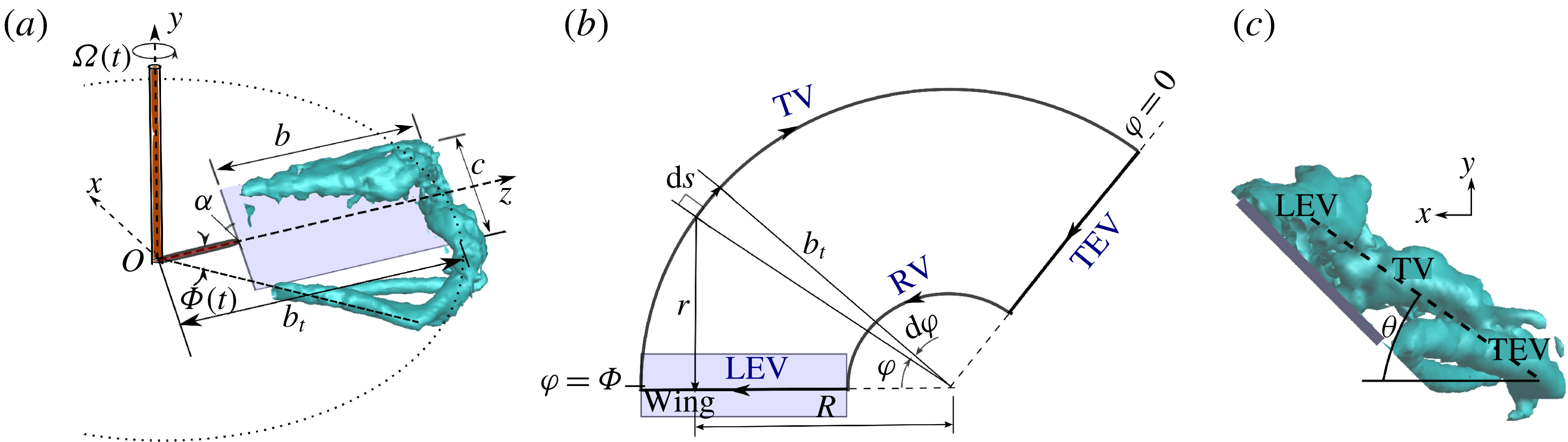
is the geometric angle of attack (figure 1
a). For the rectangular wings considered here,
 .
Figure 1(a) also shows an isosurface of the
 ${\mathcal{Q}}$
-criterion from the
 experiments of Carr, DeVoria & Ringuette (Reference Carr, DeVoria and Ringuette2015), to illustrate the real vortex flow for comparison with the model. Here the dimensionless
 ${\mathcal{Q}}^{\ast }={\mathcal{Q}}c^{2}/(R\unicode[STIX]{x1D6FA})^{2}$
is used, where
 $R$
is the radius of gyration and
 $\unicode[STIX]{x1D6FA}$
is the angular speed. A top view of the rotating-wing LEV–TV–TEV–RV loop geometry for the present model is given in figure 1(b). It is a simplification of the experiments and simulations mentioned in § 1, including that of figure 1(a). At the start of rotation,
 $\unicode[STIX]{x1D6F7}=0$
, the LEV and TEV are collocated at the span-parallel line (
 $z$
-axis), which intersects the axis of rotation, making the initial loop area zero. The
 $z$
-axis moves with the wing as
 $\unicode[STIX]{x1D6F7}(t)$
increases. It is assumed that there is a single LEV from root to tip that remains attached at this
 $z$
-axis during wing rotation, discussed further below. The TEV stays fixed at the starting angular position, which is an approximation of the behaviour found by Carr et al. (Reference Carr, DeVoria and Ringuette2015). For the model, the TV and RV formation follow the arcs traversed by the
 $z$
-axis, at their respective edge locations, starting from
 $\unicode[STIX]{x1D6F7}=0$
. Therefore, the loop shape is a circular sector growing with
 $\unicode[STIX]{x1D6F7}(t)$
, minus the root-cutout region.
(a) Schematic of the model wing and its motion, including a
 ${\mathcal{Q}}^{\ast }=6$
isosurface (Carr et al.
Reference Carr, DeVoria and Ringuette2015) to illustrate the real vortex loop. (b) Simplified vortex-loop geometry for the model (top view); the loop arrows give the swirl direction. (c) Experimental visualization to conceptually show the model loop angle (
 $\unicode[STIX]{x1D703}$
).
Piston–cylinder vortex-generator experiments have shown that the momentum imparted by the piston to the volume of fluid it displaces is nearly equal to the impulse of the vortex ring (Sullivan et al. Reference Sullivan, Niemela, Hershberger, Bolster and Donnelly2008). Drawing an analogy to the rotating-wing configuration, we assume that the angular impulse of the vortex loop about the axis of wing rotation is equal to the angular momentum of the volume of fluid brought into motion by the wing,
 $$\begin{eqnarray}\displaystyle m_{f}R^{2}\overline{\unicode[STIX]{x1D6FA}}=\unicode[STIX]{x1D70C}\unicode[STIX]{x1D6E4}S_{ver}R, & & \displaystyle\end{eqnarray}$$
where
 $m_{f}$
is the mass of this fluid, and the associated volume is approximated as the area swept through by the wing in the horizontal plane, multiplied by the projection of the wing chord onto the vertical plane,
 $$\begin{eqnarray}\displaystyle & \displaystyle m_{f}=\frac{1}{2}\unicode[STIX]{x1D70C}(c\sin \unicode[STIX]{x1D6FC})(b_{t}^{2}-(b_{t}-b)^{2})\unicode[STIX]{x1D6F7}. & \displaystyle\end{eqnarray}$$
In (2.4), the radius of gyration can be calculated from (2.6) for rectangular plates (Lee, Lua & Lim Reference Lee, Lua and Lim2016a ):

Similar to the mean piston speed in the momentum conservation equation of Sullivan et al. (Reference Sullivan, Niemela, Hershberger, Bolster and Donnelly2008), the running mean of the angular speed,
 $\overline{\unicode[STIX]{x1D6FA}}(t)$
, is used in (2.4), i.e. at each time the mean is calculated starting from
 $t=0$
(Gharib, Rambod & Shariff Reference Gharib, Rambod and Shariff1998):
 $$\begin{eqnarray}\displaystyle & \displaystyle \overline{\unicode[STIX]{x1D6FA}}(t)=\frac{1}{t}\int _{0}^{t}\unicode[STIX]{x1D6FA}(\unicode[STIX]{x1D70F})\,\text{d}\unicode[STIX]{x1D70F}=\frac{\unicode[STIX]{x1D6F7}(t)}{t}. & \displaystyle\end{eqnarray}$$
The
 $S_{ver}$
in (2.4) is the projection of the vortex loop area onto the vertical plane, derived later.
As mentioned above, it is assumed that the LEV stays attached along the
 $z$
-axis (or the wing) until the end of the motion. Jardin & Colonius (Reference Jardin and Colonius2018) showed that this is true approximately for a local Rossby number,
 $Ro$
, of
 $Ro=z/c<3$
, if the span is long enough to avoid nearby TV effects (see also Lentink & Dickinson Reference Lentink and Dickinson2009; Kruyt et al.
Reference Kruyt, van Heijst, Altshuler and Lentink2015). For larger
 $z/c$
, the LEV moves farther aft and interacts with the trailing tip flow. The LEV evolution depends on
 $Re$
,
 and
 $Ro$
(see Bhat et al. (Reference Bhat, Zhao, Sheridan, Hourigan and Thompson2019), who determined that these effects are best isolated using span-based definitions of
 $Re$
and
 $Ro$
), but often exhibits arch-like liftoff outboard and further LEVs forming ahead of the main one (e.g. Jardin, Farcy & David Reference Jardin, Farcy and David2012; Harbig, Sheridan & Thompson Reference Harbig, Sheridan and Thompson2013; Garmann & Visbal Reference Garmann and Visbal2014; Carr et al.
Reference Carr, DeVoria and Ringuette2015; Percin & van Oudheusden Reference Percin and van Oudheusden2015; Phillips, Knowles & Bomphrey Reference Phillips, Knowles and Bomphrey2015; Lee et al.
Reference Lee, Lua and Lim2016a
; Bhat et al.
Reference Bhat, Zhao, Sheridan, Hourigan and Thompson2019). However, the LEV remains close to the wing over much of the span and the overall flow exhibits a growing vortex loop for up to
 , albeit with complex outboard structures (Garmann & Visbal Reference Garmann and Visbal2014; Carr et al.
Reference Carr, DeVoria and Ringuette2015; Jardin & Colonius Reference Jardin and Colonius2018). Therefore, the simplified assumptions of an attached LEV and large-scale, increasing loop structure are reasonable at least for the
 values tested in § 3. Taking advantage of this,
 $S_{hor}$
is calculated as the area traversed by the
 $z$
-axis in the horizontal plane (figure 1
b):
 $$\begin{eqnarray}\displaystyle & \displaystyle S_{hor}=\frac{1}{2}(b_{t}^{2}-(b_{t}-b)^{2})\unicode[STIX]{x1D6F7}. & \displaystyle\end{eqnarray}$$
The
 $S_{hor}$
therefore increases linearly with
 $\unicode[STIX]{x1D6F7}$
, as also found by Sun & Wu (Reference Sun and Wu2004). For simplicity, the additional wing area is neglected, since including it produces a negligible change in lift. Moreover, placing the LEV at the
 $z$
-axis reduces the complexity of the Biot–Savart calculation, given below.
As shown in simulations and experiments, the vortex loop is inclined but with a complex, unsteady 3-D geometry (Sun & Wu Reference Sun and Wu2004; Carr et al.
Reference Carr, DeVoria and Ringuette2015; Jardin & Colonius Reference Jardin and Colonius2018). This is represented in the model by a single angle
 $\unicode[STIX]{x1D703}(\unicode[STIX]{x1D6F7})$
with respect to the horizontal (figure 1
c), yielding a planar loop. The
 $\unicode[STIX]{x1D703}$
is necessary to calculate
 $S_{ver}$
:
 $$\begin{eqnarray}\displaystyle & \displaystyle S_{ver}={\textstyle \frac{1}{2}}(b_{t}^{2}-(b_{t}-b)^{2})\unicode[STIX]{x1D6F7}\tan \unicode[STIX]{x1D703}. & \displaystyle\end{eqnarray}$$
From (2.4),
 $\unicode[STIX]{x1D6E4}$
can then be solved:
 $$\begin{eqnarray}\displaystyle & \displaystyle \unicode[STIX]{x1D6E4}=\frac{R\overline{\unicode[STIX]{x1D6FA}}c\sin \unicode[STIX]{x1D6FC}}{\tan \unicode[STIX]{x1D703}}. & \displaystyle\end{eqnarray}$$
Lee et al. (Reference Lee, Choi and Kim2015) give a similar expression, but for steady circulation, using a scaling law. The dynamic, 3-D nature of the real vortex loop makes it challenging to model
 $\unicode[STIX]{x1D703}$
. For simplicity, we conceptualize
 $\unicode[STIX]{x1D703}$
as being dictated by
 $\unicode[STIX]{x1D6FC}^{\ast }$
, which is
 $\unicode[STIX]{x1D6FC}$
scaled by the near-wake flow, and the angle
 $\unicode[STIX]{x1D6FC}_{i}$
produced by the induced velocity of the loop itself:
 $$\begin{eqnarray}\displaystyle & \displaystyle \unicode[STIX]{x1D703}(\unicode[STIX]{x1D6F7})=\unicode[STIX]{x1D6FC}^{\ast }-\unicode[STIX]{x1D6FC}_{i}(\unicode[STIX]{x1D6F7}). & \displaystyle\end{eqnarray}$$
The
 $\unicode[STIX]{x1D6FC}^{\ast }$
term is meant to account for the flow deflection after it passes over the wing. First, we take a reference for the deflection angle to be
 $\unicode[STIX]{x1D6FC}=\arctan (\sin \unicode[STIX]{x1D6FC}/\cos \unicode[STIX]{x1D6FC})$
, i.e. aligned with the chord line. However, prior work shows that the TE flow does not follow the chord line after it leaves the wing for all
 $\unicode[STIX]{x1D6FC}$
. For example, at large
 $\unicode[STIX]{x1D6FC}$
, such as
 $60^{\circ }$
, the TE flow deflects upwards compared to the chord line (Ozen & Rockwell Reference Ozen and Rockwell2012a
; Garmann & Visbal Reference Garmann and Visbal2014; Li, Dong & Cheng Reference Li, Dong and Cheng2017), implying a reduction of the near-wake downward flow. At smaller
 $\unicode[STIX]{x1D6FC}$
, e.g.
 $15^{\circ }$
, there is evidence that the TE flow is below this line (Jones & Babinsky Reference Jones and Babinsky2011; Li et al.
Reference Li, Dong and Cheng2017). To capture this inverse relationship of the near-wake downward flow with
 $\unicode[STIX]{x1D6FC}$
, the
 $\sin \unicode[STIX]{x1D6FC}$
is divided by the vertical deflection velocity,
 $V_{1}$
, from the wing orientation with a scaling factor
 $K$
to be determined, i.e.
 $V_{1}=KR\unicode[STIX]{x1D6FA}\sin \unicode[STIX]{x1D6FC}$
. Also, this can be thought of as accounting for the downwash from the LEV in the near-wake region. Similarly, the
 $\cos \unicode[STIX]{x1D6FC}$
is divided by the approximate horizontal velocity of the TEV,
 $V_{2}$
, in the wing-fixed frame, which is estimated to be
 $R\unicode[STIX]{x1D6FA}$
as discussed above. Effectively, this does not adjust the horizontal flow path, but achieves the desired decrease in the vertical flow deflection with increasing
 $\unicode[STIX]{x1D6FC}$
for a more physically meaningful
 $\unicode[STIX]{x1D6FC}^{\ast }$
. Overall, the expression is
 $$\begin{eqnarray}\displaystyle & \displaystyle \unicode[STIX]{x1D6FC}^{\ast }=\arctan \left(\frac{V_{2}}{V_{1}}\frac{\sin \unicode[STIX]{x1D6FC}}{\cos \unicode[STIX]{x1D6FC}}\right)=\arctan \left(\frac{R\unicode[STIX]{x1D6FA}}{KR\unicode[STIX]{x1D6FA}\sin \unicode[STIX]{x1D6FC}}\frac{\sin \unicode[STIX]{x1D6FC}}{\cos \unicode[STIX]{x1D6FC}}\right)=\arctan \left(\frac{1}{K\cos \unicode[STIX]{x1D6FC}}\right).\quad & \displaystyle\end{eqnarray}$$
The
 $K$
estimation is motivated by observations from the
 $\unicode[STIX]{x1D6FC}=45^{\circ }$
,
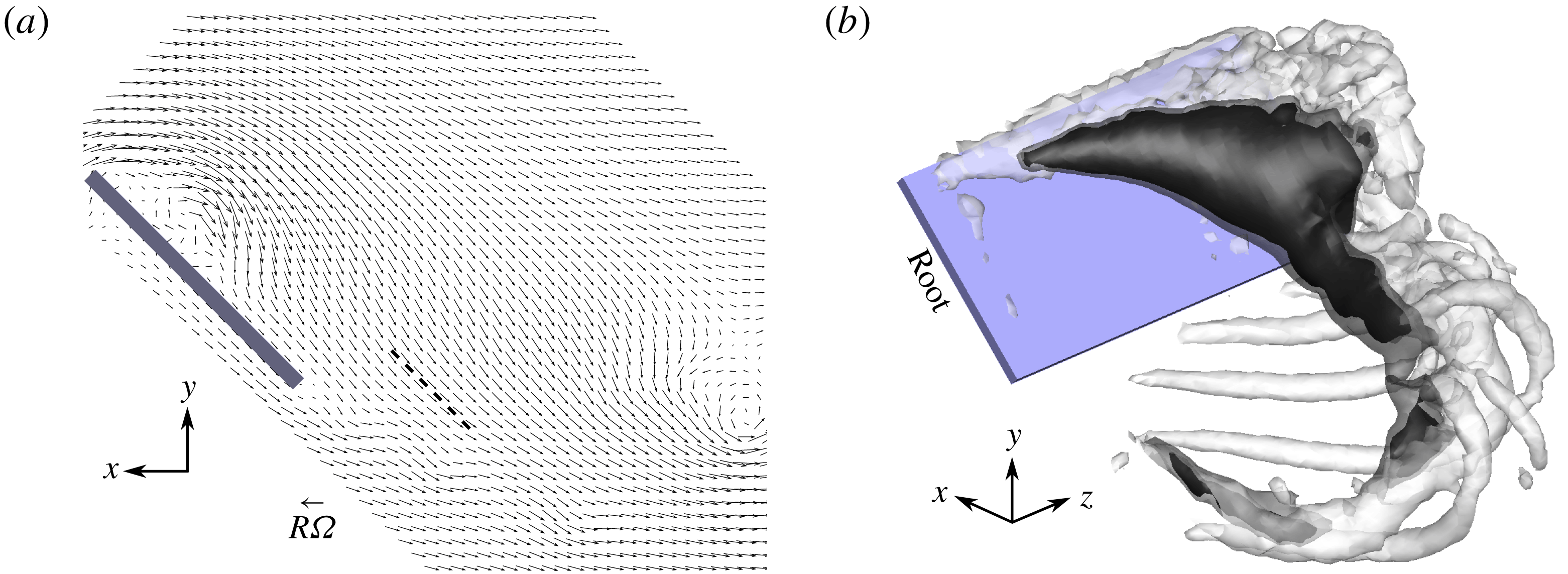
 rotating-wing data of Carr et al. (Reference Carr, DeVoria and Ringuette2015). Figure 2(a) shows velocity vectors in the rotating frame in an
 $x$
–
 $y$
plane at the radius of gyration, for
 $\unicode[STIX]{x1D6F7}=84^{\circ }$
. In the near wake, the vectors are roughly aligned with the wing chord line, as illustrated by the dashed
 $45^{\circ }$
reference line in figure 2(a), although there are local spatial variations as expected. This indicates that at
 $\unicode[STIX]{x1D6FC}=45^{\circ }$
the near-wing wake flow can be approximated as being aligned with the chord, so that
 $\unicode[STIX]{x1D6FC}^{\ast }\approx \unicode[STIX]{x1D6FC}$
. The ratio of the near-wake downward velocity to the horizontal reference velocity,
 $v/(R\unicode[STIX]{x1D6FA})$
, is visualized in three dimensions in figure 2(b) using three isosurfaces:
 $v/(R\unicode[STIX]{x1D6FA})=-1.0$
and
 $-0.9$
, and
 ${\mathcal{Q}}^{\ast }=6$
showing the vortex structure. There is a coherent region of magnitude
 $v/(R\unicode[STIX]{x1D6FA})\sim 1$
in the wake near the radius of gyration. This further suggests that the assumption of
 $\unicode[STIX]{x1D6FC}^{\ast }\approx \unicode[STIX]{x1D6FC}$
is plausible for
 $\unicode[STIX]{x1D6FC}=45^{\circ }$
. Wolfinger & Rockwell (Reference Wolfinger and Rockwell2015) also showed regions of magnitude
 ${\sim}1$
dimensionless downward velocity in the outboard flow of an
 ,
 $\unicode[STIX]{x1D6FC}=45^{\circ }$
wing for high
 $\unicode[STIX]{x1D6F7}$
and slightly larger
 $R/c$
. Therefore, the assumption of
 $\unicode[STIX]{x1D6FC}^{\ast }\approx \unicode[STIX]{x1D6FC}$
at
 $\unicode[STIX]{x1D6FC}=45^{\circ }$
leads to
 $K=\sqrt{2}$
. Although
 $K$
is estimated from observations at only
 $\unicode[STIX]{x1D6FC}=45^{\circ }$
and
 , § 3 shows that
 $\unicode[STIX]{x1D6FC}^{\ast }$
and
 $\unicode[STIX]{x1D6FC}_{i}$
yield a
 $\unicode[STIX]{x1D703}$
that allows the model to capture the correct lift trend with
 $\unicode[STIX]{x1D6FC}$
.
Experimental results from Carr et al. (Reference Carr, DeVoria and Ringuette2015) for  ,
 $\unicode[STIX]{x1D6FC}=45^{\circ }$
and
 $\unicode[STIX]{x1D6F7}=84^{\circ }$
motivating
 $\unicode[STIX]{x1D6FC}^{\ast }$
. (a) Wing-fixed
 $x$
–
 $y$
plane velocity vectors at
 $R$
along the wing span (every other vector is given); a dashed
 $45^{\circ }$
line is in the near wake for reference. (b) Isosurfaces showing magnitudes of downward velocity and the vortex loop: nested black and translucent grey indicate
 $v/(R\unicode[STIX]{x1D6FA})=-1.0$
and
 $-0.9$
, respectively; translucent white is
 ${\mathcal{Q}}^{\ast }=6$
.
The induced angle
 $\unicode[STIX]{x1D6FC}_{i}$
is given by
 $$\begin{eqnarray}\displaystyle & \displaystyle \tan \unicode[STIX]{x1D6FC}_{i}=\left|\frac{v_{i}}{U_{hor}}\right|=\frac{\unicode[STIX]{x1D6E4}A}{\left|R\overline{\unicode[STIX]{x1D6FA}}-\unicode[STIX]{x1D6E4}A\tan \unicode[STIX]{x1D703}\right|}\approx \frac{\unicode[STIX]{x1D6E4}A}{R\overline{\unicode[STIX]{x1D6FA}}}. & \displaystyle\end{eqnarray}$$
Here
 $v_{i}$
is the downward induced velocity,
 $U_{hor}$
is the net horizontal velocity at
 $R$
from the wing motion and induced by the loop, and
 $\unicode[STIX]{x1D6E4}A$
is the induced velocity of the horizontally projected loop itself;
 $A$
is what remains after
 $\unicode[STIX]{x1D6E4}$
is factored out of the Biot–Savart calculation. The denominator
 $|R\overline{\unicode[STIX]{x1D6FA}}-\unicode[STIX]{x1D6E4}A\tan \unicode[STIX]{x1D703}|$
can be approximated as
 $R\overline{\unicode[STIX]{x1D6FA}}$
, since
 $R\overline{\unicode[STIX]{x1D6FA}}\gg \unicode[STIX]{x1D6E4}A\tan \unicode[STIX]{x1D703}$
.
The
 $A$
is evaluated on the
 $z$
-axis at
 $R$
using the Biot–Savart law at each instant in time (
 $\unicode[STIX]{x1D6E4}$
is assumed constant along the loop):
 $$\begin{eqnarray}\displaystyle & \displaystyle \unicode[STIX]{x1D6E4}\boldsymbol{A}=\frac{\unicode[STIX]{x1D6E4}}{4\unicode[STIX]{x03C0}}\int _{loop}\frac{\text{d}\boldsymbol{s}\times \boldsymbol{r}}{|\boldsymbol{r}|^{3}}, & \displaystyle\end{eqnarray}$$
where
 $\text{d}\boldsymbol{s}$
is a differential length element along the loop, and
 $\boldsymbol{r}$
is the position vector from the loop to the point
 $R$
. This calculation is done for the TV, RV and TEV loop segments, and for illustration figure 1(b) gives the parameters for the TV contribution. The reference position
 $R$
is taken for
 $U_{hor}$
and the
 $A$
calculation, since it has been shown to be the most appropriate wing length scale when non-dimensionalizing and comparing flapping-wing data (Lee et al.
Reference Lee, Lua and Lim2016a
). The magnitude
 $A$
is
 $$\begin{eqnarray}\displaystyle A=A_{RV}+A_{TV}+A_{TEV}, & & \displaystyle\end{eqnarray}$$
where
 $$\begin{eqnarray}\displaystyle & \displaystyle A_{RV}=\left|\frac{1}{4\unicode[STIX]{x03C0}}\int _{0}^{\unicode[STIX]{x1D6F7}(t)}(b_{t}-b)\frac{(b_{t}-b)-R\cos \unicode[STIX]{x1D711}}{(R^{2}+(b_{t}-b)^{2}-2R(b_{t}-b)\cos \unicode[STIX]{x1D711})^{3/2}}\,\text{d}\unicode[STIX]{x1D711}\right|, & \displaystyle\end{eqnarray}$$
 $$\begin{eqnarray}\displaystyle & \displaystyle A_{TV}=\left|\frac{1}{4\unicode[STIX]{x03C0}}\int _{0}^{\unicode[STIX]{x1D6F7}(t)}b_{t}\frac{b_{t}-R\cos \unicode[STIX]{x1D711}}{(R^{2}+b_{t}^{2}-2Rb_{t}\cos \unicode[STIX]{x1D711})^{3/2}}\,\text{d}\unicode[STIX]{x1D711}\right|, & \displaystyle\end{eqnarray}$$
 $$\begin{eqnarray}\displaystyle & \displaystyle A_{TEV}=\left|\frac{1}{4\unicode[STIX]{x03C0}}\int _{0}^{b}\frac{R\sin \unicode[STIX]{x1D6F7}}{(R^{2}+(b_{t}-\unicode[STIX]{x1D6FD})^{2}-2R(b_{t}-\unicode[STIX]{x1D6FD})\cos \unicode[STIX]{x1D6F7})^{3/2}}\,\text{d}\unicode[STIX]{x1D6FD}\right|. & \displaystyle\end{eqnarray}$$
The modulus is used so the result is consistent with the actual integration path direction. The integrals are of the elliptic form, and therefore can be evaluated analytically. However, in § 3, integrals and derivatives are calculated numerically (trapezoidal rule and second-order least-squares differentiation, respectively) for convenience.
Early in the motion,
 $A_{TEV}$
(2.18) has a very high value because of the proximity of the LEV to the TEV. However, afterwards,
 $A_{TEV}$
is very small compared to
 $A_{TV}$
. Therefore, equation (2.15) is approximated as
 $$\begin{eqnarray}\displaystyle A=A_{RV}+A_{TV}. & & \displaystyle\end{eqnarray}$$
Then, substituting (2.10), (2.12), (2.13) and (2.19) into (2.11) gives
 $$\begin{eqnarray}\displaystyle & \displaystyle \sqrt{2}\cos \unicode[STIX]{x1D6FC}\tan ^{2}\unicode[STIX]{x1D703}+(Ac\sin \unicode[STIX]{x1D6FC}-1)\tan \unicode[STIX]{x1D703}+\sqrt{2}Ac\sin \unicode[STIX]{x1D6FC}\cos \unicode[STIX]{x1D6FC}=0. & \displaystyle\end{eqnarray}$$
The root of (2.20) that is physically meaningful is
 $$\begin{eqnarray}\displaystyle & \displaystyle \tan \unicode[STIX]{x1D703}=\frac{1}{2\sqrt{2}\cos \unicode[STIX]{x1D6FC}}\left[-(Ac\sin \unicode[STIX]{x1D6FC}-1)+\sqrt{(Ac\sin \unicode[STIX]{x1D6FC}-1)^{2}-8Ac\sin \unicode[STIX]{x1D6FC}\cos ^{2}\unicode[STIX]{x1D6FC}}\right].\quad & \displaystyle\end{eqnarray}$$
Later in the motion, for high
 $\unicode[STIX]{x1D6F7}$
such as
 $200^{\circ }$
(depending on the wing geometry and kinematics), the root fails and so
 $\text{d}\unicode[STIX]{x1D703}/\text{d}t$
is frozen thereafter. Once
 $\unicode[STIX]{x1D703}$
is known,
 $\unicode[STIX]{x1D6E4}$
is calculated using (2.10). Finally, the
 $\unicode[STIX]{x1D6E4}$
,
 $S_{hor}$
(2.8) and
 $L_{in}$
(2.3) are substituted into (2.2) to compute the time-varying lift. The time average of the
 $\unicode[STIX]{x1D70C}\,\text{d}(\unicode[STIX]{x1D6E4}S_{hor})/\text{d}t$
term of (2.2) yields a similar expression to that of Jiao et al. (Reference Jiao, Zhao, Shang and Sun2018) for the cycle-averaged thrust of a flapping wing (plunging and twisting) with no root gap. It should be further noted that the current model only requires the wing geometry and kinematics as inputs.
Additionally, a steady-state lift expression is developed from (2.2). Using (2.10) and (2.8), the circulatory lift component,
 $L_{circ}$
, can be written as
 $$\begin{eqnarray}\displaystyle L_{circ} & = & \displaystyle \displaystyle \unicode[STIX]{x1D70C}\frac{\text{d}}{\text{d}t}(\unicode[STIX]{x1D6E4}S_{hor})\nonumber\\ \displaystyle & = & \displaystyle \displaystyle \frac{1}{2}R\unicode[STIX]{x1D70C}c\sin \unicode[STIX]{x1D6FC}(b_{t}^{2}-(b_{t}-b)^{2})\left[\frac{2\unicode[STIX]{x1D6F7}\,\text{d}\unicode[STIX]{x1D6F7}/\text{d}t}{t\tan \unicode[STIX]{x1D703}}-\frac{\unicode[STIX]{x1D6F7}^{2}}{t^{2}\tan \unicode[STIX]{x1D703}}-\frac{\unicode[STIX]{x1D6F7}^{2}\,\text{d}\unicode[STIX]{x1D703}/\text{d}t}{t\sin ^{2}\unicode[STIX]{x1D703}}\right].\end{eqnarray}$$
At steady state,
 $\text{d}\unicode[STIX]{x1D6F7}/\text{d}t$
and
 $\unicode[STIX]{x1D6F7}/t$
can be individually equated to
 $\unicode[STIX]{x1D6FA}_{f}$
, where
 $\unicode[STIX]{x1D6FA}_{f}$
is the final steady angular speed, and
 $\text{d}\unicode[STIX]{x1D703}/\text{d}t=0$
. The steady-state value for
 $\tan \unicode[STIX]{x1D703}$
requires the steady-state value of
 $A$
, which can be determined by assuming the TV and RV to be semi-infinite in length, with circulation
 $\unicode[STIX]{x1D6E4}$
. The corresponding induced velocity due to both vortices is still calculated at
 $R$
, giving
 $A_{ss}$
as
 $$\begin{eqnarray}\displaystyle & \displaystyle A_{ss}=\frac{1}{4\unicode[STIX]{x03C0}}\left[\frac{1}{b_{t}-R}+\frac{1}{R-(b_{t}-b)}\right], & \displaystyle\end{eqnarray}$$
where the first and second terms on the right-hand side are due to the TV and RV, respectively. At steady state,
 $\tan \unicode[STIX]{x1D703}$
becomes
 $$\begin{eqnarray}\displaystyle & \displaystyle \tan \unicode[STIX]{x1D703}_{ss}=\frac{1}{2\sqrt{2}\cos \unicode[STIX]{x1D6FC}}\left[-(A_{ss}c\sin \unicode[STIX]{x1D6FC}-1)+\sqrt{(A_{ss}c\sin \unicode[STIX]{x1D6FC}-1)^{2}-8A_{ss}c\sin \unicode[STIX]{x1D6FC}\cos ^{2}\unicode[STIX]{x1D6FC}}\right]. & \displaystyle \nonumber\\ \displaystyle & & \displaystyle\end{eqnarray}$$
Finally, the steady-state values are substituted into (2.22), and
 $L_{circ}$
is non-dimensionalized by
 $1/2\unicode[STIX]{x1D70C}U_{R,f}^{2}bc$
to get the steady-state lift coefficient,
 $C_{L,ss}$
, where
 $U_{R,f}$
is the final azimuthal velocity at
 $R$
:
 $$\begin{eqnarray}\displaystyle & \displaystyle C_{L,ss}=\frac{(2b_{t}-b)\sin \unicode[STIX]{x1D6FC}}{R\tan \unicode[STIX]{x1D703}_{ss}}. & \displaystyle\end{eqnarray}$$
3 Model validation and discussion
We consider six different experimental cases to validate the model, namely  , 3 and 4 from Carr et al. (Reference Carr, DeVoria and Ringuette2015), here called UB2, UB3 and UB4, respectively, and
 with slower accelerations and varying root cutouts from Manar et al. (Reference Manar, Mancini, Mayo and Jones2016) (UMD-fast) and Percin & van Oudheusden (Reference Percin and van Oudheusden2015) (TUD). We also compare the model with the more gradual acceleration experiment of Manar et al. (Reference Manar, Mancini, Mayo and Jones2016), called UMD-slow. Additionally, we test it against the computational simulation of Phillips, Nakata & Bomphrey (found in Jones et al.
Reference Jones, Manar, Phillips, Nakata, Bomphrey, Ringuette, Percin, van Oudheusden and Palmer2016) with a motion profile and geometric parameters matching those of UMD-slow, and that of Garmann & Visbal (Reference Garmann and Visbal2014), here referred to as RVC and AFRL, respectively. The motion for the AFRL case is very gradual in the beginning, and we consider the start of the motion for the model at
 $\unicode[STIX]{x1D6F7}\approx 1^{\circ }$
. All unsteady cases tested have
 $\unicode[STIX]{x1D6FC}=45^{\circ }$
, except for AFRL with
 $\unicode[STIX]{x1D6FC}=60^{\circ }$
. Further, steady-state model results are compared with the experiments of Dickinson, Lehmann & Sane (Reference Dickinson, Lehmann and Sane1999) for various
 $\unicode[STIX]{x1D6FC}$
.
Cases for model validation.

Figure 3(a) gives the motion profiles for all unsteady cases, and table 1 provides their specific parameters. The force data were extracted from plots in the references and interpolated to a discrete time scale for all cases except the Carr et al. (Reference Carr, DeVoria and Ringuette2015) results, which were directly available. The motion profiles were generated from the equations used in the references. Figure 3(b) shows how the model loop angle
 $\unicode[STIX]{x1D703}$
varies with
 $\unicode[STIX]{x1D6F7}$
for all cases. The
 $\unicode[STIX]{x1D703}$
starts from a value equal to
 $\unicode[STIX]{x1D6FC}^{\ast }$
, then decreases rapidly and finally becomes nearly constant. All
 cases have comparable loop angles for the same
 $\unicode[STIX]{x1D6FC}$
.
(a) Motion profiles; UB2, UB3 and UB4 overlap. (b) Loop angle variation.

Comparison of the lift coefficient from the
 $\unicode[STIX]{x1D6FC}=45^{\circ }$
experimental/numerical cases (solid lines) and the model (dashed lines): (a)
 and (b)
 .

The lift coefficients,
 $C_{L}=2L/\unicode[STIX]{x1D70C}U_{R,f}^{2}bc$
, for all
 and
 $\unicode[STIX]{x1D6FC}=45^{\circ }$
cases are shown in figure 4(a) and those for the different
 tests of Carr et al. (Reference Carr, DeVoria and Ringuette2015) are given in figure 4(b). Figure 5(a) presents the
 $C_{L}$
comparison for
 $\unicode[STIX]{x1D6FC}=60^{\circ }$
. The model reasonably predicts
 $C_{L}$
within 18 % of the experimental results during the wing’s steady motion, except for TUD and UB2, which have maximum errors below 27 %. It is not always effective at capturing the startup-acceleration peak, and the deviation is more than 20 % of the experimental results. However, it gives a reasonable estimate (within 12 % error) of the peak when compared with the numerical simulations. The model’s non-circulatory force component starts to decrease from the peak value before the experimental
 $C_{L}$
drops for all cases, possibly because of force-signal filtering and also in the experiment the fluid’s inertia continues to exert force past the instant the wing acceleration ceases (Galler et al.
Reference Galler, Weymouth and Rival2019).
(a) Unsteady
 $C_{L}$
versus
 and
 $\unicode[STIX]{x1D6FC}=60^{\circ }$
. (b) Steady-state
 $C_{L}$
versus
 $\unicode[STIX]{x1D6FC}$
:
 .

The model force could be affected at some time instants by the simplifications. For example, a single loop angle
 $\unicode[STIX]{x1D703}$
is used to represent the orientation of the complex 3-D loop structure; this could incur some error. Also, in determining
 $\unicode[STIX]{x1D6FC}^{\ast }$
, the tangent of the geometric
 $\unicode[STIX]{x1D6FC}$
is scaled by the ratio of vertical and horizontal velocities at
 $R$
, estimated based on observations from experiments/simulations in the near-wake region. Perhaps this could be improved in the future with the knowledge of a detailed analysis of the flow behaviour in this region for varying
 $\unicode[STIX]{x1D6FC}$
. Further, there is a range of
 $\unicode[STIX]{x1D6F7}$
between the occurrence of high and low
 $A_{TEV}$
values for which the TEV is not too close (spatially) to the LEV to make
 $A_{TEV}$
go to infinity, nor too far for
 $A_{TEV}$
to be insignificant compared to
 $A_{TV}$
(see § 2);
 $A_{TEV}$
significantly contributes to
 $A$
in this region. Additionally, the presence of split or multiple outboard LEVs in the real high-
 $Re$
flows, filtering of the experimental data, and set-up constraints such as mounting hardware are not captured by the model.
Model error based on mean
 $C_{L}$
.

Overall, the model may also deviate from the experiments and simulations for the following reasons. First is the assumption that the impulse of the loop is equal to that imparted to the volume of fluid swept by the wing. Sullivan et al. (Reference Sullivan, Niemela, Hershberger, Bolster and Donnelly2008) presented the ratio of impulses measured in an experiment to those calculated from their piston–cylinder model, which uses the same assumption. The impulse is over- or underpredicted up to 10 % for the cases considered (cf. their table 8). Second, the vortex loop area is modelled here as the sector area traversed by the wing. This is a good assumption but they are not exactly equal. Despite these drawbacks, for the UB3, UB4, UMD-fast, RVC and AFRL cases, the error is within 10 % for most of the
 $\unicode[STIX]{x1D6F7}$
range shown. Also, we calculate the error based on the mean
 $C_{L}$
taken over
 $\unicode[STIX]{x1D6F7}$
up to
 $250^{\circ }$
for each case, as given in table 2. The deviation is within 20 % for all cases, and for some it is below 10 %.
Further, the trends of the model
 $C_{L}$
show good agreement with those of the experiments and simulations. In all cases,
 $C_{L}$
increases with a shallow slope even after the wing stops accelerating (figure 4
a and 4
b) for both the model and benchmark cases. This produces a broad local maximum in some of the experimental and numerical
 $C_{L}$
curves, whereas in others and all the model estimations, the
 $C_{L}$
simply levels off.
(a) Inertial and circulatory lift coefficients (dashed and solid lines, respectively) for the  ,
 $\unicode[STIX]{x1D6FC}=45^{\circ }$
cases. (b) Loop circulation for all cases.

Comparison of dimensionless
 $Ac$
and
 $A_{ss}c$
for cases with various
 and
 $Ro$
.

Figure 5(b) gives the behaviour of the model with
 $\unicode[STIX]{x1D6FC}$
, comparing the average
 $C_{L}$
of the unsteady model over
 $\unicode[STIX]{x1D6F7}=150^{\circ }{-}250^{\circ }$
, and the steady-state form (2.25), to the quasi-steady measurements of Dickinson et al. (Reference Dickinson, Lehmann and Sane1999) for
 $\unicode[STIX]{x1D6FC}=0^{\circ }{-}90^{\circ }$
. To calculate the
 $C_{L,ss}$
(2.25), the unsteady
 $A$
was simplified for long-time behaviour by assuming semi-infinite TV and RV to obtain
 $A_{ss}$
(cf. § 2). The dimensionless
 $A_{ss}c$
estimate is very close to the unsteady counterpart in the steady state, as shown for some cases with various
 and
 $Ro=R/c$
in table 3. Dickinson et al. (Reference Dickinson, Lehmann and Sane1999) measured the lift for a robotic fruit-fly wing rotating from rest in a liquid-filled tank. For both the unsteady and steady models, to compare with the experiment we use a rectangular geometry but match their wing area,
 and
 $Ro=2.35$
; the unsteady model employs the UB2 velocity profile. Figure 5(b) shows excellent agreement between the unsteady- and steady-state forms of the model, and these compare well with the quasi-steady measurements. Together with figures 4 and 5(a), this demonstrates that the model can predict the proper trends with
 $\unicode[STIX]{x1D6FC}$
. At first the steady-state
 $C_{L}$
increases with
 $\unicode[STIX]{x1D6FC}$
, then after approximately
 $\unicode[STIX]{x1D6FC}=45^{\circ }$
, it decreases to zero at
 $\unicode[STIX]{x1D6FC}=90^{\circ }$
(figure 5
b).
In figure 6(a), the model inertial and circulatory force components are given for the  ,
 $\unicode[STIX]{x1D6FC}=45^{\circ }$
cases. In the steady-motion portion, eventually the circulatory forces become very close despite the differences in motion profiles. Figure 6(b) shows the dimensionless vortex loop circulation;
 $b$
is used in scaling it to represent the loop size. The circulation initially increases with
 $\unicode[STIX]{x1D6F7}$
; then its growth substantially reduces after wing acceleration ceases. As given by (2.10), this behaviour is governed by
 $\overline{\unicode[STIX]{x1D6FA}}(t)$
and
 $\unicode[STIX]{x1D703}$
, leading to the slowing growth as they level off. The trend of the loop circulation resembles that of the total circulation produced at the LE in the Carr et al. (Reference Carr, DeVoria and Ringuette2015) experiments.
4 Conclusions
In this paper we present a simple analytical model for unsteady rotating-wing lift with the wing geometry and kinematics as the only inputs. The LEV is assumed to remain attached to the wing for the entire duration of the rotating motion, and to be connected to the TV, TEV and RV to form a closed loop. The wing motion specifies the shape and size of the planar loop in the model, and its tilt, as observed in experiments and numerical simulations, is determined from consideration of the wing orientation, flow deflection and downwash. By matching the angular momentum of the loop to that of the volume of fluid swept by the wing about the axis of rotation, the circulation of the loop is found. The loop area increases linearly with the angular displacement of the wing (Sun & Wu Reference Sun and Wu2004). Circulation is multiplied by the loop area and density to give the impulse. Finally, the net lift force is the sum of the inertial lift from potential flow theory and the time derivative of the loop impulse. The model is compared with some experimental and computational results having different  ,
 $\unicode[STIX]{x1D6FC}$
and motion profiles. The model predicts unsteady lift reasonably well, and mean lift within 20 % deviation. Further, a steady-state form of the model is derived, which shows excellent agreement with the averaged value of the unsteady model in the steady-state part. The lift variation with
 $\unicode[STIX]{x1D6FC}$
found in prior literature is also captured very well. The circulation of the vortex loop first increases and then stays approximately constant, as dictated by the running mean of the wing angular velocity and the loop tilt angle.
Acknowledgements
The authors would like to thank the anonymous referees for their valuable comments, which strengthened the paper’s impact. We also acknowledge support from the National Science Foundation, award no. CBET-1706453, supervised by Dr R. Joslin.



