

I. INTRODUCTION
Since their discovery, carbon nanotubes Reference Iijima1 (CNTs) have attracted significant interest in applications, especially because of their extraordinary mechanical properties. Reference Krishnan, Dujardin, Ebbesen, Yianilos and Treacy2–Reference Salvetat, Briggs, Bonard, Bacsa, Kulik, Stöckli, Burnham and Forró7 These properties include Young's modulus close to 1 TPa, Reference Yu, Files, Arepalli and Ruoff8 and over 150 GPa and 16% yield stress Reference Demczyk, Wang, Cumings, Hetman, Han, Zettl and Ritchie5 and strains, Reference Dumitrică, Hua and Yakobson4 respectively. Assemblies of CNTs, such as freestanding and supported films, Reference Harris, Iyer, Bernhardt, Huh, Hudson, Fagan and Hobbie9 yarns, Reference Foroughi, Spinks, Wallace, Oh, Kozlov, Fang, Mirfakhrai, Madden, Shin, Kim and Baughman10 and fibers, Reference Dalton, Collins, Muñoz, Razal, Ebron, Ferraris, Coleman, Kim and Baughman11,Reference Li, Kinloch and Windle12 have been accomplished to extend the characteristic properties of a single CNT in the macroscopic scale. However, mechanical properties of such structures are inferior compared to those of individual CNTs. The reason these CNT assemblies belong to the category of soft nanomaterials is the poor load transfer by the van der Waals (vdW) interaction between CNTs. Reference Salvetat, Briggs, Bonard, Bacsa, Kulik, Stöckli, Burnham and Forró7 Various strategies are currently being pursued to overcome this problem, including the covalent bridging of CNTs introduced by irradiation methods Reference Krasheninnikov and Banhart13–Reference O’Brien, McCarthy and Curtin16 and the mechanical interlocking. Reference de Juan, Pouillon, Ruiz-González, Torres-Pardo, Casado, Martín, Rubio and Pérez17 In this respect, an order of magnitude in the moduli and tensile strengths of irradiated CNT bundles have been already reported. Reference Filleter, Bernal, Li and Espinosa18
While much of the current work is directed at modeling the outcomes of irradiation on the CNT structure and mechanical properties, and at understanding the microscopic details of the cross-links, Reference Krasheninnikov and Nordlund19,Reference O’Brien, McCarthy and Curtin20 it remains unclear how one can leverage this knowledge to predict the global mechanical behavior of a CNT bundle. Molecular dynamics (MD) has been applied to model the mechanics of cross-linked CNTs. Reference Ni, Andrews, Jacques, Qian, Wijesundara, Choi and Sinnott21,Reference Cornwell and Welch22 It has been shown that cross-links can dramatically enhance the intertube shear. Reference Xia, Guduru and Curtin23 However, simulation times and system size constraints limit the predictive capabilities of this approach to CNT bundles. To establish a connection with the mechanical-testing experiments, a multiscale simulation methodology is needed. Reference Zhigilei, Wei and Srivastava24,Reference Buehler, Kong and Gao25 While large-scale mechanical behavior of materials is usually treated with continuum mechanics, simulation of noncontinuous phenomena, like the anticipated gliding of CNTs against each other, is not well adapted to a continuous description. Giving maximum priority to realism, we propose here to apply the recently developed distinct element method (DEM) for CNTs, Reference Anderson, Akatyeva, Nikiforov, Potyondy, Ballarini and Dumitrică26,Reference Ostanin, Ballarini, Potyondy and Dumitrică27 because this approach naturally takes into account discontinuities, and also can be connected to the microscopic description of matter.
DEM, the macroscopic method introduced by Cundall and Strack Reference Cundall and Strack28 more than 30 years ago, is currently used for simulating the mechanical properties of geological materials and structures. We have found this method to be natural for CNTs, which have macroscopic persistence lengths and whose mechanics is not sensitive to temperature. Reference Xu, Futaba, Yamada, Yumura and Hata29 In prior works, Reference Anderson, Akatyeva, Nikiforov, Potyondy, Ballarini and Dumitrică26,Reference Ostanin, Ballarini, Potyondy and Dumitrică27 we have adapted DEM at the mesoscale Reference Anderson, Akatyeva, Nikiforov, Potyondy, Ballarini and Dumitrică26 to simulate the mechanics of CNTs. Each CNT is represented by a chain of rigid cylindrical elements interacting with each other via contact models informed by simulations we performed at the atomistic scale. Reference Nikiforov, Zhang, James and Dumitrică30–Reference Carlson and Dumitrică32 References Reference Ostanin, Ballarini, Potyondy and Dumitrică27 and Reference Ostanin, Ballarini and Dumitricǎ33 give detailed descriptions of how these microscopic interactions are incorporated into specific contact models. Below we only outline the basic model and describe its new extension to include cross-linking.
II. DEM FOR CARBON NANOTUBES WITH CROSS-LINKS
We consider here bundles formed with (10,10) CNTs of length L CNT = 67.8 nm. A CNT is represented by fifty distinct elements. Each element, lumping 220 C atoms, is characterized by its mass and inertia, taken here the inertia tensor of a 3.35 Å thick hollow cylinder with dimensions matching the CNT portion it represents. The translational motion of each element is described with the velocity Verlet scheme, while the rotational motion is treated with a 4th order Runge–Kutta method, combined with quaternion representation of rotations. Reference Johnson, Williams and Cook34 Neighboring distinct elements representing a CNT interact through standard parallel bonds that capture the linear elasticity of the CNT walls. Physically, the parallel bonds can be viewed as rings of distributed springs located at the interface of elements. These bonds resist stretching, shearing, bending, and torsional deformations. The normal and shear stiffness parameters of the parallel bonds are found from atomistic data. The microscopic vdW interaction between CNT segments is included with vdW contacts derived by us. Note that our vdW contact model captures the short-range anisotropy of the interaction between cylindrical segments, and thus provides realistic shear interactions between CNTs. Two channels of energy dissipation are present: (i) a local damping, which is used solely to stabilize time integration, and (ii) a physically meaningful viscous damping, which acts in parallel with the vdW contact model and aims at capturing the energy dissipation occurring during intertube sliding. The viscous damping coefficient D was calibrated Reference Ostanin, Ballarini and Dumitricǎ33 to reproduce the mechanical behavior observed in experiments.
In prior works Reference Ostanin, Ballarini and Dumitricǎ33,Reference Wang, Semler, Ostanin, Hobbie and Dumitrică35 we used the DEM framework summarized above to investigate the mechanics of aligned CNTs interacting solely via vdW forces. Our simulations demonstrated the importance of viscous damping in reaching a representative response. In agreement with experiment, we found that the sliding of the tubes against one another severely limits the strength and elastic moduli of the representatively long and thick CNT fibers. This behavior contrasts with what would be obtained by employing the usual isotropic treatment of the vdW interactions between coarse-grained elements. The isotropic treatment leads to staggering-induced corrugation, Reference Anderson, Akatyeva, Nikiforov, Potyondy, Ballarini and Dumitrică26,Reference Ostanin, Ballarini, Potyondy and Dumitrică27 an artifact that prevents the sliding of individual CNTs within the mechanically deformed fiber. Thus, the existing DEM model for CNT represents a suitable basis for building a multiscale model for the problem at hand.
At this juncture, we introduce new contact bonds to explicitly represent the mechanics of the cross-links between CNTs. These added bonds between face-to-face distinct elements already in vdW contact support only compressive and shear loadings. In our rather qualitative study reported here, we apply this approach to describe the type of cross-links formed by one interstitial C atom covalently bonded with two CNT surfaces. These sp 3-sp links are relevant experimentally and well characterized microscopically. Reference O’Brien, McCarthy and Curtin20 The simple DEM contact model is appropriate because mechanically such a cross-link represents a breakable elastic spring.
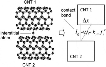
Considering that the kinematics of the problem resolves only the sliding of the CNTs, which causes shear relative motion of the bonded face-to-face segments, the shear stiffness of the contact bond is calibrated to represent the elasticity of the cross-link. In Fig. 1 we describe the calibration procedure. Assuming that at the vdW equilibrium interspacing l
0 = 3.35 Å the initial links are unstrained, the elastic behavior of the microscopic cross-link is incorporated into the shear force-displacement law of the contact bond. The critical elongation of the shear contact spring is
 $\Delta x = \sqrt {{{\left( {1 + {\varepsilon _{\rm{c}}}} \right)}^2}l_0^2 - l_0^2} = 3.75\,{\rm{{Å}}}$
. Based on the interatomic dependence of the classical potentials for carbon,
Reference Tersoff36
we infer that the cross-link can sustain a εc = 0.5 critical strain before it breaks. The shear stiffness of the DEM contact bond is found by equating at Δx the strain energy of the contact shear spring with the microscopic energy of two single covalent bonds 2E
b, where E
b = 3.6 eV.
Reference Tersoff36
It follows that
 $k_{\rm{s}} = {{4E_{\rm{b}} } \mathord /{\left {\vphantom {{4E_{\rm{b}} } {\left( {\Delta x} \right)}}} \right. \kern-\nulldelimiterspace} {\left( {\Delta x} \right)}}^2 = {{1.02\,{\rm{eV}}} \mathord /{\left {\vphantom {{1.02\,{\rm{eV}}} {{\rm{{Å}}}^2 }}} \right. \kern-\nulldelimiterspace} {{\rm{{Å}}}^2 }}$
. The strength of the DEM shear spring is
 $f_{\rm{c}} = k_{\rm{s}} \Delta x = {{3.82\;{\rm{eV}}} \mathord /{\left {\vphantom {{3.82\;{\rm{eV}}} {\rm{{Å}}}}} \right. \kern-\nulldelimiterspace} {\rm{{Å}}}}$
III. CNT BUNDLE ASSEMBLY AND MECHANICAL TEST SETUP
Our simulations considered close-packed bundle of CNTs with a hexagonal cross-section. The side of a hexagon is (N − 1)r
0, where N = 3 is the number of tubes along the side and r
0 = 17.1 Å is the center-to-center distance between the constituent CNTs. The number of CNTs that define the bundle cross-section is 1 + 3N(N − 1) while the cross-sectional area of the bundle is given by
 $S = 0.75\sqrt 3 \left[ {1 + 3N\left( {N - 1} \right)} \right]r_0^2$
. The simulated bundle has a length L of 271.2 nm comprising M = 4 individual CNTs. In a row of CNTs there is no spacing between the CNT caps and so distinct elements of each row of CNTs face the elements of neighboring rows. A number of cross-linking contact bonds presented are then distributed in a random manner over the volume of the bundle. The number of vdW contacts in the bundle is
 ${N_{{\rm{vdw}}}} = 800\left[ {3 + 9{{\left( {N - 1} \right)}^2}} \right] = 31,200$
. We denote by γ the ratio between the number of cross-linked elements and face-to-face vdW contacts.
In preparation for the simulation, the bundle is allowed to relax for 10,000 cycles, or 0.1 ns. We observe that the bundle contracts along the x-direction, leading to approximately 0.3% decrease in length and a decrease in elastic strain energy of 0.5 kJ/kg. Bundles may also develop lateral deformations, and store part of the elastic energy in bending. This behavior is due to the inherent asymmetry introduced by the randomly positioned cross-links. After the relaxation process is completed, two layers of distinct elements located at both ends of the bundle are designated as grip elements. The x degree of freedom of the grip elements are kept fixed, and the bundle is equilibrated for an additional 1000 cycles (0.01 ns), to ensure that the initial force acting on each grip is zero. A displacement-controlled loading is next achieved by accelerating the grip elements from 0 to the given velocity during 5000 cycles (0.05 ns). A stress–strain curve is recorded during the simulations. The tensile stress is defined as
 $\sigma _{xx} = {{F_x } \mathord{\left/ {\vphantom {{F_x } S}} \right. \kern-\nulldelimiterspace} S}$
, where F
x
is the x-component of the force acting on the grip. A nominal strain is defined as
 $\varepsilon _{xx} = {{2u_x^{\rm{g}} } \mathord{\left/ {\vphantom {{2u_x^{\rm{g}} } L}} \right. \kern-\nulldelimiterspace} L}$
, where
 $u_x^{\rm{g}}$
is the x-component of the grip displacement.
To examine the sliding of the CNTs during the tensile load, we have computed for each distinct element i its slip vector
 ${\vec \delta ^i}$
, defined as
 $${\vec \delta ^i} = {1 \over {{\lambda _i}}}\mathop\sum\limits_{j = 1}^{{\lambda _i}} {\left( {{{\vec X}^{\left( {ij} \right)}} - {{\vec x}^{\left( {ij} \right)}}} \right)} \quad {\rm{.}}$$
Here
 ${\vec x^{\left( {ij} \right)}}$
and
 ${\vec X^{\left( {ij} \right)}}$
are the vector differences between the coordinates of elements i and j in the current and initial states, respectively, and λ
i
is the number of nearest-neighbor elements for i in the initial reference configuration. We have also monitored the energy balance during the quasistatic tension tests, given by
 $${A_{{\rm{ext}}}}\left( \varepsilon \right) = \Delta {U_{{\rm{pot}}}}\left( \varepsilon \right) + \Delta Q\left( \varepsilon \right)\quad {\rm{.}}$$
Here
 ${A_{{\rm{ext}}}}\left( \Delta \right)$
is the work done by the external load. ΔU
pot is the change in the total potential energy of the bundle comprising ΔU
str the change in the strain energy of individual CNTs; ΔU
bonds, the elastic energy stored in the cross-links; and ΔU
vdw, the change in the vdW adhesion energy associated with the formation of new vdW surfaces; and ΔQ, the energy dissipated by local and viscous damping.
IV. RESULTS AND DISCUSSION
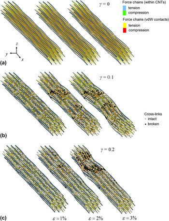
We first focus on understanding the mechanical response. The evolving force-chain network, shown in Fig. 2, governs the complex response of the CNT bundle to the applied tensile load. In all of the considered CNT bundles with three representative densities of cross-linking (with γ being 0, 0.1, and 0.2), the individual CNTs provide stable force chain portions for carrying the applied tensile load. Although the vdW contacts between CNTs, some of which are filled with cross-links, undergo massive breakages, they are still able to ensure load transfer between individual CNTs for the entire duration of the tensile tests. (Note that in Fig. 2 the breaking of the vdW bonds is not represented.) Additionally, in Figs. 2(b) and 2(c), it can be seen that more and more cross-links are breaking under the increasing applied strain, leading to the formation of nanoscale-localized fracture zones.
The elasticity and strength of a microscopic sp 3-sp link between two CNTs is represented in DEM via the shear strength and stiffness values of the contact bond between distinct elements located on the two CNTs.

CNT bundle at different strain levels, showing force chains as cylinders with the thickness dependent on the magnitude of normal force. Tension and compression within CNTs are in blue and green respectively. Load transfer through vdW forces is visualized with semitransparent cylinders, yellow in tension and red in compression. Also visible are the distributions of the interstitial atoms containing intact (white) and broken (black) cross-links. The tensile tests considered bundles with three cross-link densities: (a) γ = 0, (b) γ = 0.1, and (c) γ = 0.2.

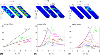
More insight emerges from Fig. 3, which displays the slip vector magnitude and energy components. On one hand, the CNT of the pristine bundle, Fig. 3(a) exhibits significant sliding even at the incipient stages of the deformation. The force chains passing through the CNTs carry little load, as it can be seen in the evolution of the strain energy component. The CNT sliding causes significant growth of the vdW and dissipation energy components. On the other hand, the presence of cross-links successfully inhibits the CNT sliding, Figs. 3(b) and 3(c), and the strain energy stored in the CNTs and cross-links dominates at the small strain levels. The work done by external forces practically equals the change in potential energy. Next, the γ = 0.1 (0.2) bundle under 2% (3%) applied strain starts to develop localized sliding in zones which coincide with the cross-link fracture areas identified in Fig. 2. Beyond these strain levels, the elastic energy stored in the bundle starts to exhibit a significant decrease, as the cross-link fracture zones increase in size. Post-peak deformation is associated with massive energy dissipation into the microscopic degrees of freedom. Using a CNT heat capacity value of 710 J/(kg K) we estimate an increase of the γ = 0.2 bundle temperature by 120 K.
Bundle axial cross-section showing the slip vector magnitude (above) and energy components (below) during tensile tests carried out with three cross-link densities: (a) γ = 0, (b) γ = 0.1, and (c) γ = 0.2.

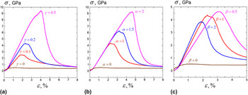
We now focus on the stress/strain relationship displayed by the CNT bundles. Each curve of Fig. 4 starts with a linear regime of loading (characterized by the Young's modulus E), followed by the yield, which occurs at the peak value of stress
 ${\sigma _{\rm{c}}}$
and corresponding strain
 ${\varepsilon _{\rm{c}}}$
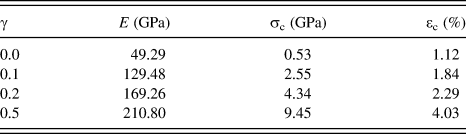
. The computational results presented in Fig. 4(a) show that the stress–strain curves are very sensitive to cross-linking. The values of E,
 ${\sigma _{\rm{c}}}$
, and
 ${\varepsilon _{\rm{c}}}$
, summarized in Table I, demonstrate a significant improvement in the mechanical properties with the cross-link density. In particular, we predict that cross-linking can improve the strength by an order of magnitude.
Stress–strain curves obtained by DEM simulation showing the dependence on the cross-links’ (a) density, (b) strength, and (c) stiffness. In (b) and (c) γ = 0.2.

Variations of the Young's modulus, critical strain, and stress with the cross-link density.

It is instructive to compare the values reported in Table I with the ones of an ideal bundle containing a similar hexagonal arrangement of CNTs each of length L. To perform this comparison, we rescaled the ideal CNT Young's modulus and tensile strengths by the ratio
 $\left( {{{S_{\rm{c}} } \mathord{\left/ {\vphantom {{S_{\rm{c}} } {S_{\rm{t}} }}} \right. \kern-\nulldelimiterspace} {S_{\rm{t}} }}} \right) = 2.6$
. Here, S
t and S
c are the cross-sectional area of the (10,10) CNT and the cross-sectional area occupied by the (10,10) CNT in a hexagonal bundle, respectively. We obtained an ideal Young's modulus of 385 GPa and strength of 56 GPa. As can be seen from Table I, the computed elastic moduli are approaching the ideal value. The smaller-than-ideal values for the bundles are caused by the compliance of the cross-links. However, the bundle peak stress and strains are still inferior to the ideal CNT yield values.
We have performed additional investigations to explore the impact of the strength and stiffness of the cross-link on the overall mechanical response. Figures 4(b) and 4(c) summarize our simulation results in which the cross-link DEM contact bond strength and stiffness values were multiplied by the dimensionless parameters α and β, respectively. From these simulations, we learn that a brittle response is favored by populating the CNT bundle with strong and stiff bonds. A ductile behavior can instead be achieved by introducing weak and compliant bonds. Stiffer bonds give rise to higher Young's moduli, as can be seen from the slopes of the initial linear variations shown in Fig. 4(c). To achieve large
 ${\sigma _{\rm{c}}}$
and
 ${\varepsilon _{\rm{c}}}$
values, a combination of strong and compliant cross-links is required. The latter requirement can be explained with the fact that compliant cross-links resolve significant relative slip of CNTs within the bundle, which leads to the formation of a new vdW surface and participation of vdW surface tension forces in the response.
Our DEM simulations are consistent with the full molecular dynamic simulations considering the same type of cross-linking in crystalline bundles made up of (5,5) CNTs.
Reference Cornwell and Welch22
These bundles with dense cross-links demonstrated Young's moduli on the order of 50 GPa and a fracture strain of 8%. To compare the strength, we have to first account for the difference in cross-sectional areas between (10,10) and (5,5) CNT bundles. On this basis, we extrapolate the MD value of the strength for (10,10) CNTs to be ∼18 GPa. These results are consistent with our DEM tests and can be captured with cross-links of comparable density and double strength
 $\left( {\alpha = 2} \right)$
. The factor of two in strength obtained in MD can be explained by the fact that interstitial atoms formed more than one single covalent bond with atoms on the CNT surfaces.
V. CONCLUSION
We developed a successful DEM representation for CNTs, by mapping the microscopic mechanics onto cylindrical distinct elements forming parallel contact bonds and vdW bonds with viscous damping. The DEM methodology was used to investigate the mechanics of a variety of CNT assemblies, including CNT films, rings, rackets, and bundles. Reference Ostanin, Ballarini, Potyondy and Dumitrică27,Reference Ostanin, Ballarini and Dumitricǎ33,Reference Wang, Semler, Ostanin, Hobbie and Dumitrică35,Reference Wang, Gaidau, Ostanin and Dumitrică37 Here, we enriched this framework by extending the interactions between the distinct elements to include covalent sp 3-sp links between CNTs. Our simulations provide a detailed mesoscale picture of the complex mechanical response of the CNT bundles with various cross-link densities, and capture the transformation of the bundle from a soft into a strong material. The DEM simulations presented here show good agreement with MD simulations and experiment Reference Filleter, Bernal, Li and Espinosa18 in all the important aspects and offer possible strategies for the further engineering of the stress–strain curve.
We emphasize that with the exception of viscous damping (shown to play a less important role – see the supplementary material), all other parameters of our model were obtained from microscopic data. We used DEM in a multiscale manner, to formulate “hands-off” predictions based on microscopic data. Neither complex global constitutive models nor assumptions about the location and type of yield are imposed a priori to simulate the mechanical response. By informing the contact models employed here with new data, our DEM approach can be readily used to investigate the impact on the mechanical response of other important cross-links. Reference O’Brien, McCarthy and Curtin16 Another effect that deserves further exploration is the influence of a cross-link distribution on the strength of the bundle. Reference O’Brien, McCarthy and Curtin20 Indeed, in practice the uniform distribution considered here is relevant for thin bundles only. For thicker bundles, the presence of cross-links is limited to the regions around the surface of the bundle. It was observed that increasing the dosage of irradiation improves the penetration and thus yields cross-links toward the middle of the bundle. However, the procedure also produces detrimental effects on the CNT structure, such as vacancy-related defects. Reference Osváth, Vértesy, Tapasztó, Wéber, Horváth, Gyulai and Biró38 The mechanical weakening of the individual CNT due to irradiation could also be captured by the parameterization of the DEM parallel contact bonds.
Supplementary Material
To view the supplementary material for this article, please visit http://dx.doi.org/jmr.2014.279.
ACKNOWLEDGMENTS
We thank the Itasca Consulting Group for the PFC3D software support. I.O. and T.D. acknowledge the support of the NSF through CMMI 1332228.