

I. INTRODUCTION
Plutonium is one of the products from the nuclear reactions in the nuclear fuel. It has been separated from spent fuel not only as a potential energy source, but in the past also to produce nuclear weapons, a substantial fraction of which is nowadays being dismantled. Thus, currently about 264 metric tons of separated civilian plutonium are stocked and around 224 metric tons of military plutonium. 1 The reprocessing of this element, producing PuO2, and using it, along with depleted uranium dioxide, to obtain mixed-oxide fuel (MOX) Reference Mors2 is a possible way to manage the stocks, but the secure storage meanwhile is mandatory, and possibly this storage could last for decades or even centuries. Thus, it is necessary to study the aging process of these compounds to ensure a safe storage and to anticipate their retrieval. Reference Ferry, Poinssot, Cappelaere, Desgranges, Jegou, Miserque, Piron, Roudil and Gras3 The overall effects of damage on the integrity of the materials and the behavior of helium that, if released, could build some pressure in storage containers, needs to be characterized and understood.
Not only separated plutonium but also significant amounts of spent uranium dioxide nuclear fuel are accumulating worldwide from decades of commercial nuclear power production. Around 300,000 tons of spent fuel from civil power plants are currently stored in the world Reference Feiveson, Mian, Ramana and von Hippel4 and this amount steadily grows. While nuclear fuel in reactor undergoes significant restructuring due to the radiation effects from fission and to operating high temperatures, the radiation and temperature environment for spent fuel out of reactor is substantially different. After decay of the short-lived fission products the spent fuel activity will be dominated by alpha-decays from the minor actinides and mainly from plutonium for the longer times. Reference Ferry, Piron and Ambard5 The self-radiation damage and helium accumulation at near ambient conditions will dominate for millions of years. The spent nuclear fuel available and characterized today is not representative of the structure and state of aged spent fuel after hundreds or thousands of years of storage because it has not yet experienced a significantly long accumulation of microstructural defects and of He due to α-decay. Reference Rondinella, Matzke, Cobos and Wiss6
Recently, the Fukushima event has raised public awareness, also regarding spent fuel storage in pools. While such spent fuel is intended to be reprocessed or disposed in geologic repositories, out-of-reactor radiation damage from alpha decay can be detrimental to its structural stability and hence be of concern during its storage in pools or during its transport, so even at timescales below disposal times. To predict the long-term behavior of such material only accelerated aging or possibly natural analogs can be used. To assess the impact of alpha-damage and helium behavior in aged spent fuel, UO2 samples with different content of 238PuO2 have been prepared and studied for different levels of damage simulating different ages of spent fuel. The extreme case was the study of (initially) pure 238PuO2 retrieved from radioisotope thermoelectric generator (RTG Reference O'Brien, Ambrosi, Bannister, Howe and Atkinson7,Reference El-Genk and Tournier8 ).
Another area of investigation of aging of actinide compounds is related to the space conquest in which spacecrafts are to be sent to the outer space. To keep instruments running over several decades, with not enough sunlight when traveling (or landing unforeseen on a shaded area of a comet like the probe Philae did on November 2014 (Ref. Reference Hand9)), they will need long-time batteries. 238Pu has been the isotope of choice for five decades. Reference El-Genk and Tournier8 The main problem in today's use is the availability and price of this radioisotope. In addition, having a half-life of 87.74 years, after several years of operation, the power of the plutonium-based batteries diminishes. Hence, the electronics need to be far more complicated than usual. Reference Prelas, weaver, Watermann, Lukosi, Schott and Wisniewski10
As an alternative, it has been proposed to use 241Am. Reference Baker, Bell, Brown, Carrigan, Carrott, Gregson, Clough, Maber, Mason, Rhodes, Rice, Sarsfield, Stephenson, Taylor, Tinsley, Woodhead, Wiss and Ouwehand11 To its credit, the resources of this actinide at the moment are large, and more can be produced. Reference Baker, Bell, Brown, Carrigan, Carrott, Gregson, Clough, Maber, Mason, Rhodes, Rice, Sarsfield, Stephenson, Taylor, Tinsley, Woodhead, Wiss and Ouwehand11 One possibility of obtaining 241Am is by reprocessing spent fuel, which contains about 12% 241Pu, from the total Pu inventory at discharge, that decays into 241Am with a half-life of 14 years. However, this process is slow: Half of the original amount of 241Pu decays to 241Am in about 14 years, and the 241Am amount reaches a maximum after 70 years.
As 241Am has a significantly longer half-life than 238Pu (∼432 years versus ∼87 years), the power of the batteries would be much more stable, Reference O'Brien, Ambrosi, Bannister, Howe and Atkinson7 simplifying the design of the electronics. However, the peak-power would be lower (114.7 mW g−1 versus 390 mW g−1), and the weight needed much higher than usual batteries, but the lower price on the precursor material makes it an interesting option. This would need, however, to be balanced by the cost of extra weight shipped to space.
To be able to design suitable space batteries, more studies on 241AmO2 need to be made. To this matter, a comparison between its microstructure evolution to the one of 238PuO2 can be of use.
Last but not least, actinides as contributors to the high toxicity of spent fuel, and americium in particular for the medium time range, could be transmuted in the so-called minor actinide bearing blankets (MABB) in fast neutron reactors or accelerated driven systems. Reference Prieur, Jankowiak, Roudil, Dubois, Leorier, Herlet, Dehaudt, Laval and Blanchart12 The properties of such materials need to be thoroughly investigated and good knowledge of the precursor materials, hence AmO2, understood. Because of the fast aging of the highly active AmO2 it is also of importance to determine the radiation damage effects on the timescale concerned with the storage and fabrication of MABB, for example in U1−x Am x O±δ compounds. Reference Lebreton, Martin, Horlait, Bès, Scheinost, Rossberg, Delahaye and VBlanchart13
The chemical and physical consequences of self-radiation in actinide compounds are rather complex. It is often difficult to deduce the true physicochemical properties of substances when superimposed by radioactive decays and their effects. Reference Staicu, Wiss, Rondinella, Hiernaut, Konings and Ronchi14
Alpha-decay in oxides typically results in the formation of points defects, mainly from the recoil nucleus and to the formation of a helium atom when the alpha-particle comes to rest. The point defects can also precipitate into larger extended defects (e.g., loops) and the helium atoms into bubbles. To observe these types of microstructural features one of the ideal probes is a transmission electron microscope (TEM) that enables with modern instruments to easily visualize objects in the nanometer (even lower) scale. In addition to conventional TEM imaging, elemental (energy dispersive x-ray spectroscopy) and spectroscopic analyses (electron energy-loss spectroscopy, EELS) proved to be of additional help to characterize changes complementary to the microstructure due to alpha-decay damage.
An effect of self-radiation and radioactive decay is the change in impurity content of the compound, due to the ingrowing daughter(s). This change influences the electrical resistivity as well as the lattice parameters (see e.g., Ref. Reference Matzke15). Other effects, which can be regarded as primary effects of the decay process, are the ionization, electronic excitation, and atomic displacements. The relative magnitude of each of these phenomena depends on the type and energy of the particle and on the substances. Reference Wiss, Konings, Vajda and Costantini16,Reference Wiss and Konings17
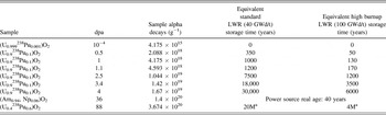
Table I lists the samples that have been used for this study showing that the decay dose covers six orders of magnitude. Defect accumulation is predicted to result in swelling of the atomic structure, whereas the accumulation of helium will produce bubbles that result in much larger gaseous-induced swelling that could increase the stresses in the constrained spent fuel leading to its disintegration.
List of the samples investigated and discussed in this study. In addition, the equivalent time for damage build-up for spent low and high burn-up fuel hence for different dpa values, as those seen in Fig. 11, are also indicated.

a The equivalent storage time is not relevant for conventional LWR UO2-fuel where the only residual activity is from the uranium left. It could however be representative of a MOX fuel with high burnup.
The composition is the one at the time of the investigation.
To our knowledge, the effect of 241Am self-irradiation has been previously studied for AmO2; however, the majority of the work conducted has been limited to the effect of self-irradiation on the lattice parameter Reference Hurtgen and Fuger18,Reference Nellis19 and thermal conductivity. Reference Schmidt, Richter, Matzke, Van Geel and Tong20 Much more work was performed on 238PuO2 since this compound has already been used in RTGs including batteries for space probes and even in pacemakers. Reference Boucher and Quere21,Reference Alais, Berger, Boucher, Gasper and Laurens22
The use of 238Pu-doped UO2 as a surrogate to spent fuel has been reported elsewhere Reference Rondinella, Cobos, Matzke, Wiss, Carbol and Solatie23–Reference Wiss, Hiernaut, Roudil, Colle, Maugeri, Talip, Janssen, Rondinella, Konings, Matzke and Weber25 but some original results showing the evolution of the microstructure of the (U x , Pu1−x )O2 are presented in this paper, the 238PuO2 being the starting material of the sample self-irradiated at the highest dose. It should be noted at this point that the decay product of 238Pu being 234U, the chemical composition does not evolve further than the fluorite type compound (U x , Pu1−x )O2. For 241Am the decay product being 237Np with a half-life of 2.14 × 10⁶ years yields the same result of no further chemical evolution.
In this paper we present studies on 241AmO2, 238PuO2, and 238Pu-doped UO2, showing the power of the transmission electron microscopy to help in the understanding of the aging processes.
II. EXPERIMENTAL
The 238PuO2 sample was retrieved from an old 242Cm RTG after full decay of curium. At time of the first TEM investigation the sample was 37 years and at the time of the second the sample was 41 years old, respectively. It was kept all the time in N2 atmosphere (traces of oxygen cannot be excluded) and when studied, it had an activity of about 5 × 10¹¹ Bq·g−1. Pre-annealing and post-annealing analyses were done to view the effect of the annealing process on the alpha-damage due to the self-radiation. The thermal treatment was done in an active, Knudsen cell, Reference Colle, Maugeri, Thiriet, Talip, Capone, Hiernaut, Konings and Wiss26 up to 2800 K. Another set of UO2 samples containing different amounts of 238Pu is also presented. Given the short half-life of 238Pu, all the samples investigated referred to as 238PuO2 in the discussion are indeed only referring to their original composition at the time of synthesis. The 238Pu-doped samples listed in Table I have all been produced via a sol–gel method Reference Fernandez, Richter and Somers27 enabling a homogeneous dispersion of the alpha-dopant in the material.
Two AmO2 samples were retrieved from the JRC-ITU archives after several years of storage. Reference Prieur, Vigier, Wiss, Janssen, Rothe, Cambriani and Somers28 No particular precautions regarding the storage were taken – samples were stored in air and at room temperature.
Table I lists the damage dose of the samples studied. The displacements per atom (dpa) were calculated using Stopping and Range of Ions in Matter (SRIM) Reference Ziegler, Biersack and Littmark29 and assuming a displacement energy of 40 eV for the cations (U, Np, Pu, Am) and of 20 eV for oxygen, respectively. From the SRIM calculations 1300 displaced atoms for a typical recoil nucleus of 100 keV and ∼200 displaced atoms for a typical 5.5 MeV alpha-particle were obtained respectively. These values vary little between the actinides and the materials considered in this study and constitute therefore indicative values. It is not intended to discuss the validity and the accuracy of the calculation but rather to have a normalized value for the damage. Some equivalent (in terms of damage dose) standard (45 GWd/t) spent fuel ages are indicated for comparison.
The samples studied by TEM were prepared by crushing grains of a few milligrams amount in methanol in an agate mortar. After decanting, some drops of this suspension were dripped over a 400 mesh copper grid coated with carbon. Due to the high activity of the samples, the preparation was performed inside glove boxes.
The investigations have been performed using a FEI Tecnai G2 TEM (FEI Company, Hillsboro, OR), equipped with a GATAN Tridiem GIF camera, an energy dispersive x-ray analysis (EDXA) system, a tomography suite and a high-angle annular dark field (HAADF) detector for the scanning transmission electron microscopy (STEM) imaging. TEM has been modified during fabrication for the examination of highly active or irradiated nuclear materials thanks to a flange that has been inserted in the octagon hosting the objective lenses, and a glove box mounted on this flange around the compustage. Reference Wiss, Thiele, Janssen, Papaioannou, Rondinella and Konings30 Thus, the sample can be moved from the glove box where it was prepared to the microscope making use of a La Calhène DPTE® system.
The scanning electron microscope (SEM) used in this study is a Philips XL40 (Philips, Amsterdam, Netherlands) at which the column, chamber and high voltage power supply has been mounted inside a glove-box allowing the confinement mandatory for the handling of radioactive material.
III. RESULTS AND DISCUSSION
A. AmO2
The intense α-decay rate of 241Am causes significant radiation damage. Most of this damage is caused by the daughter, the 237Np ion, which receives a recoil energy of 91 keV. About 1200–1300 lattice atoms are displaced in the dense collision cascade along its range of about 20 nm as determined by SRIM. Reference Ziegler, Biersack and Littmark29 In contrast, the emitted α-particle of 5.5 MeV has a long range of about 12 µm and creates much fewer displaced atoms, ∼200 only. The total number of atomic defects per α-decay is thus 1500. This corresponds to a damage level of 1 dpa in AmO2 within 1 wk of storage. Molecular dynamic calculations Reference Van Brutzel and Rarivomanantsoa31 tend to show that the total number of displaced atoms in an alpha-decay cascade has been previously largely underestimated. This will/would affect the calculated number of dpa. It is however, not the goal of this paper to review this aspect and the SRIM calculated values are used for all the dpa calculation.
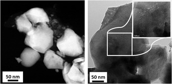
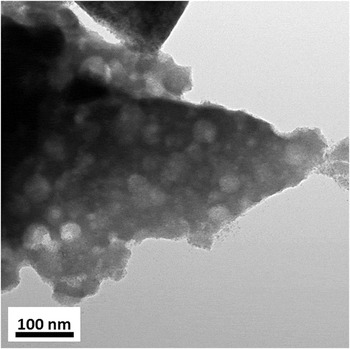
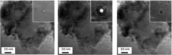
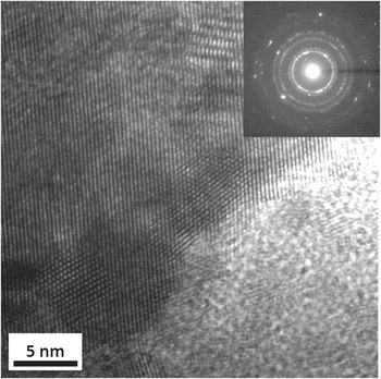
Figure 1 shows a scanning transmission electron microscope (STEM) micrograph and a bright-field TEM image of a sample of AmO2 having cumulated a dose of 1.4 × 10²⁰ α·g−1 after 36 years of storage. Helium bubbles of different sizes could be evidenced. The larger bubbles observed, as shown in the TEM image of Fig. 2, have size of up to 30 nm. There is also a population of very small intragranular nanometer sized bubbles, which are shown in the over-focused, focused, under-focused TEM images in Fig. 3. In this area, the bubbles are homogeneously distributed and their concentration amounts around 5 × 10²² m−3. The TEM image of Fig. 1 also shows that smaller bubbles are found aligned along the grain boundaries. In this case the grains, as shown in Fig. 1, have sizes of about 100 nm. High-resolution TEM (HRTEM) images, as shown in Fig. 4, revealed that the fine microstructure varied in the sample. In the investigated area imaged in Fig. 4, grains having sizes of about 5 nm were observed. In these grains, neither bubbles were observed nor defects (extended). The microstructure of this material is hence not homogeneous. The very large grains show the larger bubbles whereas the smallest (around 5 nm) bubbles are free of defect/bubbles. Intermediate grain sizes of around 50–100 nm showed bubbles of sizes between 2 and 5 nm. The crystallite sizes as determined by the Scherrer equation Reference Scherrer32 in Ref. Reference Prieur, Vigier, Wiss, Janssen, Rothe, Cambriani and Somers28 is in accordance with observation. Due to defect formation the lattice expands, reaching saturation at damage levels of a few dpa. For AmO2 saturation is reached for a lattice parameter change of ∼2.5 × 10⁻³ within about 100 days, with most change occurring in 1–2 wks. This is the reason, together with different impurity contents (mainly Pu and Np), that different lattice parameters have been reported previously. Reference Casalta, Matzke and Prunier33
STEM image of aged AmO2 showing the presence of bubbles (gray spots) on the left and bright-field TEM image showing a high concentration of helium bubbles on the right. The smaller helium bubbles in the right micrograph are precipitating at grain boundaries, as shown in the inset.

Bright-field TEM image of AmO2 showing a high concentration of larger bubbles.

Series of focused, under-focused, over-focused bright-field TEM image showing the presence of nanometer sized helium bubbles. The insets are showing a magnified bubble from the images.

HRTEM image of the damaged AmO2 showing the intimate microstructure constituted of tiny grains of about 5 nm. The diffraction in the inset confirms the polycrystalline nature of the selected area.

An exponential law is often used Reference Hurtgen and Fuger18,Reference Nellis19,Reference Chikalla and Eyring34 to describe the unit cell evolution with the cumulative decay dose:
 $${{a - {a_0}} \over {{a_0}}} = A \times \left( {1 - {e^{ - B\, \times \,\alpha }}} \right)\quad ,$$
where a is the lattice parameter measured at time t, a 0 is the initial value of the lattice parameter, A is the value at saturation, and B is a recombination volume. Reference Weber35 A and B are constants to be determined from the experimental data and α is the cumulative decay dose in the sample. A is the lattice parameter increase at saturation and B is related to the mean damage volume per alpha-decay event. This asymptotic behavior implies that the lattice parameter will not change in time, once the saturation value is reached. Reference Wiss, Hiernaut, Roudil, Colle, Maugeri, Talip, Janssen, Rondinella, Konings, Matzke and Weber25 The lattice parameter for fresh AmO2 ranges between 5.372 and 5.377 Å. Reference Hurtgen and Fuger18,Reference Chikalla and Eyring34 After 100 days, an increase of 0.2–0.3% is observed, the unit cell reaching a value in the range of 5.385 and 5.392 Å. Reference Prieur, Vigier, Wiss, Janssen, Rothe, Cambriani and Somers28 In Table II the values of the A and B parameters as measured previously are reported as well as the A value of the AmO2 sample studied here. It could be shown that there is a slight increase of the saturation value of the lattice parameter increase (A) possibly attributed to some more pronounced defect segregation due to the presence of bubbles acting as sinks for the newly produced vacancies.
A and B values of Eq. (1) for different AmO2 samples.

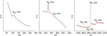
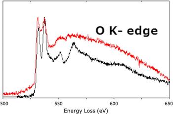
Electron energy loss spectra (EELS) of the AmO2 sample for the Am M4, M5, N4, N5, and O4,5 are shown in Fig. 5. In the high energy loss range the contribution from the 6% of radiogenic neptunium is very clear and has been quantified to confirm the age of the material. Figure 6 shows the EELS spectra recorded on the O-K edge before (red) and after annealing (black). The loss of symmetry around the oxygen atoms is evidenced in the fine near edge structure by the shape of the peaks that recover after annealing. The EELS spectra can be compared to XANES O-K edge experiment as in both techniques oxygen 2p empty states are probed. As AmO2 and UO2 share the same fluorine structure, the latter would correspond to what would be expected for a non-damaged AmO2 sample. The spectra collected for the annealed sample (in black) is very similar to XANES spectra collected for a stoichiometric UO2 Reference Martin, Ripert, Carlot, Parent and Laffon36 : two intense sharp peaks at ∼530 and ∼538 eV corresponding to O2p-5f and O2p-6d hybridization bands, Reference Tobin and Yu37 and different resonances up to 570 eV due to multiscattering (MS) contributions of successive coordination shells around oxygen atoms within the fluorine structure. Reference Wu, Jollet, Gota, Thromat, Gautier-Soyer and Petit38 On this basis, the absence of these MS contributions in the damaged sample (red) clearly shows the lack of short range order around oxygen atoms. But, even less intense the two peaks at ∼530 and ∼538 eV are still clearly observed which is consistent with the FCC structure observed (see Fig. 4).
EELS spectra of a 36 dpa AmO2 sample covering all measurable energy range for the Am edges.

Graph showing the O-K peak for the annealed sample of AmO2 (the lower curve, black in colored version) and the disappearance of the fine structure of this peak on the damaged sample (upper curve, red in colored version).

Earlier work showed that from the rate of change in the thermal conductivity λ, a defect saturation concentration could be estimated, above which the thermal conductivity of the material measured under certain conditions is no longer affected. In the case of AmO2 this was achieved after 3 days. Reference Schmidt, Richter, Matzke, Van Geel and Tong20
Damage-induced changes in the thermal conductivity can recover upon annealing. There is a recovery stage at about 200 °C, attributed to annealing of oxygen defects, and complete recovery is achieved at about 800 °C, i.e., when metal atom defects anneal. Reference Casalta, Matzke and Prunier33
As a first preliminary conclusion it appears that the microstructure of AmO2 is not severely affected even at high damage levels. The lattice parameter evolution shows saturation at a value of 0.3% and only the formation of bubbles at very large cumulated dose should be accounted for when determining the swelling of such compounds. Such parameters are of importance when designing batteries envelopes for example.
B. (U1−x , Pu x )O2
The emission of a recoil nucleus with approximately 85 keV and an alpha particle with around 5 MeV are the sources of the alpha-decay damage from 238Pu. Together, those two effects produce about 1600 displacements in PuO2 and the result is the formation of Frenkel pair defects, along with one helium atom per decay. Table I shows the calculated alpha damage accumulated as a function of storage time for several samples composed of uranium and plutonium oxides. Making use of TEM, it was possible to view experimentally the accumulation of the damage on the (U x , 238Pu1−x )O2 samples.
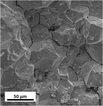
The defects which accumulate in the lattice may end with three different processes: annihilate at microstructural features such as dislocations or voids, precipitate as defects, such as gas bubbles, clusters, or dislocations, Reference Staicu, Wiss, Rondinella, Hiernaut, Konings and Ronchi14 or may recombine and disappear, within the time frame of the collision cascade. The SEM secondary electron image in Fig. 7 shows the detrimental effect of severe alpha-damage on the microstructure of an old PuO2 sample. Opening of grain boundaries occurred, which can be attributed to migration of helium and probably trapping of vacancies.
Secondary electron micrograph of the aged 238PuO2 sample showing the opening of grain boundaries.

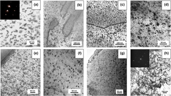
Figure 8 shows a series of bright-field TEM micrographs that highlight the accumulation of defects in the sample as a function of dpa. It shows that dislocation loops appear at very low dpa values and that their concentration increases with the alpha-dose. However, no significant increase in size is observed and their concentration appears also to saturate (within the limits of observation). At a much higher damage dose of 88 dpa the microstructure evolves from dislocation loops to dislocation tangles. This phenomenon of the evolution of dislocation loops to dislocation tangles has been recently observed in Kr-irradiated UO2. Reference He, Gupta, Yablinsky, Gan, Kirk, Bai, Pakarinen and Allen39 The evolution of point defects toward these extended defects contribute to minimize the overall strain and lattice swelling in the samples. The saturation of the lattice parameter observed in (U x , Pu1−x )O2 is also explained by the steady state reached by annihilation of point defects on the extended defects. Reference Wiss, Hiernaut, Roudil, Colle, Maugeri, Talip, Janssen, Rondinella, Konings, Matzke and Weber25
Defects in plutonium compound as a function of α-damage: (a) 10−4 dpa, (b) 0.5 dpa, (c) 1 dpa, (d) 1.1 dpa, (e) 2.5 dpa, (f) 3.4 dpa, (g) 4 dpa, and (h) 88 dpa.

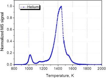
The 238PuO2 sample has been annealed in a Knudsen cell and the helium desorption measured. Figure 9 shows the start of the helium release from the 238PuO2 sample at 1000 K. The release occurs in three distinct steps: in the range 950–1100 K the release is due to the helium adsorbed on the surface. At 1150 K release a small contribution from the helium trapped in pores between the agglomerated grains can be observed. The 1150–1600 K main release peak is due to release of the helium located in the grains, probably precipitated in tiny bubbles, which diffuses, via grain boundaries, to the surface.
Annealing of helium in the 238PuO2 sample as a function of temperature.

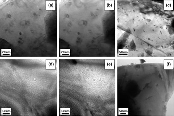
To view the effect of the annealing on the number of defects and on the helium desorption, micrographs of a 0.1 wt% 238Pu-doped UO2 sample before and after annealing were taken as shown in Fig. 10, in the first set of images (a–c) for the sample annealed at 1400 K several dislocation loops can be seen, along with a lot of bubbles – the bubbles can be distinguished in under and over focused images, as they appear as white spots in the former and black spots in the latter. On the other hand, the second set of images (d–f) shows the sample after annealing at 1800 K; the number of bubbles decreased whereas their size increased, and no dislocation loops can be observed anymore. The diffusion coefficient of helium and bubble diffusion coefficient could be extracted from the modeling of the corresponding helium release profiles as described in Ref. Reference Talip, Wiss, Di Marcello, Janssen, Colle, Van Uffelen, Raison and Konings40.
Micrographs of the 0.1 wt% 238Pu-doped UO2 sample: (a–c) bubbles and dislocation loops after annealing at 1400 K; (d–f) bubbles after annealing at 1800 K.

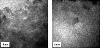
The microstructure of the 238PuO2 sample has also been investigated before and after annealing as shown in the two bright-field TEM micrographs of Fig. 11 for the as stored (left) and annealed (right) sample, respectively. In the case of this sample, helium bubbles were observed already in the as-stored sample but they are not visible on the left image due to their nanometric size; after annealing they follow the same behavior as observed in Fig. 10, i.e., the bubbles coalesce into much less but larger bubbles having size of several nanometers, as the bubble seen on the right image.
HRTEM of the 238PuO2 sample (88 dpa), before annealing (left) and after annealing at 1500 K taken on different grains (as the annealing was done outside of the microscope, in a Knudsen cell). The left bright-field image shows the small 5 nm sized grains while the right image clearly evidences a bubble.

The characterization by TEM of alpha-damaged samples containing 238Pu to accelerate their aging was efficient to contribute to the prediction of the microstructure of equivalent old irradiated spent fuel.
IV. CONCLUSION
To predict the behavior of plutonium dioxide and to a certain extent of spent fuel during long-term storage, radiation-induced defects have been studied. The investigation of alpha-damage by means of TEM showed the formation of dislocation loops and helium bubbles. The amount of the respective features can be quantified as a function of the alpha/damage dose. Reference Talip, Wiss, Di Marcello, Janssen, Colle, Van Uffelen, Raison and Konings40,Reference Jonnet, Van Uffelen, Wiss, Staicu, Rémy and Rest41 Annealing studies demonstrated that neither, diffusion of helium, nor substantial recovery of defects will occur at the temperature expected for storage. Given the temperature needed to anneal alpha-defects and to initiate helium thermal diffusion it can be expected that plutonium dioxide will be able to accommodate in its damaged structure a large part of the radiogenic helium that will be created but, while remaining crystalline, this material will experience a high stress level, and it is expected that its overall microstructure will be perturbed by formation of these nanosized gas bubbles and extended alpha-damage defects (dislocation loops).
Despite the high α-irradiation dose in AmO2, the sample remains crystalline. The microstructure examination of this material revealed that only few extended defects are formed. Given the very high alpha-dose, the material has experienced rather good resistance to radiation damage build-up. The formation of two populations of (He) bubbles is also surprising. On one side, very large bubbles are observed with sizes of up to 30 nm. On the other side, there is a background of sub-nanometric bubbles that can be observed in other grains of the material. This has been attributed to different stages in the evolution of the damaged pattern, i.e., the precipitation of nanometric He-bubbles and loops to more defect free but nanocrystalline areas. For instance, the formation of larger bubbles can be associated to the precipitation of vacancies. The microstructure of the AmO2 sample appears to be less affected by the alpha-damage than the (U x , Pu1−x )O2. The compound, AmO2−δ, with 1.98 < δ < 2.00 is stable below 1100 K Reference Thiriet and Konings42 and the formation of oxygen vacancies explains the better defect recovery and helium accommodation. More research will be performed to determine the impact on the radiation stability of the (U x , Pu1−x )O2 compounds when deviating from stoichiometry.
The TEM and its related characterization techniques (HRTEM, diffraction, EELS) have shown its suitability for the study of radiation damage in ceramic actinide samples. It is not sufficient to characterize the radiation damage produced at an atomic scale like the point defects that impact directly the thermal transport for example. However it showed to be extremely useful to characterize microstructural features starting at a nanometric size and to support other measurements like lattice parameter changes for example.