1. Introduction
The global navigation satellite system (GNSS) and inertial navigation system (INS) are integrated with a Kalman filter to obtain the optimal state estimation (Cui et al., Reference Cui, Wei, Chen, Li and Li2019; Liu et al., Reference Liu, Chen and Wang2023), which combines the advantages of both technologies to offer an accurate and complete navigation solution, and thus has been widely used for motion compensation in remote sensing applications.
The navigation solution errors in the GNSS/INS integrated system mainly arise from initialisation errors, inertial sensor errors and processing approximations, which include gravity disturbances, lever-arm errors and timing synchronisation errors. The initialisation errors are generally calibrated by GNSS alignment, which uses position and velocity derived from GNSS as Kalman filter observations (Zhong et al., Reference Zhong, Guo and Zhou2018; Zhong et al., Reference Zhong, Chen, Zhou and Wang2023). Additionally, the inertial sensor errors, including biases, scale factor errors, cross-coupling errors, higher-order errors, random noise and more, make up 70%–80% of error sources (Lo and Gao, Reference Lo and Gao2021; Zhong et al., Reference Zhong, Chen, Zhang, Sha and Li2024), which are normally compensated by building an exact error model. Knudsen (Reference Knudsen1985) proposed a 93-state INS error model for the Litton inertial navigation unit, which contained position errors, velocity errors, attitude errors, vertical channel errors, gyro and accelerometer bias, gyro and accelerometer scale factor errors, gyro and accelerometer misalignments, gyro and accelerometer initial thermal transients, etc. Although the INS error model with 93 states is the fairly accurate characterisation in theory, the high degree of dimensionality would result in the huge calculation burden. Lewantowicz and Keen (Reference Lewantowicz and Keen1991) constructed a 39-state INS error model, which eliminated a number of states from the 93-state Litton model state space and does not produce significant errors. Additionally, the research results have demonstrated that the 39-state is a sufficient substitute for the 93-state model without a significant loss of accuracy.
In commercial integrated navigation software, a simple INS error model is often adopted for low-dynamics application, which only consists of 15 states including position/velocity/attitude errors and gyro/accelerometer constant bias. The 15-state INS error model provides a rough approximation to the accelerometer and gyro behaviours, which is accounted for by modelling each bias state as the sum of a constant state and white system noise. The simplification of error model has led to increase the processing efficiency of integrated navigation, but can involve a certain accuracy loss of navigation solution. In the high-dynamic environment, such as ballistic missile, rocket and indexed INS applications, the size effect and higher-order errors may also occur and behave like a bias that varies with the amplitude of the vibration. Gao et al. (Reference Gao, Li, Song and Liu2018) and Hu and Wang (Reference Hu and Wang2023) respectively built their INS error models considering the influence of accelerometers size effect and quadratic errors, which were estimated as Kalman filter states through optimal estimation. In aerial remote sensing application, the INS error propagation is affected by the aircraft manoeuvres. Sun et al. (Reference Sun, Yuan and Fu2010) developed a 36-state INS error model for the aerial remote sensing application with random constants to characterise the accelerometer and gyro scale factor errors, the effect of which on navigation error growth depended on the aircraft manoeuvres. In the 36-state INS error model, the accelerometer and gyro cross-coupling errors are supposed to be completely compensated after calibration. However, the calibration results generally have some deviations compared with the truth, which would have direct influence on the navigation accuracy. Chen and Fang (Reference Chen and Fang2013) established a 45-state INS error model for airborne InSAR application, which was built on the feature of the 15-state INS error model by augmenting the system states with scale factor errors, cross-coupling errors, random walks errors and first-order Markov process errors. The simulation results show that the 45-state INS error model has higher navigation accuracy compared with the traditional 15-state INS error model. However, in the actual environment, the dynamic component of the accelerometer and gyro biases is typically approximately 10% of the static component, so accelerometer and gyro biases can be simplified by modelling each bias as the sum of a constant and a Markov state, and the modelled errors adequately overbound their real counterparts.
However, the system error model of GNSS/INS is conditioned on the estimated Kalman filter states, which depends not only on the gyro and accelerometer measurement errors, but also upon some approximate processing errors. Skog and Handel (Reference Skog and Handel2011), He et al. (Reference He, Li, Zhang and Zhang2022) and Li et al. (Reference Li, Li, Zhou, Wang and Chen2024) adopted the software-based time synchronisation method to remove the timing error between GNSS and INS, where the time synchronisation error was included as a Kalman filter state to be estimated and compensated. Fang et al. (Reference Fang, Chen and Yao2014), Wang et al. (Reference Wang, Yan, Fei and Zheng2020) and Luo et al. (Reference Luo, Yu, Wu, Cao and Huang2024) constructed their respective statistical models of the gravity disturbance, which are embedded into the system error model for the gravity disturbance estimation and removal online by a Kalman filter. Xiong et al. (Reference Xiong, Peng, Wang, Wang and Liu2015), Chen et al. (Reference Chen, Zhang, Han and Li2020) and Zhang et al. (Reference Zhang, Hu and Niu2020) extended lever-arm errors between GNSS and INS as Kalman filter states, which were estimated and compensated in real time by adopting the closed-loop correction architecture.
Especially for the high-precision GNSS/INS integrated system, various kinds of error factors should be considered seriously. In this paper, we establish a high-dimensional error model of the loosely coupled GNSS/INS integration, which is composed of 42 error states including position/velocity/attitude errors, gyro/accelerometer static biases, gyro/accelerometer dynamic biases, gyro/accelerometer scale factor errors, gyro/accelerometer cross-coupling errors, gravity disturbance and lever-arm errors. The main contributions of this paper are summarised as follows.
-
1) Taking full account of remote sensing application, inertial sensors, integrated architecture, choice of coordinate frame and other factors, we meticulously describe the modelling of inertial sensor errors and remarkable approximate processing errors, and develop a high-dimensional INS state-propagation model by augmenting gyro and accelerometer biases, scale factor errors, cross-coupling errors, gravity disturbance and lever arm uncertainty.
-
2) With the aim of enhancing the real-time performance of a GNSS/INS integrated system, the high-dimensional matrices are reasonably sparsified and partitioned into blocks, then we propose a classified processing strategy for matrix products featuring either asymmetric or symmetric structures to optimise the tradeoff between multiplication burden and temporary variables space.
The remaining part of this paper is organised as follows. The major error sources contributing to the accelerometer and gyro outputs are discussed in Section 2. Section 3 illustrates the proposed high-dimensional system error model for GNSS/INS integration and a real-time optimal state estimation scheme using matrix sparsity and symmetry. In Section 4, the experimental results are described and analysed in detail. The conclusion is presented in Section 5.
2. INS error modelling
2.1. Inertial sensor error modelling
First, following inertial sensor calibration and compensation, gyro and accelerometer biases are respectively denoted by the vectors ε and ∇, which can be split into two parts

where ε s and ∇ s are static components, ε d and ∇ d are dynamic components.
Based on analysing the noise characteristics of inertial sensors, gyro and accelerometer biases could be represented as the sum of random constant and first-order Markov processes, tuned to each inertial sensor type (Nassar and El-Sheimy, Reference Nassar and El-Sheimy2006). The static bias states ε s and ∇ s are modelled with zero known time variation, while the dynamic bias states ε d and ∇ d are modelled with deterministic time variation as follows:

where τε and τ ∇ are the correlation times of gyro and accelerometer dynamic biases, wε and w ∇ denote the excitation white noise of ε d and ∇ d.
Second, according to the requirements of remote sensing survey, the aircraft should move as far as possible along trajectories with little vibrations. So, vibration-induced errors, such as size effect and higher-order errors can be neglected in aerial remote sensing application. However, circular trajectories can occur when the aircraft is surveying an area, where the scale factor and cross-coupling errors of inertial sensors produce navigation solution errors that increase with time. The scale factor and cross-coupling errors for a trio of gyros and accelerometers mounted with nominally orthogonal sensitive axes can be shown as the following equations:
 $\left\{ {\matrix{ {\delta \omega _{{\rm{x\_scale\_cross}}}^{\rm{b}} = \delta {S_{{\rm{g\_x}}}}\omega _{\rm{x}}^{\rm{b}} + \delta {C_{{\rm{g\_xy}}}}\omega _{\rm{y}}^{\rm{b}} + \delta {C_{{\rm{g\_xz}}}}\omega _{\rm{z}}^{\rm{b}}} \cr {\delta \omega _{{\rm{y\_scale\_cross}}}^{\rm{b}} = \delta {C_{{\rm{g\_yx}}}}\omega _{\rm{x}}^{\rm{b}} + \delta {S_{{\rm{g\_y}}}}\omega _{\rm{y}}^{\rm{b}} + \delta {C_{{\rm{g\_yz}}}}\omega _{\rm{z}}^{\rm{b}}} \cr {\delta \omega _{{\rm{z\_scale\_cross}}}^{\rm{b}} = \delta {C_{{\rm{g\_zx}}}}\omega _{\rm{x}}^{\rm{b}} + \delta {C_{{\rm{g\_zy}}}}\omega _{\rm{y}}^{\rm{b}} + \delta {S_{{\rm{g\_z}}}}\omega _{\rm{z}}^{\rm{b}}} \cr {\delta f_{{\rm{x\_scale\_cross}}}^{\rm{b}} = \delta {S_{{\rm{a\_x}}}}\,f_{\rm{x}}^{\rm{b}} + \delta {C_{{\rm{a\_xy}}}}\,f_{\rm{y}}^{\rm{b}} + \delta {C_{{\rm{a\_xz}}}}\,f_{\rm{z}}^{\rm{b}}} \cr {\delta f_{{\rm{y\_scale\_cross}}}^{\rm{b}} = \delta {C_{{\rm{a\_yx}}}}\,f_{\rm{x}}^{\rm{b}} + \delta {S_{{\rm{a\_y}}}}\,f_{\rm{y}}^{\rm{b}} + \delta {C_{{\rm{a\_yz}}}}\,f_{\rm{z}}^{\rm{b}}} \cr {\delta f_{{\rm{z\_scale\_cross}}}^{\rm{b}} = \delta {C_{{\rm{a\_zx}}}}\,f_{\rm{x}}^{\rm{b}} + \delta {C_{{\rm{a\_zy}}}}\,f_{\rm{y}}^{\rm{b}} + \delta {S_{{\rm{a\_z}}}}\,f_{\rm{z}}^{\rm{b}}} \cr } } \right.$
where x-axis, y-axis and z-axis in the body frame (b-frame) complete the right-handed orthogonal set;
 $\delta \omega _{{\rm{x}}\_{\rm{scale}}\_{\rm{cross}}}^{\rm{b}}$
,
 $\delta \omega _{{\rm{y}}\_{\rm{scale}}\_{\rm{cross}}}^{\rm{b}}$
,
 $\delta \omega _{{\rm{z}}\_{\rm{scale}}\_{\rm{cross}}}^{\rm{b}}$
and
 $\delta f_{{\rm{x}}\_{\rm{scale}}\_{\rm{cross}}}^{\rm{b}}$
,
 $\delta f_{{\rm{y}}\_{\rm{scale}}\_{\rm{cross}}}^{\rm{b}}$
,
 $\delta f_{{\rm{z}}\_{\rm{scale}}\_{\rm{cross}}}^{\rm{b}}$
represent the total angular rate and specific force measurement deviations caused by the scale factor and cross-coupling errors; δS g_x, δS g_y, δS g_z and δS a_x, δS a_y, δS a_z denote gyro and accelerometer scale factor errors; δC g_xy, δC g_xz, δC g_yx, δC g_yz, δC g_zx, δC g_zy and δC a_xy, δC a_xz, δC a_yx, δC a_yz, δC a_zx, δC a_zy are gyro and accelerometer cross-coupling errors;
 $\omega _{\rm{x}}^{\rm{b}}$
,
 $\omega _{\rm{y}}^{\rm{b}}$
,
 $\omega _{\rm{z}}^{\rm{b}}$
and
 $f_{\rm{x}}^{\rm{b}}$
,
 $f_{\rm{y}}^{\rm{b}}$
,
 $f_{\rm{z}}^{\rm{b}}$
are gyro angular rate outputs and accelerometer specific force outputs.
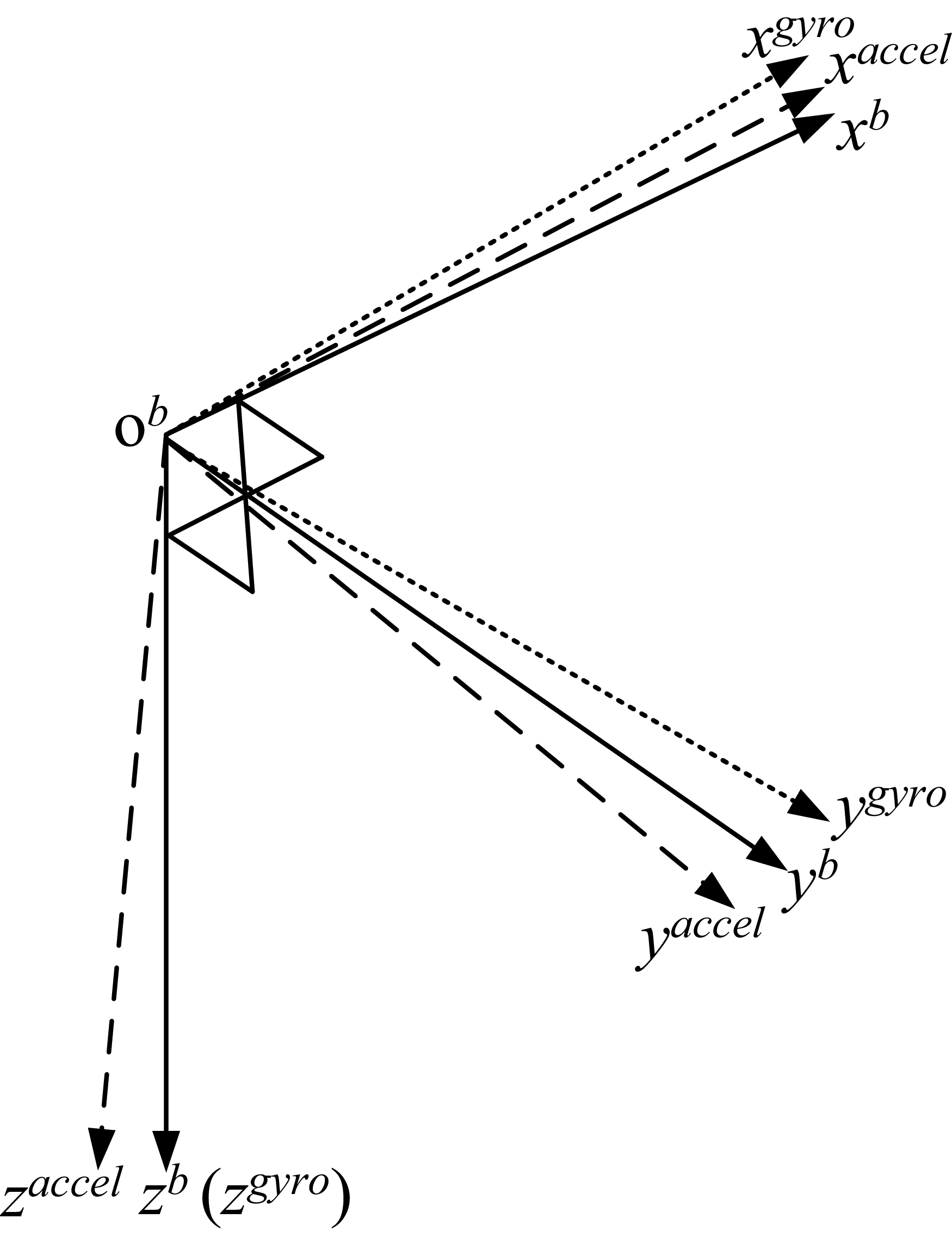
If we define the zb-axis as the sensitive axis of the z gyro and let the sensitive axis of the y gyro lie in the x–y plane of the b-frame (as shown in Figure 1), three components of gyro cross-coupling errors may be eliminated, which are δC g_xy, δC g_xz and δC g_yz. So, Equation (3) may be simplified to the following matric expression:
 $\left\{ \matrix{ \delta {\boldsymbol{\omega }}_{{\rm{scale\_cross}}}^{\rm{b}} = {{\boldsymbol{M}}_{\rm{g}}}{{\boldsymbol{\omega }}^{\rm{b}}} \hfill \cr \delta {\boldsymbol{f}}_{{\rm{scale\_cross}}}^{\rm{b}} = {{\boldsymbol{M}}_{\rm{a}}}{{\boldsymbol{\, f}}^{\rm{b}}} \hfill \cr} \right.$
where
 $\eqalign{\delta {\boldsymbol {\omega }}_{{\rm{scale\_cross}}}^{\rm{b}}{\rm{\; = \;}} {\Big[{{\delta \omega} _{{\rm{x\_scale\_cross}}}^{\rm{b}} \,{\delta \omega}} _{{\rm{y\_scale\_cross}}}^{\rm{b}} \,{\delta \omega} _{{\rm{z\_scale\_cross}}}^{\rm{b}} \Big]^{\rm{T}}}, \cr \delta {\boldsymbol {f}}_{{\rm{scale\_cross}}}^{\rm{b}} {\rm{\; = \;}}{\Big[{{\delta f_{{\rm{x\_scale\_cross}}}^{\rm{b}} \,{\delta f_{{\rm{y\_scale\_cross}}}^{\rm{b}} \,{\delta f_{{\rm{z\_scale\_cross}}}^{\rm{b}} \Big]^{\rm{T}}}},}}}}$
 ${{\boldsymbol{\omega }}^{\rm{b}}}{\rm{ = }}\left[ {\matrix{ {\omega _{\rm{x}}^{\rm{b}}} \cr {\omega _{\rm{y}}^{\rm{b}}} \cr {\omega _{\rm{z}}^{\rm{b}}} \cr } } \right],\,{{\boldsymbol{f}}^{\rm{b}}}{\rm{ = }}\left[ {\matrix{ {f_{\rm{x}}^{\rm{b}}} \cr {f_{\rm{y}}^{\rm{b}}} \cr {f_{\rm{z}}^{\rm{b}}} \cr } } \right],\,{{\boldsymbol{M}}_g}{\rm{ = }}\left[ {\matrix{ {\delta {S_{{\rm{g\_x}}}}} & 0 & 0 \cr {\delta {C_{{\rm{g\_yx}}}}} & {\delta {S_{{\rm{g\_y}}}}} & 0 \cr {\delta {C_{{\rm{g\_zx}}}}} & {\delta {C_{{\rm{g\_zy}}}}} & {\delta {S_{{\rm{g\_z}}}}} \cr } } \right],\,{{\boldsymbol{M}}_a}{\rm{ = }}\left[ {\matrix{ {\delta {S_{{\rm{a\_x}}}}} & {\delta {C_{{\rm{a\_xy}}}}} & {\delta {C_{{\rm{a\_xz}}}}} \cr {\delta {C_{{\rm{a\_yx}}}}} & {\delta {S_{{\rm{a\_y}}}}} & {\delta {C_{{\rm{a\_yz}}}}} \cr {\delta {C_{{\rm{a\_zx}}}}} & {\delta {C_{{\rm{a\_zy}}}}} & {\delta {S_{{\rm{a\_z}}}}} \cr } } \right].$
Misalignment of gyro and accelerometer sensitive axes (Groves, Reference Groves2013).

Figure 1. Long description
A diagram showing the misalignment of gyro and accelerometer sensitive axes. The diagram features a three-dimensional coordinate system with axes labeled as x, y, and z. The origin of the coordinate system is marked as O. The diagram shows three sets of axes: xb, yb, zb representing the body frame; xgyro, ygyro, zgyro representing the gyro frame; and xaccel, yaccel, zaccel representing the accelerometer frame. The axes are depicted with slight misalignments, indicating the misalignment between the gyro and accelerometer sensitive axes.
Additionally, the scale factor and cross-coupling errors are typically modelled with no deterministic time variation. Thus,
 $\left\{ {\matrix{ {{{{\boldsymbol {\dot M}}}_{\rm g}} = {\boldsymbol {0}}} \cr {{{{\boldsymbol {\dot M}}}_{\rm a}} = {\boldsymbol {0}}} \cr } } \right.$
Finally, combining Equations (1) and (4), the main error sources of the gyro and accelerometer outputs in aerial remote sensing application can be shown as the following equations:
 $\left\{ {\matrix{ {\delta {{\boldsymbol {\omega }}^{\rm b}} = {{\boldsymbol {M}}_{\rm g}}{{\boldsymbol {\omega }}^{\rm b}} + {\varepsilon _{\rm s}} + {\varepsilon _{\rm d}}} \cr {\delta {{\boldsymbol {f}}^{\rm b}} = {{\boldsymbol {M}}_{\rm a}}{{\boldsymbol {\, f}}^{\rm b}} + {\nabla _{\rm s}} + {\nabla _{\rm d}}} \cr } } \right.$
2.2. Approximate processing error modeling
First, according to the inertial navigation equations in the local-navigation frame (n-frame) (Mohinder et al., Reference Mohinder, Angus and Chri2020), the acceleration could be expressed in terms of the specific force, centrifugal acceleration and gravity,
 ${{\boldsymbol {\dot V}}^{\rm n}} = {\boldsymbol {C}}_{\rm b}^{\rm n}{{\boldsymbol {\, f}}^{\rm b}} - (2{\boldsymbol {\omega }}_{\rm ie}^{\rm n} + {\boldsymbol {\omega }}_{\rm en}^{\rm n}) \,\times \,{{\boldsymbol {V}}^{\rm n}} + {{\boldsymbol {g}}^{\rm n}}$
where V n and
 $\omega _{{\rm{ie}}}^{\rm{n}}$
are the kinematic velocity and the earth rotation vector in the n-frame;
 ${\boldsymbol \omega} _{{\rm{en}}}^{\rm{n}}$
is known as the rotating angular velocity which arises from the rotation of the n-frame axes as the frame centre moves with respect to the Earth;
 $C _{{\rm{b}}}^{\rm{n}}$
denotes the transformation matrix between b-frame and n-frame; and g n represents the gravity vector in n-frame.
Typically, we use an empirical model (WGS84) to obtain the gravity vector,
 ${\boldsymbol g} _{{\rm{m}}}^{\rm{n}}$
, which applies the scaling law to calculate the gravity value with various altitude (Manon et al., Reference Manon, Jeroen and Thomas2017),
 $\left\{ {\matrix{ {\hskip-168pt{\boldsymbol {g}}_{\rm{m}}^{\rm{n}} = {{\left( {\matrix{ 0 & 0 & \gamma \cr } } \right)}^{\rm{T}}}{\rm{ }}} \cr \matrix{ \gamma = 9.780325 \,\times\, (1 + {\rm{0}}{\rm{.005302}}\,{\sin ^2}\,L - {\rm{0}}{\rm{.0000058}}{\sin ^2}\,2L) \hfill \cr \quad \quad - ({\rm{3}}{\rm{.0877}} - {\rm{0}}{\rm{.0044}}\,{\sin ^2}\,L) \,\times\, {10^{ - 6}} \quad h + 0.072 \, \times \, {10^{ - 12}}\,{h^2} \hfill \cr} \cr } } \right.$
where γ denotes the vertical component of
 ${\boldsymbol g} _{{\rm{m}}}^{\rm{n}}$
; and L and h are latitude and altitude.
The difference between the actual and modeled gravity fields is referred to as the gravity disturbance δg n
 $\delta {{\boldsymbol {g}}^{\rm{n}}} = {{\boldsymbol {g}}^{\rm{n}}} - {\boldsymbol {g}}_{\rm{m}}^{\rm{n}}$
In common GNSS/INS application scenarios, the effects of δg n are absorbed by the z-axis accelerometer bias state and the components of the attitude error states resolved about the horizontal axes (Groves, Reference Groves2013). However, for high-precision GNSS/INS in remote sensing application, it is essential to estimate δg n as separate Kalman filter states which could be modelled as exponentially correlated fixed-variance first-order Markov processes
 $\delta {{\boldsymbol {\dot g}}^{\rm{n}}} = - {{\delta {{\boldsymbol {g}}^{\rm{n}}}} \over {{{\boldsymbol {\tau }}_{\rm g}}}} + {{\boldsymbol {w}}_{\rm g}}$
where τ g is the correlation time of the gravity disturbance and w g denotes the excitation white noise of δg n.
As gravity disturbance errors are spatially correlated rather than temporally correlated, the correlation time τ g is velocity-dependent, which can be expressed by using the presumably constant velocity of the vehicle
 $\bar V$
and the correlation distance β.
 ${\tau _{\rm g}} = \beta \bar V$
Equation (11) is substituted into Equation (10) to reorganise
 $\delta {{\boldsymbol {\dot g}}^{\rm{n}}} = - {{\delta {{\boldsymbol {g}}^{\rm{n}}}} \over {\beta \bar V}} + {{\boldsymbol {\omega }}_{\rm g}}$
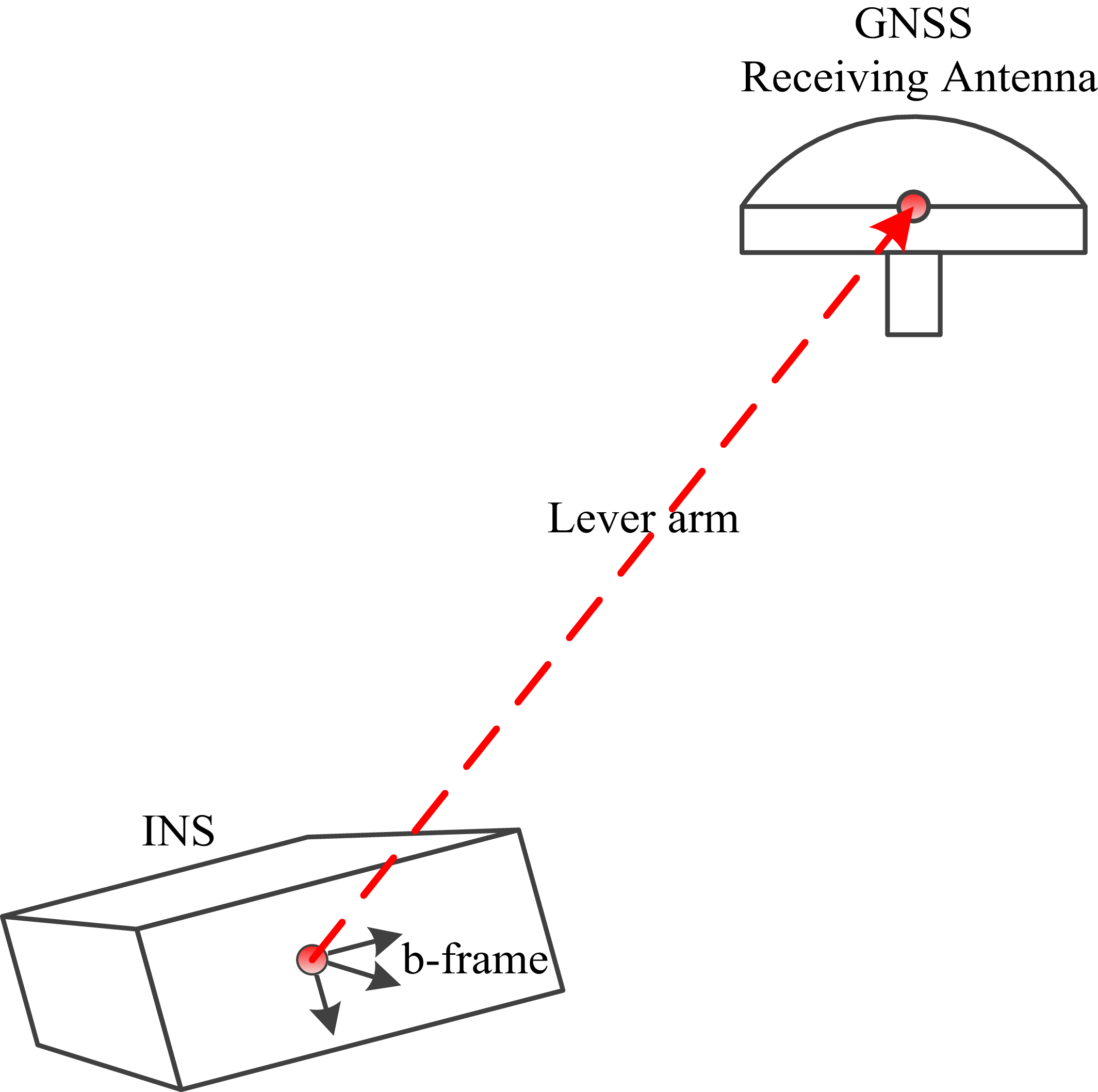
Second, the position and velocity solutions of GNSS are used as observations to estimate the INS errors. Normally, a GNSS receiving antenna needs to be mounted onto the aircraft top for good reception and INS is always fixedly connected with the remoting sensor under the airframe.
The spatial vector from INS location to GNSS receiving antenna (as shown in Figure 2), named lever arm, may bring non-negligible observation errors, which will lead to the INS/GNSS accuracy degradation. Therefore, the lever arm effect should be properly compensated that generally converts the GNSS antenna phase centre to an INS center as follows:
 $\left\{ \matrix{ {\boldsymbol {P}}_{\rm INS}^{\rm n} = {\boldsymbol {P}}_{\rm GNSS}^{\rm n} - {\boldsymbol {C}}_{\rm b}^{\rm n}{\boldsymbol {l}}_{\rm GNSS}^{\rm b} \hfill \cr {\boldsymbol {V}}_{\rm INS}^{\rm n} = {\boldsymbol {V}}_{\rm GNSS}^{\rm n} - {\boldsymbol {C}}_{\rm b}^{\rm n}\left( {{\boldsymbol {\omega }}_{\rm nb}^{\rm b} \, \times \,{\boldsymbol {l}}_{\rm GNSS}^{\rm b}} \right) \hfill \cr {\boldsymbol {A}}_{\rm INS}^{\rm n} = {\boldsymbol {A}}_{\rm GNSS}^{\rm n} - {\boldsymbol {C}}_{\rm b}^{\rm n}\left( {{\boldsymbol {\omega }}_{\rm nb}^{\rm b} \,\times \,{\boldsymbol {\omega }}_{\rm nb}^{\rm b} \, \times \,{\boldsymbol {l}}_{\rm GNSS}^{\rm b}} \right) - {\boldsymbol {C}}_{\rm b}^{\rm n}\left( {{\boldsymbol {\dot \omega }}_{\rm nb}^{\rm b} \,\times \,{\boldsymbol {l}}_{\rm GNSS}^{\rm b}} \right) \hfill \cr} \right.$
where
 ${{\boldsymbol{P}}_{{\rm{GNSS}}}^{\rm{n}}}$
,
 ${{\boldsymbol{V}}_{{\rm{GNSS}}}^{\rm{n}}}$
and
 ${{\boldsymbol{A}}_{{\rm{GNSS}}}^{\rm{n}}}$
denote the actual position, velocity and acceleration solutions in GNSS antenna phase centre. Additionally,
 ${{\boldsymbol{P}}_{{\rm{INS}}}^{\rm{n}}}$
,
 ${{\boldsymbol{V}}_{{\rm{INS}}}^{\rm{n}}}$
and
 ${{\boldsymbol{A}}_{{\rm{INS}}}^{\rm{n}}}$
denote the actual position, velocity and acceleration solutions in the INS centre. Here,
 ${{\bf{\omega }}_{{\rm{nb}}}^{\rm{b}}}$
is known as the rotating angular velocity which arises from the rotation of the b-frame axes as the frame centre moves with respect to the n-frame. Furthermore,
 ${{\boldsymbol{l}}_{{\rm{GNSS}}}^{\rm{b}}}$
denotes the actual lever arm vector of GNSS with respect to INS in the b-frame.
Schematic of lever arm.

However, if it is not practical to accurately measure the lever arm, the uncertainty may also be estimated as Kalman filter states and can be modelled as follows:
 $\left\{ \matrix{ {\boldsymbol{l}}_{{\rm{GNSS\_measure}}}^{\rm{b}} = {\boldsymbol{l}}_{{\rm{GNSS}}}^{\rm{b}} + \delta {{\boldsymbol{l}}^{\rm{b}}} \hfill \cr \dot \delta {{\boldsymbol{l}}^{\rm{b}}} = 0 \hfill \cr} \right.$
where
 ${\boldsymbol{l}}_{{\rm{GNSS\_measure}}}^{\rm{b}}$
denotes the measured lever arm and δl denotes the lever arm uncertainty.
3. High-dimensional system error model and real-time estimation scheme
3.1. System error model and state selection
For GNSS/INS integration, the system error model depends on the Kalman filter states, and closely correlates with the integration architecture, coordinate systems used in navigation, inertial sensor errors, approximate calculation errors and application scenario (Groves, Reference Groves2013). The most prevalently used GNSS/INS integration architecture in remote sensing application is the loosely coupled scheme because of its simplicity that applies to any INS and GNNS equipment. In n-frame, the coordinate axes are aligned with the topographic directions, such as east (E), north (N) and up (U), and the error propagation equations of INS navigation are given as follows:
 $\left\{ {\matrix{ \hskip-89pt{\delta \dot L = - {{{V_{\rm{N}}} \, \cdot \, \delta h} \over {{{({R_{\rm m}} + h)}^2}}}{\rm{ + }}{{\delta {V_{\rm{N}}}} \over {{R_{\rm m}} + h}}{\rm{,}}\delta \dot h = \delta {V_{\rm U}}{\rm{ }}} \cr \hskip-55pt{\delta \dot \lambda = {{{V_{\rm{E}}}\, \cdot \, \sec L\, \cdot \, \tan L\, \cdot \, \delta L} \over {{R_{\rm n}} + h}} - {{{V_{\rm{E}}}\, \cdot \, \sec L\, \cdot \, \delta h} \over {{{({R_{\rm n}} + h)}^2}}} + {{\sec L\, \cdot \, \delta {V_{\rm{E}}}} \over {{R_{\rm n}} + h}}} \cr \matrix{ \delta {{{\boldsymbol {\dot V}}}^{\rm n}} = {\boldsymbol {C}}_{\rm b}^{\rm n} \cdot \delta {{\boldsymbol {f}}^{\rm b}} - {{\boldsymbol {\psi }}^{\rm n}} \; \times \; ({\boldsymbol {C}}_{\rm b}^{\rm n} \cdot {{\boldsymbol {f}}^{\rm b}}) - (2{\boldsymbol {\omega }}_{\rm ie}^{\rm n} + {\boldsymbol {\omega }}_{\rm en}^{\rm n}) \; \times \; \delta {{\boldsymbol {V}}^{\rm n}} \hfill \cr \quad \quad \quad + (2\delta {\boldsymbol \omega }_{\rm ie}^{\rm n} + \delta {\boldsymbol \omega} _{\rm en}^{\rm n}) \; \times \; {V^{\rm n}} + \delta {\boldsymbol g^{\rm n}} \hfill \cr} \cr \hskip-19pt{{{{\boldsymbol {\dot \psi }}}^{\rm n}} = {\boldsymbol {C}}_{\rm b}^{\rm n} \cdot \delta {{\boldsymbol {\omega }}^{\rm b}} + {{\boldsymbol {\psi }}^{\rm n}}\, \times \,({\boldsymbol {\omega }}_{\rm ie}^{\rm n} + {\boldsymbol {\omega }}_{\rm en}^{\rm n}) + \delta {\boldsymbol {\omega }}_{\rm ie}^{\rm n} + \delta {\boldsymbol {\omega }}_{\rm en}^{\rm n}{\rm{ }}} \cr } } \right.$
where λ denotes longitude; R m and R n denote the main curvature radius of meridian and prime vertical; V n = [V E V N V U]T denotes the velocity vector in the n-frame; ψ n = [ψ E ψ N ψ U]T denotes the attitude misalignment vector in the n-frame; and
 ${\boldsymbol {C}}_{\rm b}^{\rm n}$
= [C 11 C 12 C 13; C 21 C 22 C 23; C 31 C 32 C 33] denotes the transformation matrix between the b-frame and n-frame.
For the GNSS/INS integration with a loosely coupled scheme, the core partition of the system state vector comprises the position/velocity/attitude errors shown in the left-hand side of Equation (15). The choice of other error states to estimate depends on their effect on the GNSS/INS integrated navigation solution. The accelerometer biases and gravity disturbance errors should be estimated because the attitude error estimations would be contaminated by the effects of them. The gyro biases produce a quadratic increase of velocity error with the elapse of time, which should be also estimated. With a circular or oval trajectory, the scale factor and cross-coupling errors will result in an oscillating attitude error, and their inclusion in the system state vector can effectively improve the estimation of the accelerometer and gyro biases. The lever arm errors in the aircraft platform of the remote sensing application obviously exceed the cm-level error in GNSS measurement, which should also be included as the system states. Therefore, a system error model of GNSS/INS is developed here for estimating position, velocity and attitude errors referenced to the n-frame, together with inertial sensor errors and approximate processing errors. The state vector X consists of 42 error states such that X = [δL δλ δh δV E δV N δV U ψ E ψ N ψ U∇ dx∇ dy∇ dz ε dx ε dy ε dz δg E δg N δg U∇ sx∇ sy∇ sz δS a_x δS a_y δS a_z δC a_xy δC a_xz δC a_yx δC a_yz δC a_zx δC a_zy ε sx ε sy ε sz δS g_x δS g_y δS g_z δC g_yx δC g_zx δC g_zy δl x δl y δl z]T.
Based on INS error propagations, inertial sensor error models and approximate calculation error models, the system state equation for Kalman filter state estimation, at time, t, is given as
 ${\boldsymbol {\dot X}}(t) = {\boldsymbol {F}}(t) \cdot {\boldsymbol {X}}(t) + {\boldsymbol {G}}(t) \cdot {\boldsymbol {w}}(t)$
where F is the 42-dimensional system matrix and G is the system noise distribution matrix with 42×9 dimensions. The specific forms of F and G can be derivable from Equations (6), (10), (14) and (15). Here, w is the 9-dimensional system noise vector.
3.2. Optimal state estimation scheme with high-efficiency Kalman filter
The transition matrix Φk/k–1 is derived from the power-series expansion of system matrix F and propagation interval T,
 ${{\boldsymbol {\Phi }}_{k/k - 1}} = \sum\limits_{r = 0}^{ + \infty } {{{{\boldsymbol {F}}_{k - 1}^r{T^r}} \over {r!}}} $
where F k–1 can be calculated by (F(t–T) + F(t))/2.
The differences between measurements output by INS and GNSS are taken as the observation vector Zk, and the discrete-time state-space model is as shown in the following equations:
 $\left\{ {\matrix{ {{{\boldsymbol {X}}_k} = {{\boldsymbol {\Phi }}_{k/k - 1}}{{\boldsymbol {X}}_{k - 1}} + {{\boldsymbol {W}}_{k - 1}}} \cr {\hskip-30pt{{\boldsymbol {Z}}_k} = {{\boldsymbol {H}}_k} \cdot {{\boldsymbol {X}}_k} + {{\boldsymbol {v}}_k}{\rm{ }}} \cr } } \right.$
where vk denotes the observation noise vector, whose components are considered as zero-mean random white noise. Additionally, W k–1 is the discrete system noise vector such that
 ${{\boldsymbol{W}}_{k - 1}} = \int_{t - T}^t {{{\boldsymbol{\Phi }}_{k/k - 1}}{\boldsymbol{G}}({{\tau }})} {\boldsymbol{w}}({{\tau }}){{d\tau }}$
Here, Z is derived from the difference of position, velocity and acceleration solutions between INS and GNSS, calculated as
 ${\boldsymbol {Z}} = \left[ {\matrix{ {\delta {{\boldsymbol {P}}^{\rm n}} + {\boldsymbol {C}}_{\rm b}^{\rm n}{\boldsymbol {l}}_{\rm GNSS}^{\rm b} \times {{\boldsymbol {\psi }}^{\rm n}} + {\boldsymbol {C}}_{\rm b}^{\rm n}\delta {{\boldsymbol {l}}^{\rm{b}}}} \cr {\delta {{\boldsymbol {V}}^{\rm n}} + {\boldsymbol {C}}_{\rm b}^{\rm n}{\boldsymbol {\omega }}_{\rm nb}^{\rm b} \times {\boldsymbol {l}}_{\rm GNSS}^{\rm b} \times {{\boldsymbol {\psi }}^{\rm n}} + {\boldsymbol {C}}_{\rm b}^{\rm n}{\boldsymbol {\omega }}_{\rm nb}^{\rm b} \times \delta {{\boldsymbol {l}}^{\rm{b}}}} \cr \matrix{ ({\boldsymbol {C}}_{\rm b}^{\rm n}{{\boldsymbol {f}}^{\rm b}} + {\boldsymbol {C}}_{\rm b}^{\rm n}\left( {{\boldsymbol {\omega }}_{\rm nb}^{\rm b} \times {\boldsymbol {\omega }}_{\rm nb}^{\rm b} + {\boldsymbol {\dot \omega }}_{\rm nb}^{\rm b}} \right) \times {\boldsymbol {l}}_{\rm GNSS}^{\rm b}) \times {{\boldsymbol {\psi }}^{\rm n}} + {\boldsymbol {C}}_{\rm b}^{\rm n}\delta {{\boldsymbol {f}}^{\rm{b}}} \hfill \cr \hskip45pt + \delta {{\boldsymbol {g}}^{\rm{n}}} + {\boldsymbol {C}}_{\rm b}^{\rm n}\left( {{\boldsymbol {\omega }}_{\rm nb}^{\rm b} \times {\boldsymbol {\omega }}_{\rm nb}^{\rm b} + {\boldsymbol {\dot \omega }}_{\rm nb}^{\rm b}} \right) \times \delta {{\boldsymbol {l}}^{\rm{b}}} \hfill \cr} \cr } } \right]{\rm{ + }}{\boldsymbol {v}}$
Thus, the specific forms of the observation matrix H are defined as follows:
 $\left\{ \matrix{ {\boldsymbol {H}} = \left[ {\matrix{ {{{\boldsymbol {I}}_{3 \! \times \! 3}}} & {{{\boldsymbol {0}}_{3\! \times \! 3}}} & {{\boldsymbol {H}}1} & {{{\boldsymbol {0}}_{3\! \times \! 3}}} & {{{\boldsymbol {0}}_{3\! \times \! 3}}} & {{{\boldsymbol {0}}_{3\! \times \! 3}}} & {{{\boldsymbol {0}}_{3\! \times \! 3}}} & {{{\boldsymbol {0}}_{3\! \times \! 3}}} & {{{\boldsymbol {0}}_{3\! \times \! 6}}} & {{{\boldsymbol {0}}_{3\! \times \! 9}}} & {{\boldsymbol {C}}_{\rm b}^{\rm n}} \cr {{{\boldsymbol {0}}_{3\! \times \! 3}}} & {{{\boldsymbol {I}}_{3\! \times \! 3}} } & {{\boldsymbol {H}}2} & {{{\boldsymbol {0}}_{3\! \times \! 3}}} & {{{\boldsymbol {0}}_{3\! \times \! 3}}} & {{{\boldsymbol {0}}_{3\! \times \! 3}}} & {{{\boldsymbol {0}}_{3\! \times \! 3}}} & {{{\boldsymbol {0}}_{3\! \times \! 3}}} & {{{\boldsymbol {0}}_{3\! \times \! 6}}} & {{{\boldsymbol {0}}_{3\! \times \! 9}}} & {{\boldsymbol {H}}6} \cr {{{\boldsymbol {0}}_{3\! \times \! 3}}} & {{{\boldsymbol {0}}_{3\! \times \! 3}}} & {{\boldsymbol {H}}3} & {{\boldsymbol {C}}_{\rm b}^{\rm n}} & {{{\boldsymbol {0}}_{3\! \times \! 3}}} & { {{\boldsymbol {I}}_{3\! \times \! 3}}{\rm{ }}} & {{\boldsymbol {C}}_{\rm b}^{\rm n}{\rm{ }}} & {{\boldsymbol {H}}4} & {{\boldsymbol {H}}5} & {{{\boldsymbol {0}}_{3\! \times \! 9}}} & {{\boldsymbol {H}}7} \cr } } \right] \hfill \cr {\boldsymbol {H}}1{\rm{\; = \; }}{\boldsymbol {C}}_{\rm b}^{\rm n}\left[ {{\boldsymbol {l}}_{\rm GNSS}^{\rm b} \times } \right] \quad{\boldsymbol {H}}2{\rm{ = }}{\boldsymbol {C}}_{\rm b}^{\rm n}\left[ {{\boldsymbol {\omega }}_{\rm nb}^{\rm b} \times {\boldsymbol {l}}_{\rm GNSS}^{\rm b} \times } \right] \hfill \cr {\boldsymbol {H}}3{\rm{ \; = \; }}{\boldsymbol {C}}_{\rm b}^{\rm n}\left[ {{{\boldsymbol {f}}^{\rm b}} \times } \right] + {\boldsymbol {C}}_{\rm b}^{\rm n}\left[ {\left( {\boldsymbol\omega _{\rm nb}^{\rm b} \times \omega _{\rm nb}^{\rm b} + {\boldsymbol {\dot \omega }}_{\rm nb}^{\rm b}} \right) \times {\boldsymbol {l}}_{\rm GNSS}^{\rm b} \times } \right] \hfill \cr {\boldsymbol {H}}4{\rm{\; = \; }}{\boldsymbol {C}}_{\rm b}^{\rm n}\left[ {\matrix{ {f_{\rm x}^{\rm b}} & 0 & 0 \cr 0 & {f_{\rm y}^{\rm b}} & 0 \cr 0 & 0 & {f_{\rm z}^{\rm b}} \cr } } \right] \quad{\boldsymbol {H}}5{\rm{\; = \; }}{\boldsymbol {C}}_{\rm b}^{\rm n}\left[ \matrix{ f_{\rm y}^{\rm b}& {\rm{ }}f_{\rm z}^{\rm b}& 0 & 0& 0& 0 \hfill \cr {\rm{0}}& 0 & f_{\rm x}^{\rm b}& {\rm{ }}f_{\rm z}^{\rm b}& {\rm{ 0}}& 0 \hfill \cr {\rm{0}}& 0& 0& 0& f_{\rm x}^{\rm b}& {\rm{ }}f_{\rm y}^{\rm b} \hfill \cr} \right] \hfill \cr {\boldsymbol {H}}6{\rm{\; = \; }}{\boldsymbol {C}}_{\rm b}^{\rm n}\left[ {{\boldsymbol {\omega }}_{\rm nb}^{\rm b} \times } \right] \quad{\boldsymbol {H}}7{\rm{ \; = \; }}{\boldsymbol {C}}_{\rm b}^{\rm n}\left[ {\left( {{\boldsymbol {\omega }}_{\rm nb}^{\rm b} \times {\boldsymbol {\omega }}_{\rm nb}^{\rm b} + {\boldsymbol {\dot \omega }}_{\rm nb}^{\rm b}} \right) \times } \right] \hfill \cr} \right.$
where [*×] denotes the anti-symmetric matrix of vector *.
The state vector estimation
 ${\hat X}$
k is solved according to the discrete-time Kalman filter algorithm, as
 $\left\{ {\matrix{ {\hskip-110pt{{{\boldsymbol {\hat X}}}_{k/k - 1}} = {{\boldsymbol {\Phi }}_{k/k - 1}}{{{\boldsymbol {\hat X}}}_{k - 1}}{\rm{ }}} \cr {\hskip-52pt{{{\boldsymbol {\hat X}}}_k} = {{{\boldsymbol {\hat X}}}_{k/k - 1}} + {{\boldsymbol {{\boldsymbol K}}}_k}({{\boldsymbol {Z}}_k} - {{\boldsymbol {H}}_k}{{{\boldsymbol {\hat X}}}_{k/k - 1}}){\rm{ }}} \cr {\hskip-40pt{{\boldsymbol {{K}}}_k} = {{\boldsymbol {P}}_{k/k - 1}}{\boldsymbol {H}}_k^{\rm{T}}{{({{\boldsymbol {H}}_k}{{\boldsymbol {P}}_{k/k - 1}}{\boldsymbol {H}}_k^{\rm{T}} + {{\boldsymbol {R}}_k})}^{ - 1}}{\rm{ }}} \cr {\hskip-50pt{{\boldsymbol {P}}_{k/k - 1}} = {{\boldsymbol {\Phi }}_{k/k - 1}}{{\boldsymbol {P}}_{k - 1}}{\boldsymbol {\Phi }}_{k/k - 1}^{\rm{T}} + {\boldsymbol {Q}_{k - 1}}{\rm{ }}} \cr {{{\boldsymbol {P}}_k} = ({\boldsymbol {{I}}} - {{\boldsymbol {{K}}}_k}{{\boldsymbol {H}}_k}){{\boldsymbol {P}}_{k/k - 1}}{{({\boldsymbol {{I}}} - {{\boldsymbol {{K}}}_k}{{\boldsymbol {H}}_k})}^{\rm{T}}} + {{\boldsymbol {{K}}}_k}{{\boldsymbol {R}}_k}{\boldsymbol {K}}_k^{\rm{T}}} \cr } } \right.$
where Kk and Pk represent the Kalman gain matrix and the error covariance matrix. Here, Rk and Qk are the measurement noise covariance matrix and the system noise covariance matrix, which are determined by the following equation:
 $\left\{ {\matrix{ {\hskip-10pt{{\boldsymbol {R}}_k} = E\left[ {{{\boldsymbol {v}}_k}{\boldsymbol {v}}_k^{\rm{T}}} \right]} \cr {{{\boldsymbol {Q}}_k} = E\left[ {{{\boldsymbol {W}}_k}{\boldsymbol {W}}_k^{\rm{T}}} \right]} \cr } } \right.$
In Equation (22), the computation burden of propagating the error covariance matrix P k/k–1 is most heavy, which holds more than 70% of the computation time in the whole Kalman filter process (Ca et al., Reference Ca, Fang and Shen2006). Additionally,
 ${{{\boldsymbol{\Phi }}_{k/k - 1}}{{\boldsymbol{P}}_{k - 1}}{\boldsymbol{\Phi }}_{k/k - 1}^{\rm{T}}}$
is the core part of the P k/k–1 calculation, which requires 2N 3 multiplications and N 2 temporary variables with the conventional matrix dot-product (N represents the dimensionality of the system states). Therefore, efforts to achieve speed optimisation of the Kalman filter should focus on reducing the computation burden of
 ${{{\boldsymbol{\Phi }}_{k/k - 1}}{{\boldsymbol{P}}_{k - 1}}{\boldsymbol{\Phi }}_{k/k - 1}^{\rm{T}}}$
. To ensure as much GNSS/INS accuracy as possible, the commonly used dimension-reduction method will not be taken into account. In this study, due to large amount of zero elements contained in the transition matrix, Φ k/k–1 can be used to construct an obvious sparse matrix. From Equation (17), the value of T is set to ten milliseconds according to the IMU sampling frequency in our study, so the power series can be limited to the first order in F k–1, and the transition matrix Φ k/k–1 is
 ${{\boldsymbol {\Phi }}_{k/k - 1}} = \left[ {\matrix{ {{\boldsymbol {\Phi }}{1_{9\times9}}} & {{\boldsymbol {\Phi }}{2_{9\times 9}}} & {{\boldsymbol {\Phi }}{3_{9\times 24}}} \cr {{{\bf {0}}_{9\times9}}} & {{\boldsymbol {\Phi }}{4_{9\times9}}} & {{{\bf {0}}_{9\times24}}} \cr {{{\bf {0}}_{24\times9}}} & {{{\bf {0}}_{24\times9}}} & {{{\boldsymbol {{I}}}_{24\times24}}} \cr } } \right]$
Since the error covariance matrix is symmetric about the diagonal, P k–1 may be partitioned as
 ${{\boldsymbol {P}}_{k - 1}} = \left[ {\matrix{ {{\boldsymbol {P}}{1_{9\times9}}} & {{\boldsymbol {P}}{2_{9\times9}}} & {{\boldsymbol {P}}{3_{9\times24}}} \cr {{\boldsymbol {P}}2_{9\times9}^{\rm{T}}} & {{\boldsymbol {P}}{4_{9\times9}}} & {{\boldsymbol {P}}{5_{9\times24}}} \cr {{\boldsymbol {P}}3_{24\times9}^{\rm{T}}} & {{\boldsymbol {P}}5_{24\times9}^{\rm{T}}} & {{\boldsymbol {P}}{6_{24 \times24}}} \cr } } \right]$
From Equations (24) and (25),
 ${{{\bf{\Phi }}_{k/k - 1}}{{\boldsymbol{P}}_{k - 1}}{\bf{\Phi }}_{k/k - 1}^{\rm{T}}}$
becomes
 $\eqalign{ & {{\boldsymbol {\Phi }}_{k/k - 1}}{{\boldsymbol {P}}_{k - 1}}{\boldsymbol {\Phi }}_{k/k - 1}^{\rm{T}} = \cr & {\rm{ }}\left[ {\matrix{ {{{\left( \matrix{ {\boldsymbol {\Phi }}1{\boldsymbol {P}}1{\boldsymbol {\Phi }}{1^{\rm{T}}} + {\boldsymbol {\Phi }}2{\boldsymbol {P}}4{\boldsymbol {\Phi }}{2^{\rm{T}}} + {\boldsymbol {\Phi }}3{\boldsymbol {P}}6{\boldsymbol {\Phi }}{3^{\rm{T}}} \hfill \cr + {\boldsymbol {\Phi }}1{\boldsymbol {P}}2{\boldsymbol {\Phi }}{2^{\rm{T}}} + {\left( {{\boldsymbol {\Phi }}1{\boldsymbol {P}}2{\boldsymbol {\Phi }}{2^{\rm{T}}}} \right)^{\rm{T}}} \hfill \cr {\rm{ + }}{\boldsymbol {\Phi }}1{\boldsymbol {P}}3{\boldsymbol {\Phi }}{3^{\rm{T}}} + {\left( {{\boldsymbol {\Phi }}1{\boldsymbol {P}}3{\boldsymbol {\Phi }}{3^{\rm{T}}}} \right)^{\rm{T}}} \hfill \cr + {\boldsymbol {\Phi }}2{\boldsymbol {P}}5{\boldsymbol {\Phi }}{3^{\rm{T}}} + {\left( {{\boldsymbol {\Phi }}2{\boldsymbol {P}}5{\boldsymbol {\Phi }}{3^{\rm{T}}}} \right)^{\rm{T}}} \hfill \cr} \right)}_{\!9\!\times\!9}}} & {{{\left( \matrix{ {\boldsymbol {\Phi }}1{\boldsymbol {P}}2{\boldsymbol {\Phi }}{4^{\rm{T}}} \hfill \cr + {\boldsymbol {\Phi }}2{\boldsymbol {P}}4{\boldsymbol {\Phi }}{4^{\rm{T}}} \hfill \cr + {\boldsymbol {\Phi }}3{\boldsymbol {P}}{5^{\rm{T}}}{\boldsymbol {\Phi }}{4^{\rm{T}}} \hfill \cr} \right)}_{\!9\!\times\!9}}} & {{{\left( \matrix{ {\boldsymbol {\Phi }}1{\boldsymbol {P}}3 \hfill \cr + {\boldsymbol {\Phi }}2{\boldsymbol {P}}5 \hfill \cr + {\boldsymbol {\Phi }}3{\boldsymbol {P}}6 \hfill \cr} \right)}_{\!9\!\times\!24}}} \cr {{{\left( \matrix{ {\boldsymbol {\Phi }}1{\boldsymbol {P}}2{\boldsymbol {\Phi }}{4^{\rm{T}}} \hfill \cr + {\boldsymbol {\Phi }}2{\boldsymbol {P}}4{\boldsymbol {\Phi }}{4^{\rm{T}}} \hfill \cr + {\boldsymbol {\Phi }}3{\boldsymbol {P}}{5^{\rm{T}}}{\boldsymbol {\Phi }}{4^{\rm{T}}} \hfill \cr} \right)}^{\rm{\!\!T}}}_{9\!\times\!9}} & {{{\left( {{\boldsymbol {\Phi }}4{\boldsymbol {P}}4{\boldsymbol {\Phi }}{4^{\rm{T}}}} \right)}_{9\!\times\!9}}} & {{{\left( {{\boldsymbol {\Phi }}4{\boldsymbol {P}}5} \right)}_{9\!\times\!24}}} \cr {{{\left( \matrix{ {\boldsymbol {\Phi }}1{\boldsymbol {P}}3 \hfill \cr + {\boldsymbol {\Phi }}2{\boldsymbol {P}}5 \hfill \cr + {\boldsymbol {\Phi }}3{\boldsymbol {P}}6 \hfill \cr} \right)}^{\!\! \rm{T}}}_{24\!\times\!9}} & {{{\left( {{\boldsymbol {\Phi }}4{\boldsymbol {P}}5} \right)}^{\rm{T}}}_{24\!\times\!9}} & {{\boldsymbol {P}}{6_{24\!\times\!24}}} \cr } } \right] \cr} $
In Equation (26),
 ${{{\bf{\Phi }}_{k/k - 1}}{{\boldsymbol{P}}_{k - 1}}{\bf{\Phi }}_{k/k - 1}^{\rm{T}}}$
is obviously symmetric about the diagonal and displays much repetition calculation. To optimise the tradeoff between multiplication burden and temporary variables space, the computation methods for these matrix multiplications can be divided into two categories. One is the conventional matrix product method, which is used for the asymmetric structure cases, such as {Φ1P2Φ2T, Φ1P3Φ3T, Φ2P5Φ3T, Φ1P2Φ4T, Φ2P4Φ4T, Φ3P5TΦ4T, Φ1P3, Φ2P5, Φ3P6, Φ4P5}. This method requires relatively little multiplication computation, but needs to occupy a certain amount of temporary variables space.
 ${( * )_{ij}} = \sum\limits_{k = 1}^q {{{\boldsymbol {\Phi }}_{ik}}{{\boldsymbol {P}}_{kj}}} $
where (*)ij denotes the element of ith row and jth column in the result matrix; and q denotes the order of P2, P3, P4, P5 and P6. Each of {Φ19×9P29×9
 ${\boldsymbol \Phi} 2_{9 \times 9}^{\rm T}$
, Φ29×9P49×9
 ${\boldsymbol \Phi} 4_{9 \times 9}^{\rm T}$
and Φ19×9P29×9
 ${\boldsymbol \Phi} 4_{9 \times 9}^{\rm T}$
} requires 1,458 multiplications and 81 temporary variables. Then, each of {Φ19×9P39×24
 ${\boldsymbol \Phi} 3_{24 \times 9}^{\rm T}$
and Φ29×9P59×24
 ${\boldsymbol \Phi} 3_{24 \times 9}^{\rm T}$
} requires 7,128 multiplications and 216 temporary variables. Additionally, Φ39×24
 $P 5_{24 \times 9}^{\rm T}$
 ${\boldsymbol \Phi} 4_{9 \times 9}^{\rm T}$
requires 2,673 multiplications and 81 temporary variables. Finally, each of {Φ19×9P39×24, Φ29×9P59×24 and Φ49×9P59×24} requires 1944 multiplications, and Φ39×24P624×24 requires 5,184 multiplications.
The other one is the matrix exterior-product method, which is used for the symmetric structure cases, such as {Φ1P1Φ1T, Φ2P4Φ2T, Φ3P6Φ3T, Φ4P4Φ4T}. Compared with the former, this method has a higher multiplication computational cost, but requires no temporary variables space.
 ${( * )_{ij}} = \sum\limits_{k = 1}^q {{P_{kk}}{{\it{ \Phi }}_{ik}}{{\it \Phi} _{jk}}} + \sum\limits_{m = 1}^{q - 1} {\sum\limits_{k = m + 1}^q {{P_{mk}}({{\it \Phi} _{im}}{{\it \Phi}_{jk}} + } } {{\it \Phi} _{ik}}{{\it \Phi} _{jm}})$
where (*)ij denotes the element of ith row and jth column in the result matrix; and q denotes the order of P1, P4 and P6. Each of {Φ19×9P19×9
 ${\boldsymbol\Phi} 1_{9 \times 9}^T$
, Φ29×9P49×9
 ${\boldsymbol\Phi} 2_{9 \times 9}^T$
, Φ49×9P49×9
 ${\boldsymbol\Phi }4_{9 \times 9}^T$
} requires 5,670 multiplications, and Φ39×24P624×24
 ${\boldsymbol\Phi} 3_{24 \times 9}^T$
requires 38,070 multiplications. Additionally, all of them have no need for temporary variables.
It is obvious from Table 1 that the proposed approach can significantly improve the computational efficiency. Ascribing to the comprehensive use of matrix sparsity and symmetry, the computational effort required to calculate
 ${{{\bf{\Phi }}_{k/k - 1}}{{\boldsymbol{P}}_{k - 1}}{\bf{\Phi }}_{k/k - 1}^{\rm{T}}}$
can be almost halved, when the system state dimension is selected as 42. Furthermore, implementing the matrix exterior-product for the symmetrical matrix multiplications can also reduce the storage load by over 57%.
Multiplications and temporary variables requirement (system state dimension N = 42).

Table 1. Long description
A table comparing two computational approaches for matrix calculations. The table has three columns: Calculation, Multiplications required, and Temporary variables required. It has two rows of data under the calculation column: Conventional computation approach and Proposed computation approach. The conventional approach requires 148,176 multiplications and 1,764 temporary variables. The proposed approach, which uses matrix sparsity, symmetry, and exterior-product, requires 87,399 multiplications and 756 temporary variables.
4. Experiment
To validate the proposed method, an aerial mapping experiment was conducted on an airplane platform equipped with the GNSS/INS integrated system. The flight experiment data were collected and processed jointly by Beihang University and Guizhou Institute of Technology.
4.1. Hardware configuration
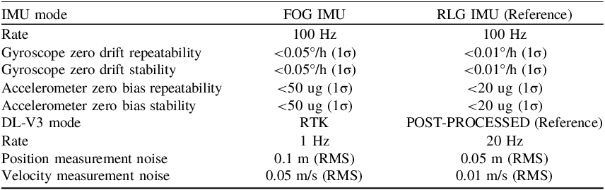
The INS and GNSS data are acquired from two different GNSS/INS integrated systems containing a fibre optic gyroscope (FOG) IMU, a ring laser gyroscope (RLG) IMU, and two NovATel DL-V3 GNSS receivers. The two IMUs are fixed on the same mounting plate as shown in Figure 3, and the IMUs and GNSS specifications are listed in Table 2. The higher-precision GNSS/RLG_INS integrated system is used as the reference system and, meanwhile, the navigation solutions provided by the GNSS/FOG_INS integrated system are used to verify the performance of the proposed method.
Equipment installation.

Specifications of FOG IMU, RLG IMU and DL-V3 GNSS receiver.

Table 2. Long description
A table comparing specifications of FOG IMU, RLG IMU, and DL-V3 GNSS receiver. The table has 10 rows and 3 columns. Column headers are IMU mode, FOG IMU, and RLG IMU (Reference). Row 1: Rate, 100 Hz, 100 Hz. Row 2: Gyroscope zero drift repeatability, less than 0.05 degrees per hour (1 sigma), less than 0.01 degrees per hour (1 sigma). Row 3: Gyroscope zero drift stability, less than 0.05 degrees per hour (1 sigma), less than 0.01 degrees per hour (1 sigma). Row 4: Accelerometer zero bias repeatability, less than 50 microg (1 sigma), less than 20 microg (1 sigma). Row 5: Accelerometer zero bias stability, less than 50 microg (1 sigma), less than 20 microg (1 sigma). Row 6: DL-V3 mode, RTK, POST-PROCESSED (Reference). Row 7: Rate, 1 Hz, 20 Hz. Row 8: Position measurement noise, 0.1 meters (RMS), 0.05 meters (RMS). Row 9: Velocity measurement noise, 0.05 meters per second (RMS), 0.01 meters per second (RMS).
4.2. Experimental arrangement
The flight experiment was conducted in Yangling, Shanxi Province, China, which lasted for approximately 1.2 hours. Before entering the survey region, the aircraft is designed to undergo a figure-of-eight manoeuvring to observe the heading error, and separate the roll and pitch errors from the horizontal accelerometer biases. During the execution of a figure-of-eight manoeuvring, a preliminary acceleration to 1.2∼1.5 times the level cruising speed is needed to establish an adequate kinetic energy reserve prior to entry. The roll angle is typically maintained within a range of 15°–20° to generate the requisite centripetal force. Simultaneously, the pitch angle is moderately increased to approximately 8° to compensate for the loss of the vertical component of lift, thereby maintaining a constant altitude. The whole flight trajectory within the reference coordinates is shown in Figure 4.
Trajectory of flight.

4.3. Experiment data processing and results analysis
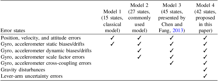
The GNSS measurements were post-processed using GrafNavTM 8.30 software (NovAtel Inc.) in carrier phase difference mode with 0.05 m level position accuracy and 0.01 m/s level velocity accuracy, and the reference trajectories were generated by the RLG IMU/Post Processed GNSS integration using InertialExplorerTM 8.30 post-processing software (NovAtel Inc.) with 0.005°/0.0025° level heading/attitude accuracy. Then, the RTK GNSS measurements were output directly by a DL-V3 receiver with 0.1 m level position accuracy and 0.05 m/s level velocity accuracy, and FOG IMU data and RTK GNSS data were integrated and processed by POSProcessTM 3.0 (GNSS/INS Research Group, Beihang University and Guizhou Institute of Technology) for the loose coupling with the following various stochastic models. The specific configurations of various stochastic models are listed in Table 3.
Configurations of various stochastic models.

Table 3. Long description
A table comparing error states across four stochastic models. The table has 8 rows and 4 columns. The columns are labeled Model 1 (15 states, classical model), Model 2 (27 states, commonly used model), Model 3 (45 states, presented by Chen and Fang, 2013), and Model 4 (42 states, proposed in this paper). The rows list different error states: Position, velocity, and attitude errors; Gyro, accelerometer static biases/drifts; Gyro, accelerometer dynamic biases/drifts; Gyro, accelerometer scale factor errors; Gyro, accelerometer cross-coupling errors; Gravity disturbances; Lever-arm uncertainty errors. Each cell indicates the presence or absence of error states in each model.
The position and velocity solution are initialised from GNSS, and self-alignment is used to initialise the heading, pitch and roll. In the state initialisation of GNSS/INS integration according to Equation (22), the state estimates X 0 should generally be initialised at zero. The initial error covariance P 0, which reflects the state uncertainties and any covariance between state residuals, is assumed using the prior knowledge of GNSS and INS performance parameters, and the measurement noise covariance matrix R and the system noise covariance matrix Q are determined based on device specifications in Table 2.
To verify the feasibility of the proposed stochastic model embedded in the GNSS/INS Kalman filter, the error states estimations were contrasted and analysed as follows. Figures 5 and 6 show the estimated static biases and drifts of accelerometer and gyro with three stochastic models. For model 1, the static bias and drift estimations vibrate intensely with the different flight strips in opposite directions, which means that model 1 is not capable for the fine description of GNSS/INS Kalman filter states and error covariance matrix varying with time. The behaviour of model 2 has improved significantly compared with model 1, but the estimation results are still not sufficiently ideal, i.e. the estimations of accelerometer three axes static bias and gyro Z-axis static drift are greater than 200 ug and 0.1°/h. Although achieving better results than model 2, model 3 has not yielded the expected results. The proposed model 4 has the best performance among the four stochastic models where the estimated accelerometer biases for three axes are approximately 40 ug, 80 ug, 90 ug, and the estimated gyro drifts for three axes are approximately 0.03°/h, 0.06°/h, 0.04°/h, respectively. The estimated static biases/drifts of accelerometer/gyro with the proposed model 4 are very close to the nominal value in Table 2.
Estimated acce. static biases comparison of models 1, 2, 3 and 4.

Figure 5. Long description
Three line graphs depict the comparison of estimated acceleration static biases for four models. Panel A: The line graph shows acceleration static bias estimation in the X-axis. The horizontal axis represents time in milliseconds, ranging from approximately 5.365 to 5.410 times 10^4. The vertical axis represents acceleration static bias estimation in micro-g, ranging from -1500 to 1500. Four models are compared: model 1 in red, model 2 in blue, model 3 in black, and model 4 in green. Model 1 shows significant fluctuations, while models 2, 3, and 4 exhibit more stable trends. Panel B: The line graph shows acceleration static bias estimation in the Y-axis. The horizontal axis represents time in milliseconds, ranging from approximately 5.365 to 5.410 times 10^4. The vertical axis represents acceleration static bias estimation in micro-g, ranging from -1000 to 1000. Model 1 shows significant fluctuations, while models 2, 3, and 4 exhibit more stable trends. Panel C: The line graph shows acceleration static bias estimation in the Z-axis. The horizontal axis represents time in milliseconds, ranging from approximately 5.365 to 5.410 times 10^4. The vertical axis represents acceleration static bias estimation in micro-g, ranging from -600 to 600. Model 1 shows significant fluctuations, while models 2, 3, and 4 exhibit more stable trends.
Estimated gyro static drifts comparison of models 1, 2, 3 and 4.

Figures 7 and 8 show the estimated scale factor errors of accelerometer and gyro with model 2, model 3 and model 4. In general, the estimation effects of the proposed model 4 are almost coincident with those of model 2 and model 3 where the estimated accelerometer scale factor errors for the three axes are approximately 0.005 ppm, 0.0015 ppm, 0.0004 ppm, and the estimated gyro scale factor errors for the three axes are approximately 0.0013 ppm, 0.0015 ppm, 0.00003 ppm, respectively. However, the proposed model 4 has a faster convergence speed of the scale factor error estimations than model 2 and model 3. Figures 9 and 10 show the estimated cross-coupling errors of accelerometer and gyro with model 3 and model 4. The proposed model 4 outperforms model 3 to some extent where the accelerometer cross-coupling error estimations for the six interaxial directions are approximately 0.0002 ppm, 0.001 ppm, 0.0025 ppm, 0.0055 ppm, 0.0025 ppm, 0.0005 ppm, and the gyro cross-coupling error estimations for the three interaxial directions are approximately 0.0001 ppm, 0.0002 ppm, 0.0004 ppm, respectively. Figure 11 shows the estimated lever-arm uncertainty errors with the proposed model 4, and the estimations for the three axes are approximately 0.16 m, 0.07 m, and 0.28 m. The estimated results of accelerometer and gyro cross-coupling errors and lever-arm uncertainty errors with the proposed model 4 are the best in accordance with expectations.
Estimated acce. scale factor errors comparison of models 2, 3 and 4.

Figure 7. Long description
Three line graphs depict the comparison of estimated accelerometer scale factor errors for models 2, 3, and 4. Panel A: The line graph shows the accelerometer X-axis scale factor error estimation over time. The horizontal axis represents time in milliseconds (ms) ranging from 5365 to 5410, and the vertical axis represents the scale factor error in parts per million (ppm) ranging from -0.02 to 0.09. The lines for models 2, 3, and 4 (proposed) are color-coded in blue, black, and green respectively. Panel B: The line graph shows the accelerometer Y-axis scale factor error estimation over time. The horizontal axis represents time in milliseconds (ms) ranging from 5365 to 5410, and the vertical axis represents the scale factor error in parts per million (ppm) ranging from -1000 to 1000. The lines for models 2, 3, and 4 (proposed) are color-coded in blue, black, and green respectively. Panel C: The line graph shows the accelerometer Z-axis scale factor error estimation over time. The horizontal axis represents time in milliseconds (ms) ranging from 5365 to 5410, and the vertical axis represents the scale factor error in parts per million (ppm) ranging from -1000 to 1000. The lines for models 2, 3, and 4 (proposed) are color-coded in blue, black, and green respectively.
Estimated gyro scale factor errors comparison of models 2, 3 and 4.

Estimated acce. cross-coupling errors comparison of models 3 and 4.

Figure 9. Long description
Two line graphs compare accelerometer cross-coupling error estimations for two models over time. Panel A: Model 3. The line graph shows accelerometer cross-coupling error estimation on the vertical axis in parts per million (ppm) and time on the horizontal axis in milliseconds (ms). The graph includes multiple lines representing different axes: Accel. XY-axis, Accel. XZ-axis, Accel. YX-axis, Accel. YZ-axis, Accel. ZX-axis, and Accel. ZY-axis. The lines show fluctuations around the zero point, with some spikes and variations. Panel B: Model 4 (proposed). The line graph also shows accelerometer cross-coupling error estimation on the vertical axis in parts per million (ppm) and time on the horizontal axis in milliseconds (ms). Similar to Panel A, it includes multiple lines representing different axes: Accel. XY-axis, Accel. XZ-axis, Accel. YX-axis, Accel. YZ-axis, Accel. ZX-axis, and Accel. ZY-axis. The lines show fluctuations around the zero point, with some spikes and variations. The comparison indicates differences in error estimations between the two models.
Estimated gyro cross-coupling errors comparison of models 3 and 4.

Estimated lever-arm uncertainty errors of model 4.

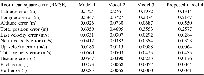
To validate the performance of the proposed stochastic model in GNSS/INS integration, the navigation accuracies with various stochastic models are compared and analysed statistically as follows. It can be seen from Figures 12–14 that the position, velocity and attitude errors of the proposed model 4 are much more stable and lower than the three other models, and meanwhile, its improvement is more evident where there is no obvious correlation between the navigation error and the manoeuvre trajectory. As seen in Table 4, the proposed model 4 produces an RMS position error of 0.2577 m, an RMS velocity error of 0.0435 m/s, an RMS heading error of 0.0176°, an RMS pitch error of 0.0044° and an RMS roll error of 0.0041°. Compared with the other three models, the proposed model 4 shows outstanding performance in GNSS/INS integration, where the percentage improvement in position, velocity, heading, pitch and roll accuracy was enhanced by 62.97% (45.11%, 27.47%), 22.32% (13.52%, 8.42%), 67.82% (54.87%, 24.46%), 39.73% (35.29%, 15.38%), and 51.76% (36.92%, 31.67%) against model 1 (model 2, model 3).
Position errors comparison of models 1, 2, 3 and 4.

Velocity errors comparison of models 1, 2, 3 and 4.

Figure 13. Long description
Three line graphs compare velocity errors of four models over time. Panel A: The line graph shows East Velocity Error in meters per second (m/s) over time in milliseconds (ms). The x-axis ranges from 5.37 to 5.41 times 10^8 ms, and the y-axis ranges from -0.2 to 0.2 m/s. Four models are represented by different colors: red for model 1, blue for model 2, green for model 3, and purple for model 4. Panel B: The line graph shows North Velocity Error in meters per second (m/s) over time in milliseconds (ms). The x-axis ranges from 5.37 to 5.41 times 10^8 ms, and the y-axis ranges from -0.2 to 0.2 m/s. Four models are represented by different colors: red for model 1, blue for model 2, green for model 3, and purple for model 4. Panel C: The line graph shows Up Velocity Error in meters per second (m/s) over time in milliseconds (ms). The x-axis ranges from 5.37 to 5.41 times 10^8 ms, and the y-axis ranges from -0.15 to 0.15 m/s. Four models are represented by different colors: red for model 1, blue for model 2, green for model 3, and purple for model 4.
Attitude errors comparison of models 1, 2, 3 and 4.

Navigation accuracies of GNSS/INS with various stochastic models.

Table 4. Long description
A table comparing the root mean square error (RMSE) of different models in GNSS/INS integration. The table has 12 rows and 5 columns. The columns are labeled as Model 1, Model 2, Model 3, and Proposed model 4. The rows are labeled as Latitude error (m), Longitude error (m), Altitude error (m), Total position error (m), East velocity error (m/s), North velocity error (m/s), Up velocity error (m/s), Total velocity error (m/s), Heading error (°), Pitch error (°), and Roll error (°). Row 1: Latitude error (m), Model 1: 0.5724, Model 2: 0.2761, Model 3: 0.1972, Proposed model 4: 0.1314. Row 2: Longitude error (m), Model 1: 0.3847, Model 2: 0.3727, Model 3: 0.2874, Proposed model 4: 0.2147. Row 3: Altitude error (m), Model 1: 0.0926, Model 2: 0.0730, Model 3: 0.0687, Proposed model 4: 0.0550. Row 4: Total position error (m), Model 1: 0.6959, Model 2: 0.4695, Model 3: 0.3553, Proposed model 4: 0.2577. Row 5: East velocity error (m/s), Model 1: 0.0331, Model 2: 0.0307, Model 3: 0.0292, Proposed model 4: 0.0284. Row 6: North velocity error (m/s), Model 1: 0.0412, Model 2: 0.0382, Model 3: 0.0364, Proposed model 4: 0.0323. Row 7: Up velocity error (m/s), Model 1: 0.0185, Model 2: 0.0115, Model 3: 0.0088, Proposed model 4: 0.0064. Row 8: Total velocity error (m/s), Model 1: 0.0560, Model 2: 0.0503, Model 3: 0.0475, Proposed model 4: 0.0435. Row 9: Heading error (°), Model 1: 0.0547, Model 2: 0.0390, Model 3: 0.0233, Proposed model 4: 0.0176. Row 10: Pitch error (°), Model 1: 0.0073, Model 2: 0.0068, Model 3: 0.0052, Proposed model 4: 0.0044. Row 11: Roll error (°), Model 1: 0.0085, Model 2: 0.0065, Model 3: 0.0060, Proposed model 4: 0.0041.
Further, to evaluate the real-time performance and computational complexity of the proposed estimation scheme, the elapsed time and memory requirement are compared between the conventional computation approach and the proposed computation approach (see Table 1). The memory requirement is calculated by summing the memory sizes of all the temporary variables necessary for a complete iteration of the Kalman filter. The elapsed time is obtained by measuring the time duration of one Kalman filter iteration (see Equation (22)). The profiling approach has been considered to measure the elapsed time by MATLAB on a test machine with Intel Core i5-4200 CPU at 2.60 GHz and 4 GB of RAM. As seen in Table 5, the conventional computation approach entails a computational burden and requires a considerable memory size for model 4 (42-dimension), due to high-dimension matrix multiplication with the dot-product method. Meanwhile, the computational complexity can be significantly reduced by using the proposed computation approach, where the processing speed is increased by more than 41.18% and the memory requirement is decreased by approximately 14.08%.
Comparison of computational complexity.

Table 5. Long description
A table comparing computational complexity between conventional and proposed approaches. The table has two columns: Conventional approach and Proposed approach. It has two rows: Elapsed time (ms) and Memory requirement (KB). Row 1: Conventional approach, 0.051; Proposed approach, 0.030. Row 2: Conventional approach, 24.468; Proposed approach, 21.023.
5. Conclusion
In this paper, multiple INS crucial errors are discussed and modelled according to the remote sensing survey requirement, and a more accurate high-dimensional (42 states) system error model of the GNSS/INS Kalman filter is established that comprehensively considers the influence of inertial sensor errors and approximate processing errors. Then, a real-time estimation scheme with a high-efficiency Kalman filter is proposed for the 42-dimensional system error model, which avoids heavy computational burden as well as retaining optimality. It was demonstrated through flight experiments that the proposed 42-dimensional model offers better estimation and navigation precision than the other models. Finally, compared with the conventional matrix product approach, experiment results show that the proposed estimation scheme has nearly 41.18% and 14.08% performance improvements on the processing speed and the memory requirement.
Nevertheless, this study has some limitations. First, the accelerometer and gyro biases are modelled as the sum of a constant and a Markov state, which is only a rough approximation of the sensor behaviour. Second, the gravity disturbance is modelled as an exponentially correlated fixed-variance first-order Markov process, which performs well in flat terrain regions but yields significant errors over mountain ranges and ocean trenches. To address the above limitations, future work can be pursued as along the following directions:
-
(1) representing the accelerometer and gyro biases as second- and third-order autoregressive models with tuning to each sensor type;
-
(2) using a precision gravity model (such as the 4,730,400-coefficient EGM 2008 gravity model), or a gravity gradiometer to measure gravitational variations in real time.
Overall, the proposed high-dimensional system error model and real-time estimation scheme presented in this paper are of great significance for improving the navigation accuracy of the GNSS/INS integrated system. The aforementioned limitations do not compromise the validity of the main conclusions, but instead highlight key directions for further improvement.
Funding statement
The authors disclosed receipt of the following financial support for the research, authorship and/or publication of this paper. This work was financially supported in part by the National Natural Science Foundation of China under Grant 61763005, Guizhou Provincial Key Technology R&D Program under Grant [2026]025 and XKBF [2025]032, and Guizhou Provincial Major Scientific and Technological Program under Grant XKBF[2025]031.
Competing interests
The authors declare that they have no conflict of interest.