

1. INTRODUCTION
The Inertial Navigation System (INS) is essentially a dead reckoning system. Hence, the initial condition, which is determined by the initial alignment, should be provided prior to navigation computation. Generally, the initial alignment for a high-precision INS can be achieved directly based on the output of gyros and accelerometers, known as self-alignment. For the low-cost INS, the noise threshold of gyros is near or higher than the Earth's rotation rate
 $({\approx}15^{\circ} / \hbox{h})$
, which means it cannot detect the Earth's rotation rate properly (Han and Wang, Reference Han and Wang2010). In this respect, the initial alignment approach for high-end INS is not feasible for low-cost INS. A popular approach is to use an external aiding sensor to provide additional information as reference for alignment.
With the vehicle held stationary, low cost systems initialise the pitch and roll angles using an accelerometer-measured gravitational field vector (Burak and Bekir, Reference Burak and Bekir2015). Heading is obtained externally using a magnetometer (Li and Wang, Reference Li and Wang2013). For systems integrated with the Global Positioning System (GPS), the velocity supplied by GPS provides a heading after the vehicle has started to move (Dissanayake et al., Reference Dissanayake, Sukkarieh, Nebot and Durrant-Whyte2001). Unfortunately, the former method can only work effectively without dynamic accelerations and the measurements of magnetometers suffer from local magnetic interference. The latter method requires the vehicle to move at a strictly constant speed. In addition to this, the installation situation of INS relative to the vehicle should be determined prior to heading alignment.
The last decade has shown an increasing demand for small-sized and low-cost inertial navigation systems in many applications. However, initial alignment is still a challenging issue for these domains. It is especially difficult to estimate the attitude when the vehicle is moving. For example, smart munitions and guided missiles with a GPS-aided navigation system can be launched at any given time. The alignment must be done in-flight based on GPS information.
Various in-motion alignment techniques have been reported. Joon et al. (Reference Joon, Jang and Chan2004) suggested an in-flight alignment for a Strapdown Inertial Navigation System/Global Positioning System (SINS/GPS) using carrier phase rate measurement. The proposed method is more efficient than the velocity-aided one, which, nevertheless, requires two GPS antennae. Han and Wang (Reference Han and Wang2010) introduced a two-stage Kalman filtering mechanism for the initial alignment of low-cost INS aided by GPS. The first stage is designed for the coarse alignment, and the second is for the fine alignment. Obviously, the alignment process must switch from a coarse alignment filter to a fine alignment filter. However, the error dynamic is just suitable for small attitude errors. To deal with large initial attitude error, some works provided nonlinear filtering methods (Scherzinger, Reference Scherzinger1996; Kong et al., Reference Kong, Nebot and Durrant-Whyte1999; Bimal and Ashok, Reference Bimal and Ashok2015; Yuan et al., Reference Yuan, Ma, Liu and Zhang2016). Kong et al. (Reference Kong, Nebot and Durrant-Whyte1999) developed a non-linear error dynamics model for all three large misalignment angles. The benefit of this method is that the coarse alignment stage is eliminated. However, this model suffers from complex non-linear operations. Li et al. (Reference Li, Wang, Lu and Wu2013) proposed a scheme for a Doppler Velocity Log (DVL)-aided Strapdown Inertial Navigation System (SINS) in-motion alignment using the Unscented Kalman Filter (UKF), which can deal with any initial heading errors. Bimal and Ashok (Reference Bimal and Ashok2015) developed a nonlinear wander azimuth error model that can be used for DVL-aided in-motion alignment and compared the performance of a UKF and an Extended Kalman Filter (EKF). This study did not consider sensor biases. The drawbacks of the above methods, however, are well-known linearization effects and computational load.
Recently, the Optimisation-Based initial Alignment (OBA) method has been developed (Gu et al., Reference Gu, EI-Sheimy and Hassan2008; Silson, Reference Silson2011; Wu et al., Reference Wu, Wu, Hu and Hu2011; Kang et al., Reference Kang, Fang and Wang2012; Li et al., Reference Li, Xu, Chang and Feng2014; Lu et al., Reference Lu, Xie and Li2016). The essence of the OBA method is to determine the constant attitude matrix at start-up of the initial alignment using infinite vector observations. Wu and Pan (Reference Wu and Pan2013) proposed an optimisation-based in-flight coarse alignment approach based on velocity/position integration. Flight tests of a navigation-grade SINS were used to evaluate the two alignment algorithms. However, they did not take the sensor bias into account and no test was done on low-cost SINS. Similar to Wu and Pan's method, Chang et al. (Reference Chang, Li and Chen2015) extended the idea of the OBA method and gave a filtering called Modified Unscented Quaternion Estimator (MUSQUE) which can estimate the gyroscope biases other than the attitude quaternion.
In the present work, a Rodrigues parameters-based optimal estimator is proposed as a synthesis of the approaches mentioned above. Like the quaternion-based estimator, the proposed estimator consists of two stages. The first stage features an optimal estimation of a constant Rodrigues parameters vector. Then, the second stage produces a constant attitude matrix from the filtered Rodrigues parameters vector via the Cayley transform. Our contribution resides in the following properties:
-
• An ordinary linear Kalman Filter (KF) is applied on the state-space model. The measurement equation is quadratic with respect to the Rodrigues parameters vector. This equation is linearized by employing a Taylor expansion and the linearized model is implemented in a second order Extended Kalman Filter (EKF2), thus reducing the linearization effects of the EKF and avoiding the computational load of the nonlinear filter method.
-
• The initial alignment process does not need to be divided into two stages. A single Kalman Filter can complete the initial alignment under random misalignment angles.
-
• The proposed method circumvents one drawback of previous alignment methods, which is the difficulty of estimating parameters other than the attitude, such as the gyroscope and accelerometer biases. This is a desirable property for MEMS-based low-cost SINS.
The remainder of this paper is organised as follows. In Section 2, we review the conventional initial alignment scheme for low-cost SINS aided by GPS. In Section 3, based on Rodrigues parameters, the alignment dynamic model under random misalignment angles is established. Furthermore, employing exact Taylor series expansions, second-order EKF update equations are derived. Experimental tests on a vehicle with a low-cost MEMS Inertial Measurement Unit (IMU) are presented in Section 4. The data from dynamic experiments is processed by the proposed method and conventional in-motion initial alignment method for comparison. The conclusions of the present work are presented in the last section.
2. CONVENTIONAL INITIAL ALIGNMENT SCHEME FOR LOW-COST SINS AIDED BY GPS
The traditional initial alignment scheme aided by GPS is divided into two stages, namely, the coarse alignment stage and the fine alignment stage. The coarse alignment can be achieved through the classical least-squares approach generally introduced in 1965, the so-called Wahba's problem (Choukronun et al., Reference Choukronun, Bar-Itzhack and Oshman2004), which is a constrained least-squares estimation problem for finding the attitude matrix.
The fine alignment can be performed by a basic Kalman filter based on the INS linear error models of small attitude errors (Li et al., Reference Li, Pan, Wang, Jiang and Wang2015; Han and Wang, Reference Han and Wang2010). Velocity and position information from the GPS with manoeuvring is employed as a measurement to estimate the residual attitude errors coming from the coarse alignment stage.
2.1. Coarse Alignment in the Inertial Coordinate Frame
It is easy to show that the apparent gravity expressed within the inertial space defines a cone whose main axis is the rotational axis of the earth, by using vector observations of the projective gravity vector to accomplish the initial Attitude Determination (AD), which transforms the attitude alignment into a constant attitude estimation problem.
The attitude matrix can be decomposed into three parts based on the chain rule as follows:
 $${\bi C}_{b}^{n}(t) = {\bi C}_{i_n}^{n}(t) {\bi C}_{i_b}^{i_n} {\bi C}_{b}^{i_b}(t)$$
where n and b are the local-level geographic frame and the body frame. i n and i b denote the auxiliary inertial frame, which are aligned with n and b at start-up of the alignment and are inertially “frozen” thereafter, respectively.
Equation (1) shows that the attitude matrix
 ${\bi C}^{n}_{b}(t)$
is composed of three parts:
(a)
 ${\bi C}^{i_{b}}_{b}(t)$
represents the time-varying attitude due to the rotation of the b-frame relative to the inertial frame i
b
as a function of inertial angular rate which is measured by gyros
 $$\dot {\bi C}_{b}^{i_b}(t) ={\bi C}_{b}^{i_b}(t) ({\bf \omega}_{i_b}^{b} \times), \quad {\bi C}_{b}^{i_b}(t) = {\bi I}$$
using the two-sample coning correction algorithm (Savage, Reference Savage1998; Qin, Reference Qin2014).
The updating algorithm can be constructed as follows using the product chain rule:
 $${\bi C}_{b}^{i_b}(t_{k}) ={\bi C}_{b}^{i_b} (t_{k-1}) {\bi C}_{b (t_k)}^{b (t_{k-1})}$$
(b)
 ${\bi C}_{i_{n}}^{n}(t)$
describes the time-varying attitude due to the earth rotation rate and the vehicle's transport rate relative to the Earth. The analytic expression is
 $${\bi C}_{i_n}^{n} (t) = \left[ \matrix{ \cos \delta \lambda \cr \cr -\sin L_k \sin \delta \lambda \cr \cr \cos L_k \sin \delta \lambda} \quad \matrix{\sin L_0 \sin \delta \lambda \cr \left(\eqalign{ \sin L_0 \sin L_k \cos \delta \lambda \cr + \cos L_0 \cos L_k \quad} \right) \cr \left(\eqalign{ -\sin L_0 \cos L_k \cos \delta \lambda \cr + \sin L_k \cos L_0 \quad} \right)} \quad \matrix{- \cos L_0 \sin \delta \lambda \cr \left(\eqalign{ -\sin L_k \cos L_0 \cos \delta \lambda \cr + \cos L_k \sin L_0 \quad} \right) \cr \left(\eqalign{ \cos L_0 \cos L_k \cos \delta \lambda \cr + \sin L_k \sin L_0 \quad} \right)} \right]$$
where L
0 and λ0 are the latitude and longitude at the start time of the alignment process; L
k
and λ
k
are the latitude and longitude at time t
k
(output of GPS);
 $\delta \lambda = \lambda_{k}-\lambda_{0}+\omega_{ie}t$
.
(c) The core part
 ${\bi C}^{i_{n}}_{i_{b}}$
is a constant matrix, which represents the relationship between inertial frames i
b
and i
n
. According to Gu et al. (Reference Gu, EI-Sheimy and Hassan2008) and Wu and Pan (Reference Wu and Pan2013),
 ${\bi C}^{i_{n}}_{i_{b}}$
can be derived by solving the attitude determination problem using infinite vector observations as
 $${\bi V}^{i_n} = {\bi C}_{i_b}^{i_n} {\bi V}^{i_b}$$
where
 $$\eqalign{ {\bi V}^{i_b} =& \int_0^t {\bi C}^{i_{b}}_{b} (t) {\bi f}^{b} (t) dt \cr {\bi V}^{i_n} =& \int_0^t {\bi C}^{i_{n}}_{n} (t) \left[ \dot{\bi v}^n + (2 {\bi \omega}_{ie}^{n} + {\bi \omega}_{en}^{n}) \times {\bi v}^{n} -{\bi g}^n \right] {\bi f}^b (t) dt}$$
Equation (5) is known as the classic Wahba's problem using two or more vector pair observations, and various authors (Choukronun et al., Reference Choukronun, Bar-Itzhack and Oshman2004) have presented solutions to this least squares optimisation problem. If the initial attitude matrix
 ${\bi C}^{i_{n}}_{i_{b}}$
is known, the continuous time
 ${\bi C}^{n}_{b}(t)$
can be obtained by Equation (1).
2.2. Fine Alignment based on Kalman Filter
The coarse alignment discussed in Section 2.1 will make the misalignment converge to a small angle. Under the condition of small platform misalignment, the fine alignment can proceed.
The state vector of the KF in the fine alignment process is generally selected as
 $${\bi X} = \left[ ({\bi \varphi}^n)^{\rm T} \quad (\delta {\bi v}^n)^{\rm T} \quad (\delta {\bi p}^n)^{\rm T} \quad ({\bi \varepsilon}^b)^{\rm T} \quad {\bi \nabla}^b)^{\rm T} \right]^{\rm T}$$
where
 ${\bi \varphi}^{n}$
denotes the misalignment angle,
 $\delta {\bi v}^{n}$
is the velocity error vector, and
 $\delta {\bi p}^{n}$
is the position error vector.
 ${\bi \varepsilon}^{b}$
and
 ${\bi \nabla}^{b}$
denote the gyro and accelerometer biases, respectively.
Using navigation-frame GPS velocity and position aiding, the measurements used in the Kalman filter are the velocity and position differences between INS and GPS. Hence the measurement model is given below:
 $${\bi Z} = \left[\matrix{ {\bi v}_{INS}^{n} - {\bi v}_{GPS}^{n} \cr {\bi p}_{INS}^{n} - {\bi p}_{GPS}^{n} } \right] = {\bi HX} + {\bi V}$$
where
 ${\bi H} = \left[ {\bi 0}_{6\times 3} \quad {\bi I}_{6\times 6} \quad {\bi 0}_{6\times 6} \right]$
.
3. IN-MOTION ALIGNMENT FOR LOW-COST SINS/GPS AIDED BY GPS
3.1. Alignment Dynamic Model under Random Misalignment Angles
Equation (5) cannot be satisfied by all the measurements, due to sensor noise. In particular, we assume that the integration of the accelerometer-measured specific force at time t k in the inertial frame i b is given by following expression:
 $$\hat{\bi V}^{i_b} (t_k) = {\bi V}^{i_b} (t_k) + \delta {\bi V}^{i_b} (t_k)$$
where
 $\delta {\bi V}^{i_{b}}(t_{k})$
is the integration error of
 ${\bi V}^{i_{b}} (t_{k})$
.
Then Equation (5) can be rewritten as
 $${\bi V}^{i_n} (t_k) = {\bi C}_{i_b}^{i_n} \left ( \hat{\bi V}^{i_b} (t_k) - \delta {\bi V}^{i_b} (t_k)\right) $$
Our method is developed from the relationship equivalent to Equation (5), but written in terms of the Rodrigues vector. This is obtained by mapping the attitude matrix to a minimum-element attitude parameterisation expressed by the skew-symmetric Rodrigues matrix, using the Cayley transform (Daniele et al., Reference Daniele, Markley and Puneer2007; Junkins and Kim, Reference Junkins and Kim1993). The relationship of attitude matrix
 ${\bi C}^{i_{b}}_{i_{n}}$
and the Rodrigues matrix is
 $${\bi C}_{i_n}^{i_b} = \lsqb {\bi I} + {\bi l} (\times)\rsqb ^{-1} \lsqb {\bi I} - {\bi l} (\times)\rsqb $$
where
 ${\bi l} (\times)$
is a skew-symmetric matrix related to the elements of the Rodrigues vector
 ${\bi l}$
.
Substituting Equation (10) into Equation (9) and reorganising the equation yields
 $$\hat{\bi V}^{i_b} (t_k) = {\bi V}^{i_n} (t_k) = (\hat{\bi V}^{i_b} (t_k) + {\bi V}^{i_n} (t_k)) \times {\bi l} + {\bi l} \times \delta {\bi V}^{i_b} (t_k) + \delta {\bi V}^{i_b} (t_k) + {\bi w}_{t_k}$$
where
 ${\bi w}_{t_{k}}$
is the integration of the inertial sensor error.
Defining the sum and difference as follows:
 $${\bi S}_{t_k} = \hat{\bi V}^{i_b} (t_k) + {\bi V}^{i_n} (t_k),\quad {\bi D}_{t_k} = \hat{\bi V}^{i_b} (t_k) - {\bi V}^{i_n} (t_k)$$
Substituting Equation (12) into Equation (11), we obtain
 $${\bi D}_{t_k} = {\bi S}_{t_k} \times {\bi l} + {\bi l} \times \delta {\bi V}^{i_b} (t_k) + \delta {\bi V}^{i_b} (t_k) + {\bi w}_{t_k}$$
Equation (13) is the measurement equation of Rodrigues parameters vector
 ${\bi l}$
, which is equivalent to constant attitude matrix
 ${\bi C}_{i_{n}}^{i_{b}}$
. If the optimal estimate of Rodrigues parameters vector
 ${\bi l}$
is known,
 ${\bi C}_{i_{n}}^{i_{b}}$
can be obtained by Equation (10).
In Equation (2), we substitute
 ${\bi C}_{b}^{i_{b}}$
,
 ${\bi \omega}_{i_{b}}^{b}$
by
 $\hat{\bi C}_{b}^{i_{b}}$
and
 $\hat{\bi \omega}_{i_{b}}^{b}$
, respectively. The time subscripts are omitted for the sake of clarity, that is
 $$\dot{\hat{\bi C}}_{b}^{i_b} = \hat{\bi C}_{b}^{i_b} (\hat{\bi \omega}_{i_b}^{b} \times)$$
assuming that the error of
 $\hat{\bi C}_{b}^{i_{b}}$
just introduced by gyro bias of SINS, and the computing platform misalignment angles
 $\varphi^{i_{b}}$
is small in alignment process. Then we obtain
 $$\hat{\bi C}_{b}^{i_b} (t) = \lsqb {\bi I}_{3} - ({\bi \varphi}^{i_b} \times) \rsqb {\bi C}_{b}^{i_b}$$
 $$\hat{\bi \omega}_{i_b}^{b} = {\bi \omega}_{i_b}^{b} + {\bi \varepsilon}^{b} + {\bi w}_{g}^{b}$$
where
 ${\bi \varepsilon}^{b}$
,
 ${\bi w}_{g}^{b}$
are gyro biases and the noise of SINS, respectively.
Now if we can differentiate both sides of Equation (15) and substitute Equations (2), (14) and (16) then we obtain the following differential equation
 $$\dot{\bi \varphi}^{i_b} = -\hat{\bi C}_{b}^{i_b} ({\bi \varepsilon}^{b} + {\bi w}_{g}^{b}), {\bi \varphi}^{i_b} (0) = 0$$
From Equations (5) and (8) we can see that
 $$\hat{\bi V}^{i_b} = {\bi V}^{i_b} + \delta {\bi V}^{i_b} = \int_0^t \hat{\bi C}_{b}^{i_b} \hat{\bi f}^{b} dt$$
 $$\hat{\bi f}^{b} = {\bi f}^{b} + \nabla^b +{\bi w}_{a}^{b}$$
where
 $\nabla^{b}, {\bi w}_{a}^{b}$
are accelerometer biases and the noise of SINS, respectively.
Substituting Equations (15) and (19) into Equation (18), and discarding the higher order slim terms, we have
 $$\delta \dot{\bi V}^{i_b} = \hat{\bi f}^{i_b} \times {\bi \varphi}^{i_b} + \hat{\bi C}_b^{i_b} (\nabla^b + {\bi w}_{a}^{b}), \delta {\bi V}^{i_b} (0) = 0$$
As the matrix
 ${\bi C}_{i_{n}}^{i_{b}}$
can be considered as a constant attitude matrix during the alignment process, the correlated Rodrigues parameters vector in Equation (10) satisfies the following differential equation
 $${\bi l} = {\bi 0}$$
Equations (17), (20), and (21) constitute the dynamic model. Taking the gyroscope drifts
 ${\bi \varepsilon}^{b}$
and accelerometer biases ∇
b
into account as constant, the complete state vector is selected as follows
 $${\bi X} = \left[ {\bi l}^{\rm T} \quad \left ( {\bi \varphi}^{i_b} \right)^{\rm T} \quad \left ( \delta {\bi V}^{i_b} \right)^{\rm T} \quad \left ( {\bi \varepsilon}^{b} \right)^{\rm T} \quad \left ( {\bi \nabla}^{b} \right)^{\rm T} \right]^{\rm T}$$
The alignment dynamic model under random misalignment angles can therefore be written as
 $$\left[\matrix{ \dot{\bi l} \cr \dot{\bi \varphi}^{i_b} \cr \delta \dot{\bi V}^{i_b} \cr \dot{\bi \varepsilon}^{b} \cr \dot{\bi \nabla}^{b} } \right] = \left[\matrix{ {\bi 0}_{3\times3} \quad {\bi 0}_{3\times3} \quad {\bi 0}_{3\times3} \quad {\bi 0}_{3\times3} \quad {\bi 0}_{3\times3} \cr {\bi 0}_{3\times3} \quad {\bi 0}_{3\times3} \quad {\bi 0}_{3\times3} \quad -\hat{\bi C}_{b}^{i_b} \quad {\bi 0}_{3\times3} \cr {\bi 0}_{3\times3} \quad \hat{\bi f}^{i_b}\times \quad {\bi 0}_{3\times3} \quad {\bi 0}_{3\times3} \quad \hat{\bi C}_{b}^{i_b} \cr {\bi 0}_{3\times3} \quad {\bi 0}_{3\times3} \quad {\bi 0}_{3\times3} \quad {\bi 0}_{3\times3} \quad {\bi 0}_{3\times3} \cr {\bi 0}_{3\times3} \quad {\bi 0}_{3\times3} \quad {\bi 0}_{3\times3} \quad {\bi 0}_{3\times3} \quad {\bi 0}_{3\times3} } \right] \left[ \matrix{ \dot{\bi l} \cr \dot{\bi \varphi}^{i_b} \cr \delta {\bi V}^{i_b} \cr {\bi \varepsilon}^{b} \cr {\bi \nabla}^{b} }\right] + \left[\matrix{ {\bi 0}_{3 \times 1} \cr -\hat{\bi C}_{b}^{i_b} {\bi w}_{g} \cr \hat{\bi C}_{b}^{i_b} {\bi w}_{a} \cr {\bi 0}_{3\times1} \cr {\bi 0}_{3\times1} } \right]$$
Equation (13) can be rewritten as
 $${\bi Z}_k = {\bi D}_k = {\bi h} ({\bi X}_k) + {\bi w}_k = {\bi S}_k \times {\bi l} + ({\bi I} + {\bi l} \times) \delta {\bi V}^{i_b} + {\bi w}_k$$
Note that the measurement Equation (24) is derived without any assumption for misalignment, which means that the alignment dynamic model can be established in the same form whether the misalignment angle is small or not. In this respect, a unified in-motion alignment model under random misalignment angles is proposed based on integration of the specific force.
3.2. Second-order Nonlinear Measurement Filter Algorithm based on Second-order Extended Kalman Filter
The state process Equation (23) is linear. In contrast, the measurement Equation (24) is quadratic nonlinear. Measurement Equation (24) is linearized accurately by applying a Taylor series expansion around
 ${\bi X}_{k0}$
to second-order terms as
 $${\bi h}({\bi X}_k)={\bi h}({\bi X}_{k0}) + {\bi H}_k {\bi X}_k + {1\over 2} \sum\limits_{i=1}^{3} {\bi e}_i \hbox{Tr} ({\bi D}_i \tilde{\bi X}_k \tilde{\bi X}_k^{\rm T})$$
where
 ${\bi X}_{k0}$
is the current best estimate of
 ${\bi X}_{k}$
,
 $\tilde{\bi X}_{k} = {\bi X}_{k} - {\bi X}_{k0}$
,
 ${\bi e}_{i}$
is a 3×1 unit vector with 1 in the element i and 0 elsewhere,
 ${\bi H}_{k}$
denotes the Jacobian matrix of the nonlinear function
 ${\bi h}$
,
 ${\bi D}_{i}$
denotes the Hessian matrix of the nonlinear function
 ${\bi h}$
, and “Tr” denotes the trace operator.
Note that the second partial derivative matrix of nonlinear function is a constant matrix. That is, the element of matrix
 ${\bi D}_{i}$
is scalar. From Equations (23) and (24), nonzero scalars of
 ${\bi D}_{i}$
are as follows:
 $$\matrix{ {\bi D}_1 (2,9) = 1, \hfill \cr {\bi D}_1 (3,8) = -1, \hfill \cr {\bi D}_1 (9,2) = 1, \hfill \cr {\bi D}_1 (8,3) = -1,} \quad \matrix{ {\bi D}_2 (1,9) = -1 \hfill \cr {\bi D}_2 (3,7) = 1, \hfill \cr {\bi D}_2 (9,1) = -1, \hfill \cr {\bi D}_2 (7,3) = 1,\hfill } \quad \matrix{ {\bi D}_3 (1,8) = 1, \hfill \cr {\bi D}_3 (2,7) = -1, \hfill \cr {\bi D}_3 (8,1) = 1, \hfill \cr {\bi D}_3 (7,2) = -1,}$$
The remaining elements in matrix
 ${\bi D}_{i}$
are zeros.
Equation (23) is clearly a linear state equation. This means we can use the standard KF equations to estimate the state.
Now we will derive the measurement update equations based on Equation (25) in the form of a second-order Taylor series expansion. Suppose that the state estimate at
 ${\bi t}_{k}$
is given as
 $$\hat{\bi X}_{k} = \hat{\bi X}_{k/k-1} + {\bi K}_k \left[ {\bi Z}_k - {\bi h} (\hat{\bi X}_{k/k-1}) - {\bi L}_k \right] $$
where
 ${\bi L}_{k}$
is a correction term to assure the estimate
 $\hat{\bi X}_{k}$
is unbiased, and we will then choose
 ${\bi K}_{k}$
to minimise the trace of the covariance of the estimate.
Define the estimate errors as
 $$\tilde{\bi X}_k = {\bi X}_k - \hat{\bi X}_k = \hat{\bi X}_{k/k-1} - (\hat{\bi X}_{k} - \hat{\bi X}_{k-1})$$
where
 $\tilde{\bi X}_{k/k-1} = {\bi X}_{k} - \hat{\bi X}_{k/k-1}$
From Equations (25), (27) and (28), we have
 $$\tilde{\bi X}_{k} = \tilde{\bi X}_{k/k-1} - {\bi K}_k {\bi H}_k \tilde{\bi X}_{k/k-1} - {\bi K}_k {\bi w}_k - {\bi K}_k \left[{1\over 2} \sum\limits_{i=1}^{3} {\bi e}_i \hbox{Tr} ({\bi D}_i \tilde{\bi X}_{k/k-1} \tilde{\bi X}_{k/k-1}^{\rm T}) -{\bi L}_k \right]$$
Assuming that time-update
 $\hat{\bi X}_{k/k-1}$
is unbiased, taking the expected value of both sides of Equation (29) and making the result zeros, we obtain
 $${\bi L}_k = E \left[{1\over 2} \sum\limits_{i=1}^{3} {\bi e}_i \hbox{Tr} ({\bi D}_i \tilde{\bi X}_{k/k-1} \tilde{\bi X}_{k/k-1}^{\rm T}) \right] = {1\over 2} \sum\limits_{i=1}^{3} {\bi e}_i \hbox{Tr} ({\bi D}_i {\bi P}_{k/k-1})$$
Substituting Equation (30) into Equation (29) we have
 $$\tilde{\bi X}_{k} = ({\bi I} - {\bi K}_k {\bi H}_k) \tilde{\bi X}_{k/k-1} + {\bi K}_k {\bi A} - {\bi K}_k {\bi w}_k$$
where
 $${\bi A} = {1\over 2} \sum\limits_{i=1}^{3} {\bi e}_i \hbox{Tr} \left[ ({\bi D}_i {\bi P}_{k/k-1})({\bi D}_j {\bi P}_{k/k-1}) \right]$$
Since
 $E (\tilde{\bi X}_{k}) = 0, E ({\bi w}_{k}) = 0$
,
 ${\bi w}_{k}$
and
 ${\bi A}$
are uncorrelated, we can see from Equations (31) and (32) that
 $${\bi P}_k = E\left[ \tilde{\bi X}_{k} \tilde{\bi X}_{k}^{\rm T} \right] = ({\bi I} - {\bi K}_k {\bi H}_k) {\bi P}_{k/k-1} ({\bi I} - {\bi K}_k {\bi H}_k)^{\rm T} + {\bi K}_k ({\bi R}_k + \Lambda_k) {\bi K}^{\rm T}$$
where
 $$\Lambda_k =E \left[ {\bi AA}^{\rm T} \right]$$
The second-order EKF can be summarised in the following. Additional derivations can be found in Simon (Reference Simon2006) or Qin et al. (Reference Qin, Zang and Wang2014).
-
a) Time-update equations:
(35) $$\hat{\bi X}_{k/k-1} = {\bi \Phi}_{k/k-1} \hat{\bi X}_{k-1}$$
(36)
$${\bi P}_{k/k-1} = {\bi \Phi}_{k/k-1} {\bi P}_{k-1} {\bi \Phi}_{k/k-1}^{\rm T} + {\bi Q}_{k}$$
-
b) Measurement update equations:
(37)
$$\hat{\bi X}_{k} = \hat{\bi X}_{k/k-1} + {\bi K}_k \left[ {\bi Z}_k - {\bi h} (\hat{\bi X}_{k/k-1}) - {\bi L}_k \right]$$
(38)
$${\bi K}_k = {\bi P}_{k/k-1} {\bi H}_{k}^{\rm T} ({\bi H}_k {\bi P}_{k/k-1} {\bi H}_{k}^{\rm T} + {\bi R}_{k} + \Lambda_k)^{-1}$$
(39)
$$\Lambda_k (i, j) = {1\over 2}\hbox{Tr} \left[ ({\bi D}_{i} {\bi P}_{k/k-1}) ({\bi D}_{j} {\bi P}_{k/k-1}) \right]$$
(40)
$${\bi P}_{k} = ({\bi I} - {\bi K}_{k} {\bi H}_k) {\bi P}_{k/k-1} ({\bi I} - {\bi K}_k {\bi H}_k)^{\rm T} + {\bi K}_k ({\bi R}_k + \Lambda_k) {\bi K}^{\rm T}$$


From Measurement update Equations (35)~(40), we know that the second-order EKF equations are similar to the conventional linear KF, just with two additional terms,
 ${\bi L}_{k}$
and Λ
k
.
3.3. Scheme for Avoiding Singularity
The well-known Rodrigues parameters algorithm suffers from a singularity in the case of a π-rotation between the coordinate frames, i
b
and i
n
, because the norm of the Gibbs vector becomes unbounded for such a rotation (Qin et al., Reference Qin, Zang and Wang2014; Mei et al., Reference Mei, Qin and Yang2015). This problem can be eliminated completely by employing the method of sequential rotations, as introduced in Shuster and Oh (Reference Shuster and Oh1980). We apply a certain virtual rotation from the frame i
b
to a new coordinate frame
 $i_{b^{\prime}}$
, and make the Rodrigues parameters that represent the orientation of
 $i_{b^{\prime}}$
and i
n
away from the singular position. By so doing, the estimation of
 ${\bi l}_{i_{n}}^{i_{b}}$
can also be obtained indirectly from the result
 ${\bi l}_{i_{n}}^{i_{b^{\prime}}}$
, which is the basic idea of designing the scheme for avoiding singularity.
However, in practice, it is possible to know in advance which rotation is not needed due to the principal axis being far from its singular position (Daniele et al., Reference Daniele, Markley and Puneer2007). For example, in the Rodrigues parameters algorithm singularity for land vehicles or airborne vehicles, which occurs only when the attitude angles are small, the yaw angle is close to π (Mei et al., Reference Mei, Qin and Yang2015). Then, the singularity avoiding method of GPS-aiding is summarised below.
Step 1: At the start-up of the alignment, the estimate of yaw angle and pitch angle are available by using only the GPS velocity measurement vector
 $\hat{\bi v}_{0}^{n}$
 $$\displaystyle\left\{ \matrix { \hat{\psi} = \hbox{arctan} 2 (\hat{\bi v}_{0E}^{n}, \hat{\bi v}_{0N}^{n}) \hfill \cr \hat{\theta} = \hbox{arctan} 2 \displaystyle\left ( \hat{\bi v}_{0U}^{n}, \sqrt {( \hat{\bi v}_{0E}^{n} )^2 + ( \hat{\bi v}_{0N}^{n} )^2} \right )} \right.$$
where arctan 2 is the four-quadrant tangent inverse,
 $\hat{\bi v}_{0i}^{n} (i = E, N, U)$
are the GPS velocity measurement components in the East, North and vertical direction, respectively.
Step 2: Compute the projected components of specific force in the inertial frame using the GPS velocity outputs
 $\hat{\bi v}_{1}^{n}$
at 1s (the sample period for GPS is 1 s) and
 $\hat{\bi v}_{0}^{n}$
 $$\hat{\bi f}^{n} = (\hat{\bi v}_{1}^{n} - \hat{\bi v}_{0}^{n}) + (2{\bi \omega}_{ie}^{n} + {\bi \omega}_{en}^{n}) \times {\hat{\bi v}_{1}^{n} + \hat{\bi v}_{0}^{n}\over 2} - {\bi g}^n$$
Step 3: We define a frame as a rotation sequence: the frame must be rotated by −ψ around its z-axis and then by θ about its x-axis. Therefore, we can obtain the transformation from the
 $n^{\prime \prime}$
-frame to the n-frame using the result of Step 1
 $$\hat{\bi C}_{n}^{n^{\prime \prime}} (\hat{\psi}, \hat{\theta}) = \left[ \matrix{ 1 \cr 0 \cr 0} \quad \matrix{ 0 \cr \cos \hat{\theta} \cr \sin \hat{\theta}} \quad \matrix{ 0 \cr \sin \hat{\theta} \cr \cos \hat{\theta}} \right] \left[ \matrix{ \cos \hat{\psi} \cr \sin \hat{\psi} \cr 0} \quad \matrix{ -\sin \hat{\psi} \cr \cos \hat{\psi} \cr 0} \quad \matrix{ 0 \cr 0 \cr 1} \right]$$
Then, we use the computed attitude matrix
 $\hat{\bi C}_{n}^{n^{\prime \prime}} (\hat{\psi}, \hat{\theta})$
to project
 $\hat{\bi f}^{n}$
into the
 $n^{\prime \prime}$
-frame
 $$\hat{\bi f}^{n^{\prime \prime}} = \hat{\bi C}_{n}^{n^{\prime \prime}} (\hat{\psi}, \hat{\theta}) \hat{\bi f}^{n}$$
Step 4: Compute the mean of the specific force in inertial b-frame using the accelerometer outputs over 1 s
 $$\hat{\bar f^b} = {1\over N} \sum\limits_{k=1}^{N} \hat{\bi f}^{b} (t_k), t_k \in [0,1]$$
where t
k
is the current sample time,
 $t_{k} = k \cdot t_{s} (k = 0,1, \cdots N)$
, where the sample period is t
s
.
Step 5: From the former definition of the
 $n^{\prime \prime}$
-frame, we see that the transformation matrix from the
 $n^{\prime \prime}$
-frame to the b-frame corresponds to the elementary matrix only with an angle γ, so the results of
 $\hat{\bar f^n}^{\prime \prime}$
and
 $\hat{\bar f^b}$
in Step 3 and Step 4 can be used to estimate the roll angle.
 $$\hat{\gamma} = \arctan 2 \left( \hat{\bar f_{z}^{b}} \hat{\bi f}_{x}^{n^{\prime \prime}} - \hat{\bar f_{x}^{b}} \hat{\bi f}_{z}^{n^{\prime \prime}},\ \, \hat{\bar f_{x}^{b}} \hat{\bi f}_{z}^{n^{\prime \prime}} + \hat{\bar f_{z}^{b}} \hat{\bi f}_{z}^{n^{\prime \prime}} \right)$$
where
 $\hat{\bar f_{x}^{b}}, \hat{\bar f_{z}^{b}}$
, are the first and third components of
 $\hat{\bar f^b}$
, respectively;
 $\hat{\bar f^n}^{\prime \prime}$
,
 $\hat{\bi f}_{z}^{n^{\prime \prime}}$
are the first and third components of
 $\hat{\bar f^n}^{\prime \prime}$
, respectively.
Step 6: we denote an attitude matrix
 ${\bi C}_{i_{b}}^{\,i_{b^{\prime}}}$
computed using the estimates,
 $\hat{\psi}, \hat{\theta}$
and
 $\hat{\gamma}$
, as the virtual rotation, which indicates the transformation from the frame i
b
to a new coordinate frame
 $i_{b^{\prime}}$
.
Furthermore, the necessity of determining the Rodrigues parameters vector
 ${\bi l}_{i_{n}}^{i_{b^{\prime}}}$
must be resolved though the
 ${\bi C}_{i_{b}}^{i_{b^{\prime}}}$
to obtain the vector observations in the
 ${i_{b^{\prime}}}$
-frame. That is, the corresponding vectors in the i
b
-frame should be transformed into the
 ${i_{b^{\prime}}}$
-frame by
 ${\bi C}_{i_{b}}^{i_{b^{\prime}}}$
.
When the
 ${\bi C}_{i_{n}}^{i_{b^{\prime}}}$
can be obtained by Equation (10), the
 ${\bi C}_{i_{n}}^{i_{b}}$
is
 $${\bi C}_{i_n}^{i_{b}} = ({\bi C}_{i_b}^{i_{b^{\prime}}})^{\rm T} \cdot {\bi C}_{i_n}^{i_{b^{\prime}}}$$
Steps 1~6 introduce a scheme for avoiding singularity, which occurs when the attitude angles are small, and the yaw angle is close to π.
4. ALIGNMENT EXPERIMENTAL TEST ON A VEHICLE
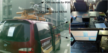
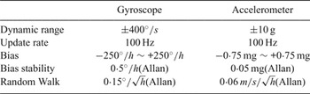
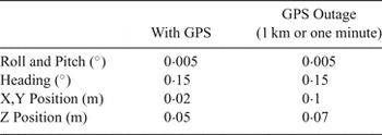
In this section, road test experiments in a land vehicle are carried out to validate and corroborate the performance of the proposed algorithm with a focus on the comparison with the traditional in-motion initial alignment method. The experimental platform is shown in Figure 1, which is composed of a MEMS Inertial Measurement Unit (MIMU, Stim-300 from the Sensonor company), GPS and a POS (Position and Orientation System, POS) system (LV-610 from the Applanix company). The POS system is a type of high-accuracy integrated navigation system. Here it is used to provide the reference attitude with high accuracy for initial alignment performance comparison. The specifications of the MIMU and the accuracy specifications of the POS are listed in Tables 1 and 2, respectively.
Setup of the experimental platform.

Specifications of the Stim-300.

Accuracy Specifications of the POS LV-610(PP).

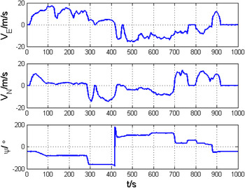
It is known that the yaw misalignment angle is not observable without horizontal accelerations. Based on attitude estimation using the vector observations algorithm, we know that all possible constraint manoeuvres should be performed to change the acceleration to change the direction of the integration vector. Therefore, after beginning alignment, the vehicle should accelerate in a straight line or make turning manoeuvres as a necessary condition for in-motion alignment. The reference yaw and velocity during the test are shown in Figure 2.
Velocity and yaw during the test.

In the experiment, the initial state covariance matrix
 ${\bi P}_{0}$
has diagonal entities of the corresponding state variances. The proposed method and the conventional fine alignment are set as follows
 $$\left\{ \matrix{ {\bi P}_0 = diag ([{\bi P}_l, {\bi P}_{\varphi^{i_b}}, {\bi P}_{\delta V^{i_b}}, {\bi P}_{\varepsilon}, {\bi P}_{\nabla}]), (proposed\,method) \hfill \cr {\bi P}_0 = diag ([{\bi P}_{\phi}, {\bi P}_{\delta v}, {\bi P}_{\delta p}, {\bi P}_{\varepsilon}, {\bi P}_{\nabla}]), (conventional\,method) } \right.$$
where
 ${\bi P}_{l_{j}}=(1)^{2}$
,
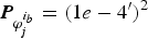 ${\bi P}_{{\bi \varphi}_{j}^{i_{b}}} = (1e - 4^{\prime})^{2}$
,
 ${\bi P}_{\delta {\bi V}_{j}^{i_{b}}} = (0{\cdot}1\hbox{m/s})^{2}$
,
 ${\bi P}_{{\bi \phi}_{j}} = (1^{\circ})^{2}$
,
 ${\bi P}_{\delta v_{j}} = (0{\cdot}1\hbox{m/s})^{2}$
,
 ${\bi P}_{\delta P} = (10\hbox{m})^{2}$
,
 ${\bi P}_{\varepsilon_{j}} = (100^{\circ}/\hbox{h})^{2}$
,
 ${\bi P}_{\nabla_{j}} = (3\hbox{mg})^{2}$
.
The two methods have the same measurement noise covariance matrix
 ${\bi R} = \hbox{diag} ([0{\cdot}1 \quad 0{\cdot}1 \quad 0{\cdot}1]^{2})$
and this is chosen based on the GPS output uncertainties. The
 ${\bi Q}$
matrix is created using the inertial sensors’ noise statistics shown in Table 1.
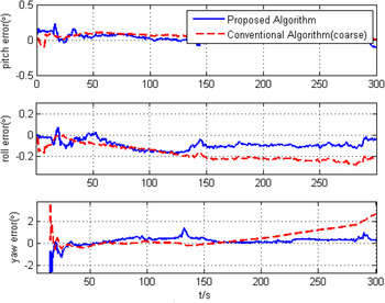
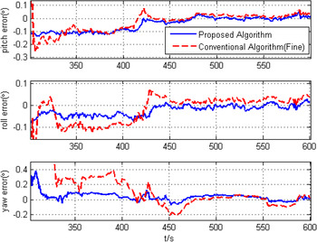
The results of our method and conventional alignment algorithm are compared to the reference POS system. Figures 3 and 4 illustrate the alignment error in the alignment process. Figure 3 shows the alignment error from 0 s to 300 s to compare the proposed method with conventional coarse alignment, while Figure 4 compares results of our method and conventional fine alignment from 300 s to 600 s.
Alignment errors comparison between the proposed method and conventional coarse alignment.

Alignment errors comparison between the proposed method and conventional fine alignment.

It is shown that the alignment performance of the proposed approach has obvious improvements compared with that of the conventional approach. In particular, the yaw estimation converges much faster and achieves higher accuracy than that of the more conventional algorithm. The results indicate that the heading could reach around
 $0{\cdot}1^{\circ}$
accuracy and the pitch and roll could be aligned up to
 $0{\cdot}05^{\circ}$
during the alignment.
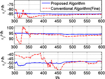
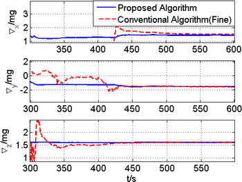
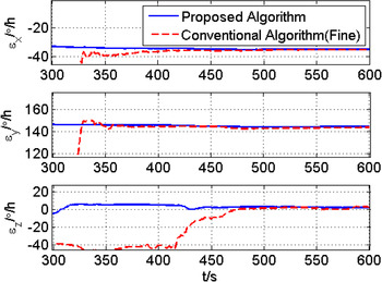
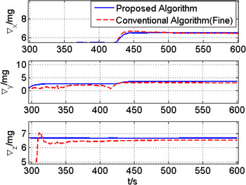
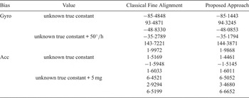
The gyroscope and accelerometer bias estimates are shown in Figures 5 and 6, respectively. Since the sensor biases have a dominating effect on the performance of initial alignment, especially for the low-cost SINS, a better knowledge of the sensor biases yields a more accurate attitude estimate. This is why the proposed approach has superior performance over the conventional algorithm. In addition, we have added 50°/h and 5 mg biases into the outputs of gyroscopes and accelerometers, respectively. We can compare the bias estimation accuracy indirectly by the biases estimation results before and after the addition. Figures 7 and 8 show the estimation results of biases after the addition, and the estimation results at the final time of alignment are summarised in Table 3.
Gyroscope biases estimation.

Accelerometer biases estimation.

Gyroscope biases estimation (unknown true constant+50°/h).

Accelerometer biases estimation (unknown true constant+5 mg).

Gyroscope and Accelerometer biases estimation results.

It is seen that the proposed approach provides a slight improvement in estimation accuracy over the classical fine alignment by comparing the bias estimation results before and after the addition. The former can reach
 $[49{\cdot}9649 \quad 50{\cdot}0626 \quad 50{\cdot}0721]^{\rm T} {}^{\circ}/ \hbox{h}$
and
 $[5{\cdot}0591 \quad 4{\cdot}9825 \quad 5{\cdot}0641]^{\rm T}\,\hbox{mg}$
respectively, whereas the latter is
 $[50{\cdot}2059 \quad 50{\cdot}2350 \quad 50{\cdot}8302]^{\rm T} {}^{\circ}/ \hbox{h}$
and
 $[4{\cdot}9352 \quad 4{\cdot}5242 \quad 4{\cdot}9166]^{\rm T}\,\hbox{mg}$
. Moreover, we also deduce that the proposed approach performs better during the steady state from Figure 5 to 8.
5. CONCLUSION
This paper describes the in-motion alignment procedure for a low-cost INS/GPS integrated system under random misalignment angles using the second order extended Kalman filter structure. Based on Rodrigues parameters representation, an alignment model with a linear system equation and second order nonlinear measurement equation is established. The second order extended Kalman filter framework enables the proposed method to estimate the gyroscope and accelerometer biases apart from the initial alignment, which is optimised for low-cost Micro Electro Mechanical System (MEMS)-based SINS.
From the experimental test results, it has been clearly indicated that the proposed alignment approach can achieve the initial alignment more quickly and more accurately compared with the conventional approaches.