1. Introduction
A virtual cathode oscillator (vircator, VCO) is one of the most potentially high-power microwave sources because of its advantages of simple structure, frequency tunability and no requirements for external magnetic field (Sullivan, Walsh & Coutsias Reference Sullivan, Walsh and Coutsias1987; Benford & Swegle Reference Benford and Swegle1992). However, the disadvantage of low power conversion efficiency limits the application of a vircator all the time. Of all the various vircator geometries investigated (Jiang et al. Reference Jiang, Shimada, Prasad and Yatsui2004; Jeon et al. Reference Jeon2006; Yang, Dong & Dong Reference Yang, Dong and Dong2010), the coaxial vircator has attracted wide attention across the world for its capability of higher power conversion efficiency and long pulse operability (Jiang et al. Reference Jiang, Woolverton, Dickens and Kristiansen1999; Liu et al. Reference Liu2008; Biswas & Kumar Reference Biswas and Kumar2010; Zhang et al. Reference Zhang2011; Roy et al. Reference Roy2012).
Although many efforts have been made in experimental studies on VCO in the past, the energy efficiency is still about several per cent, owing to the lack of theoretical assistance. In order to find the right direction for the design and optimization of an experimental configuration, many theoretical models based on one-dimensional and small-signal theory have been proposed (Jiang, Masugata & Yatsui Reference Jiang, Masugata and Yatsui1995; Jiang & Kristiansen Reference Jiang and Kristiansen2001; Shao, Liu & Yang Reference Shao, Liu and Yang2005). However, the nonlinear resonance between the electron beam and the electric field takes place under the conditions of a large signal when the microwave field in a vircator reaches saturation. Obviously, those models cannot describe the nonlinear beam–wave interaction process accurately, so it is necessary to establish a theoretical analysis model based on the large-signal conditions.
To further increase the efficiency of an original vircator, in 2002, a planar vircator with two gaps was proposed by the Institute of High Current Electronics (Kitsanov et al. Reference Kitsanov, Klimov, Korovin, Kurkan, Pegel and Polevin2002), which has proved that the microwave efficiency can be improved by beam premodulation. With the method of beam modulation by cavities studied, the coaxial vircator also developed further, such as the coaxial vircator with single-gap modulation (Kovalchuk et al. Reference Kovalchuk, Polevin, Tsygankov and Zherlitsyn2010) and the coaxial vircator with dual-cavity modulation (Yang et al. Reference Yang2013). However, it is reported that their power efficiency from the experiments still cannot reach the level required in applications. Consequently, it is necessary to carry out some research on the effect of injected current premodulation on the system efficiency to find a proper way to propose a novel vircator with enhanced modulation.
Considering that the small-signal theoretical model has some limitations in describing the nonlinear interaction, a one-dimensional theoretical model based on the large-signal condition is developed in this paper. Based on the theoretical model, the dependences of the electron phase shift and the microwave gain on the amplitude of the microwave field are obtained, and then the effect of injected current premodulation on the microwave gain is analysed. To test the validity of the theoretical predictions, a new coaxial vircator with an improved dual-cavity modulation structure, where a microwave feedback channel (Gadetskii et al. Reference Gadetskii1993) is introduced to adjust the phase difference between the modulated beam current and the microwave field in the interaction region, is proposed and studied by simulation. Compared with the similar vircator without feedback, the numerical results show that the modulation structure with microwave feedback is helpful to increase the saturated power level.
2. One-dimensional theoretical model for nonlinear resonance
Under the one-dimensional and steady-state hypothesis, an electron with energy
 $eV_{0}$
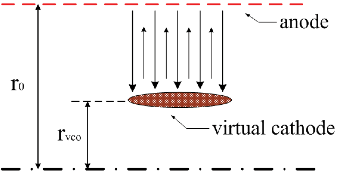
is injected into a cylindrical drift space while the virtual cathode has been formed at the position
 $r_{\mathit{vco}}$
where the potential is kept at
 ${\it\phi}=-V_{0}$
, as shown in figure 1. It is clear that the electron will be decelerated by the electric field from beam space charge as it approaches the virtual cathode and then its kinetic energy will be diminished to zero at the virtual cathode.
Assuming that an external oscillating electric field of
 $\text{TM}_{01}$
mode is applied over the cylindrical drift space, the radial electric-field component of the
 $\text{TM}_{01}$
mode can be written as
 $$\begin{eqnarray}E_{\mathit{ext}}(r,t)=E_{1}(r)\sin ({\it\omega}t+{\it\varphi})\end{eqnarray}$$
with
 $$\begin{eqnarray}E_{1}(r)=\text{J}_{1}(2.405r/r_{0})E_{\mathit{ext}0},\end{eqnarray}$$
where
 $r_{0}$
is the anode radius,
 $\text{J}_{1}$
is the first-order Bessel function,
 $E_{\mathit{ext}0}$
is the electric-field amplitude,
 ${\it\omega}$
is the oscillation frequency and
 ${\it\varphi}$
is the initial phase of the oscillating field.
A simple model for the beam–wave interaction.

Observing an electron that is injected at time
 $t=0$
with an initial momentum of
 $p_{0}$
, the velocity of the electron decreases as it moves towards the virtual cathode due to the interaction with the external oscillating electric field and the space-charge electric field. After a time
 ${\it\tau}_{1}$
, the electron arrives at the position of the virtual cathode where its momentum reaches zero and then the initial momentum
 $p_{0}$
will be given as
 $$\begin{eqnarray}p_{0}=\frac{1}{r_{\mathit{vco}}-r_{0}}\int _{r_{0}}^{r_{\mathit{vco}}}\int _{0}^{{\it\tau}_{1}}e[E_{\mathit{self}}(r,t)+E_{\mathit{ext}}(r,t)]\,\text{d}t\,\text{d}r,\end{eqnarray}$$
where
 $E_{\mathit{self}}(r,t)$
is the electric field generated by the electron space charge, which under the steady-state hypothesis can be replaced by
 $E_{\mathit{self}}(r)$
, and
 $E_{\mathit{ext}}(r,t)$
is the external oscillating electric field given by (2.1).
With the above hypothesis, the average value of
 $E_{\mathit{self}}(r)$
can be denoted as
 $$\begin{eqnarray}\overline{E}_{\mathit{self}}=\frac{V_{0}}{r_{0}-r_{\mathit{vco}}}=\frac{p_{0}}{e{\it\tau}_{0}},\end{eqnarray}$$
where
 ${\it\tau}_{0}$
(Jiang & Kristiansen Reference Jiang and Kristiansen2001; Shao et al.
Reference Shao, Liu and Yang2005) is defined as the average transit time between the injection position and the virtual cathode. From (2.4) it can also be seen that
 ${\it\tau}_{0}$
actually corresponds to the transit time in the case of a cylindrical drift space without an external oscillating electric field.
Introducing the concept of a transit time shift
 ${\it\delta}$
(Jiang & Kristiansen Reference Jiang and Kristiansen2001; Shao et al.
Reference Shao, Liu and Yang2005), the actual transit time can be expressed by
 ${\it\tau}_{1}={\it\tau}_{0}+{\it\delta}$
. Then substituting (2.4) into (2.3), the following equation can be obtained:
 $$\begin{eqnarray}{\it\omega}{\it\delta}={\it\eta}[\cos ({\it\theta}_{0}+{\it\varphi}+{\it\omega}{\it\delta})-\cos {\it\varphi}].\end{eqnarray}$$
Here
 ${\it\eta}=KE_{\mathit{ext}0}/V_{0}$
with
 $K=(r_{0}/2.405)\text{J}_{0}(2.405r_{\mathit{vco}}/r_{0})$
is the ratio of the oscillating electric-field amplitude
 $E_{\mathit{ext}0}$
and the normalized space-charge field
 $V_{0}/K$
,
 ${\it\theta}_{0}={\it\omega}{\it\tau}_{0}$
is the average transit angle and
 ${\it\omega}{\it\delta}$
is the electron phase shift.
Using the Taylor series expansion, (2.5) can be expanded as
 $$\begin{eqnarray}{\it\omega}{\it\delta}={\it\eta}\left[\cos ({\it\theta}_{0}+{\it\varphi})-\cos {\it\varphi}-{\it\omega}{\it\delta}\sin ({\it\theta}_{0}+{\it\varphi})-\frac{({\it\omega}{\it\delta})^{2}}{2}\cos ({\it\theta}_{0}+{\it\varphi})+\cdots \right].\end{eqnarray}$$
Under the small-signal condition, namely
 $E_{\mathit{ext}0}\ll \overline{E}_{\mathit{self}}$
, the solution to (2.5) can be linearly approximated as
 $$\begin{eqnarray}{\it\omega}{\it\delta}=-2{\it\eta}\sin \left(\frac{{\it\theta}_{0}}{2}\right)\sin \left({\it\varphi}+\frac{{\it\theta}_{0}}{2}\right),\end{eqnarray}$$
which is the analytical solution obtained from the small-signal theoretical model (Jiang & Kristiansen Reference Jiang and Kristiansen2001; Shao et al. Reference Shao, Liu and Yang2005).
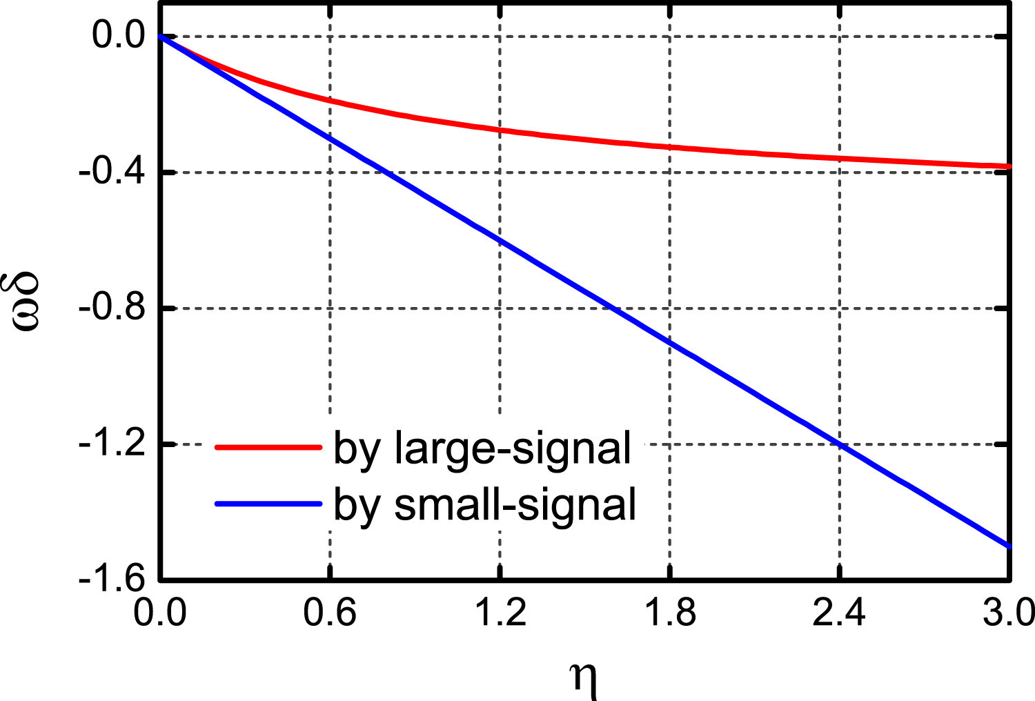
Solving (2.5) with the small- and large-signal theory, respectively, the results are given in figure 2. It can be seen that the phase shift always increases linearly with the microwave field according to the small-signal theory. However, the large-signal theory shows that the electron phase shift increases sharply with the electric field ratio
 ${\it\eta}$
only in the initial stage of the beam–microwave interaction. The curve becomes gentle and even almost flat as the amplitude of the microwave field increases to a certain extent. By comparison, it can be found that the analytical solution given by (2.7) is just applicable in the process of linear resonance.
Electron phase shift as a function of the electric field ratio
 ${\it\eta}$
.

Considering the beam–wave interaction between the electron beam and the large-amplitude oscillating electric field, it is obvious that the analytical solution given by (2.7) has been inapplicable, for which the high orders of (2.6) cannot be neglected. Therefore, the electron phase shift should be solved by the large-signal theory in the stage of nonlinear resonance between the electron and the oscillating electric field.
After time
 ${\it\tau}_{2}$
, the electron will be reflected back to the injection position, where its momentum becomes
 $p$
, which can be written as
 $$\begin{eqnarray}p=\frac{1}{r_{0}-r_{\mathit{vco}}}\int _{r_{\mathit{vco}}}^{r_{0}}\int _{{\it\tau}_{1}}^{{\it\tau}_{1}+{\it\tau}_{2}}e[E_{\mathit{self}}(r)+E_{\mathit{ext}}(r,t)]\,\text{d}t\,\text{d}r.\end{eqnarray}$$
Using (2.3) and (2.8), the average electron momentum loss that results from the interaction between the electron beam and the external electric field in an oscillating period can be described as
 $$\begin{eqnarray}\displaystyle \overline{\left(\frac{p_{0}-p}{p_{0}}\right)} & = & \displaystyle \frac{1}{2{\rm\pi}p_{0}}\int _{0}^{2{\rm\pi}}\frac{e}{r_{\mathit{vco}}-r_{0}}\left\{\int _{r_{0}}^{r_{\mathit{vco}}}\left[\int _{0}^{{\it\tau}_{1}}E_{\mathit{self}}(r)+E_{\mathit{ext}}(r,t)\,\text{d}t\right.\right.\nonumber\\ \displaystyle & & \displaystyle \left.\left.\!-\int _{{\it\tau}_{1}}^{{\it\tau}_{1}+{\it\tau}_{2}}E_{\mathit{self}}(r)+E_{\mathit{ext}}(r,t)\,\text{d}t\right]\text{d}r\right\}\text{d}{\it\varphi}.\end{eqnarray}$$
Using the assumption of
 ${\it\tau}={\it\tau}_{1}={\it\tau}_{2}$
(Jiang & Kristiansen Reference Jiang and Kristiansen2001; Shao et al.
Reference Shao, Liu and Yang2005), the average electron momentum loss in an oscillating period can be reduced to
 $$\begin{eqnarray}\displaystyle \overline{\left(\frac{p_{0}-p}{p_{0}}\right)} & = & \displaystyle \frac{1}{2{\rm\pi}p_{0}}\int _{0}^{2{\rm\pi}}\frac{e}{r_{\mathit{vco}}-r_{0}}\left\{\int _{r_{0}}^{r_{\mathit{vco}}}E_{1}(r)\,\text{d}r\left[\int _{0}^{{\it\tau}}\sin ({\it\omega}t+{\it\varphi})\,\text{d}t\right.\right.\nonumber\\ \displaystyle & & \displaystyle \left.\left.\!-\int _{{\it\tau}}^{2{\it\tau}}\sin ({\it\omega}t+{\it\varphi})\,\text{d}t\right]\right\}\text{d}{\it\varphi}.\end{eqnarray}$$
Then substituting (2.1) into (2.10), a simpler form of (2.10) can be written as
 $$\begin{eqnarray}\overline{\left(\frac{p_{0}-p}{p_{0}}\right)}=-\frac{2{\it\eta}}{{\rm\pi}{\it\theta}_{0}}\int _{0}^{2{\rm\pi}}\sin ^{2}\frac{{\it\theta}_{0}+{\it\omega}{\it\delta}}{2}\cos ({\it\theta}_{0}+{\it\varphi}+{\it\omega}{\it\delta})\,\text{d}{\it\varphi}.\end{eqnarray}$$
From (2.11), it can be seen that the electron phase shift has a great effect on the power efficiency, which is due to the fact that the phase relation between the electric field and the beam current is related to the electron phase shift. Therefore, the electron phase shift in (2.11) should be obtained by the large-signal theory so as to describe the characteristic of resonance more clearly.
If the momentum loss is positive, the external oscillating electric field will obtain energy from the electron; otherwise the electric field will give out energy to the electron. Obviously, the change of the electron momentum in an oscillating period is a result of the energy exchange between the injected electron beam and the microwave field. So (2.11) also represents the microwave gain of resonance between the electron and the oscillating electric field.
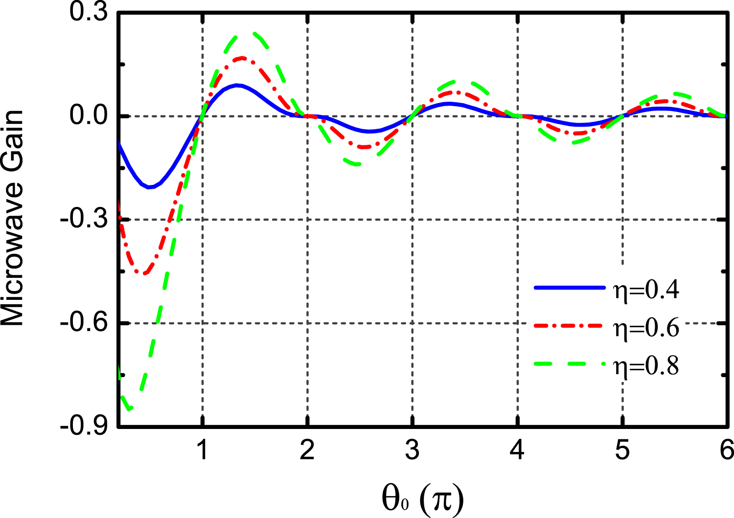
Using (2.11), the dependence of the microwave gain on the average transit angle
 ${\it\theta}_{0}$
is given by figure 3. It shows that the positive and negative value ranges of the microwave gain exist alternately and periodically. The maximum of the microwave gain is sensitive to the amplitude of the external oscillating electric field.
Microwave gain as a function of
 ${\it\theta}_{0}$
for different values of
 ${\it\eta}$
.

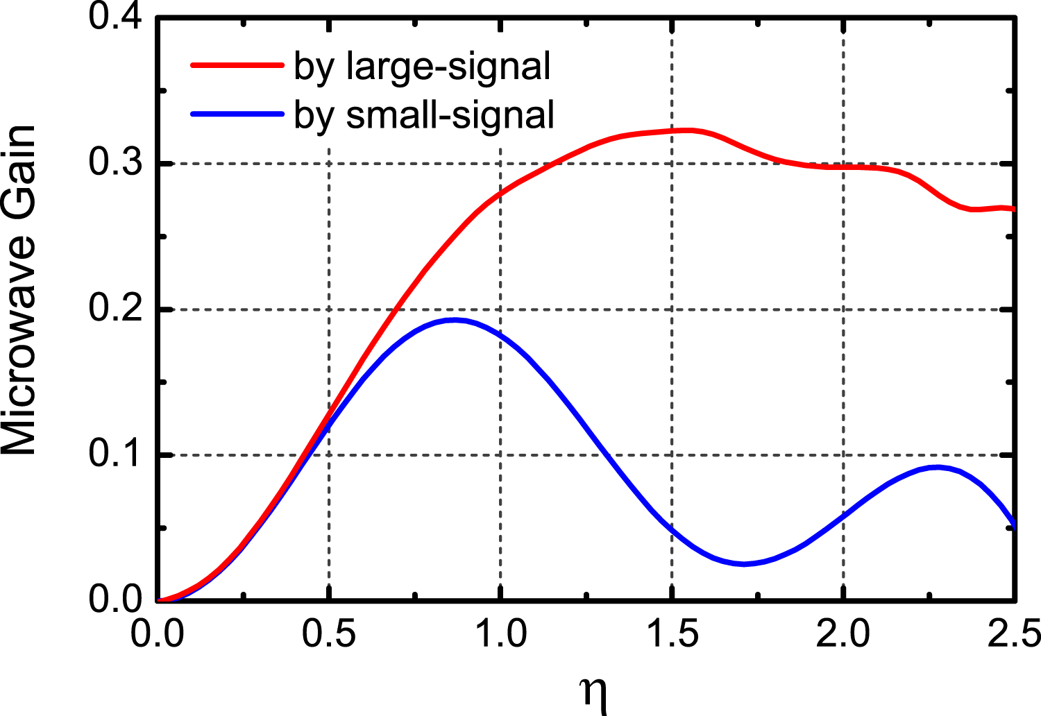
For comparison, the dependences of the microwave gains obtained from the small- and large-signal theoretical model, respectively, on the ratio of the oscillating electric-field amplitude and the normalized space-charge field
 ${\it\eta}$
are given in figure 4. It can be seen that both the microwave gains increase almost linearly with
 ${\it\eta}$
during the process of resonance between the electron beam and the small-amplitude oscillating electric field.
Microwave gain as a function of
 ${\it\eta}$
.

When the resonance between the electron beam and the large-amplitude oscillating field occurs, it can be found that both the microwave gains approach their peaks gradually and then start to fall, which indicates that the modulation amplitude of the beam current is approaching saturation. As a result, the electron phase shift becomes overlarge and the phase difference between the beam current and the oscillating field will be affected. However, owing to the slight effect of the microwave field on the electron phase shift in the situation of nonlinear resonance, the microwave gain just decreases more gradually. Consequently, from figure 4, it is also seen that the curve from the large-signal model changes more gently compared with the curve of the small-signal model.
3. Effect of injected beam current premodulation on efficiency
For simplicity, supposing that the electron beam current has been modulated before being injected into the interaction region and the modulation frequency is equal to the frequency of the microwave field, the modulated beam current can be written as
 $$\begin{eqnarray}I_{in}=I_{0}[1+{\it\xi}\sin ({\it\omega}t+{\it\varphi}+{\rm\Delta}{\it\varphi})],\end{eqnarray}$$
where
 $I_{0}$
is the time-averaged value of the injected current,
 ${\it\xi}$
is the premodulation amplitude and
 ${\rm\Delta}{\it\varphi}$
is the phase difference between the modulated beam current and the microwave field.
According to (3.1), the number of electrons injected into the interaction region at time
 $t=0$
is given by
 $$\begin{eqnarray}n(0)=I_{0}/e[1+{\it\xi}\sin ({\it\varphi}+{\rm\Delta}{\it\varphi})].\end{eqnarray}$$
Using (2.10) and (3.2), the average microwave gain of the interaction between the modulated electron beam and the oscillating electric field can be written as
 $$\begin{eqnarray}\displaystyle \overline{\left(\frac{p_{0}-p}{p_{0}}\right)} & = & \displaystyle \frac{\displaystyle \int _{0}^{2{\rm\pi}}\!\left\{\displaystyle \frac{n(0)e}{r_{\mathit{vco}}-r_{0}}\int _{r_{0}}^{r_{\mathit{vco}}}\!E_{1}(r)\,\text{d}r\left[\displaystyle \int _{0}^{{\it\tau}}\!\sin ({\it\omega}t+{\it\varphi})\,\text{d}t-\!\int _{{\it\tau}}^{2{\it\tau}}\!\!\sin ({\it\omega}t+{\it\varphi})\,\text{d}t\right]\right\}\text{d}{\it\varphi}}{p_{0}\displaystyle \int _{0}^{2{\rm\pi}}\!n(0)\,\text{d}{\it\varphi}}\nonumber\\ \displaystyle & = & \displaystyle \frac{2{\it\eta}}{{\rm\pi}{\it\theta}_{0}}\int _{0}^{2{\rm\pi}}[1+{\it\xi}\sin ({\it\varphi}+{\rm\Delta}{\it\varphi})]\sin ^{2}\frac{{\it\theta}_{0}+{\it\omega}{\it\delta}}{2}\cos ({\it\theta}_{0}+{\it\varphi}+{\it\omega}{\it\delta})\,\text{d}{\it\varphi}.\end{eqnarray}$$
Comparing this with (2.11), it can be seen that the interaction between the modulation component of the beam current and the microwave field will bring about an additional microwave gain, which is determined by the premodulation amplitude and the phase difference between the modulated beam current and the microwave field.
Using
 ${\it\eta}=0.6$
and
 ${\it\xi}=0.6$
, the microwave gain as a function of
 ${\it\theta}_{0}$
for different values of
 ${\rm\Delta}{\it\varphi}$
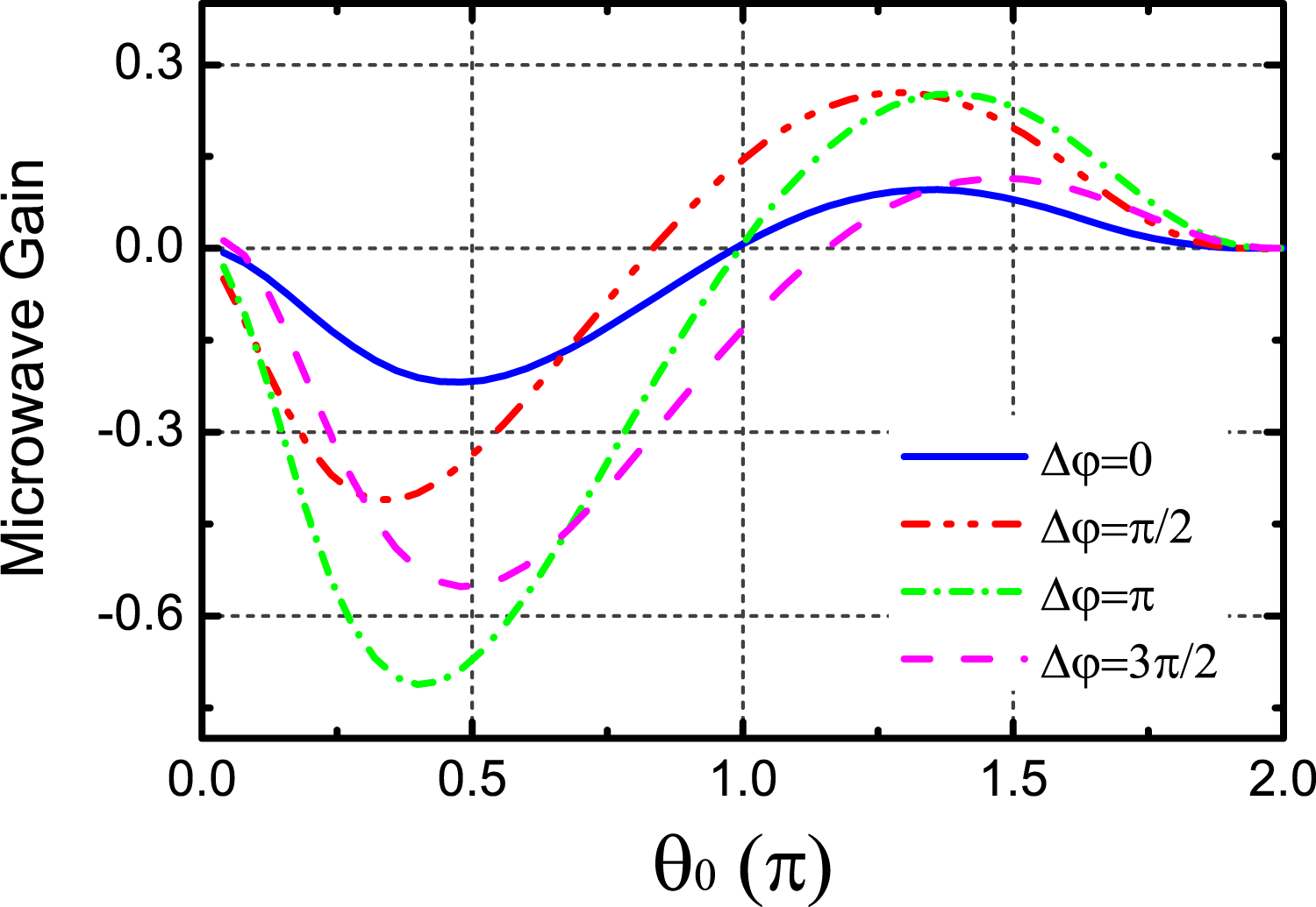
can be plotted as in figure 5. It can be seen that
 ${\rm\Delta}{\it\varphi}$
has an important effect on the maximum of the microwave gain and its corresponding optimal
 ${\it\theta}_{0}$
.
Microwave gain as a function of
 ${\it\theta}_{0}$
for different values of
 ${\rm\Delta}{\it\varphi}$
.

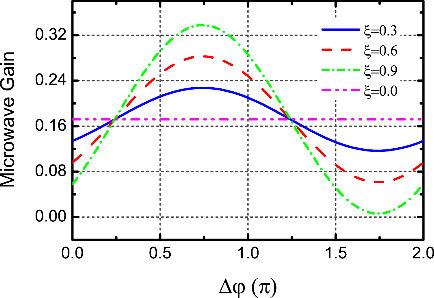
Furthermore, figure 6 gives the microwave gain as a function of
 ${\rm\Delta}{\it\varphi}$
for different values of
 ${\it\xi}$
. It shows that the gain varies periodically with
 ${\rm\Delta}{\it\varphi}$
and increases in amplitude with increasing
 ${\it\xi}$
. Meanwhile, the microwave gain can increase in the range of
 $0.22{\rm\pi}{-}1.22{\rm\pi}$
and will reach their peaks at the position of
 ${\rm\Delta}{\it\varphi}=0.72{\rm\pi}$
, etc. Obviously, this is independent of the premodulation amplitude.
Microwave gain as a function of
 ${\rm\Delta}{\it\varphi}$
for different values of
 ${\it\xi}$
.

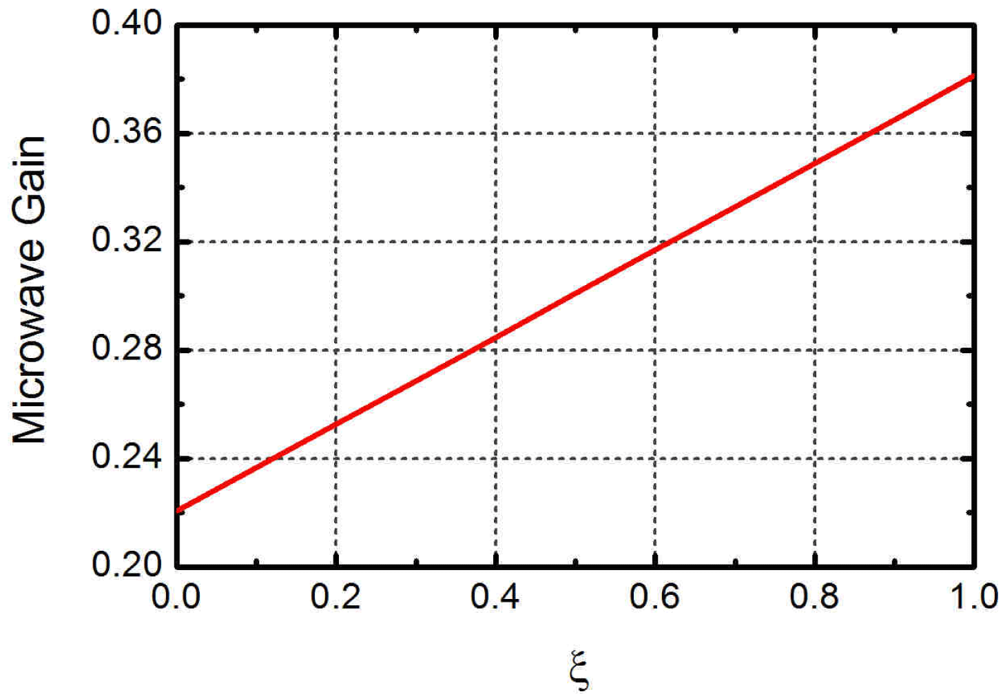
Using
 ${\rm\Delta}{\it\varphi}=0.45{\rm\pi}$
, figure 7 gives the microwave gain as a function of premodulation amplitude, and it shows that the microwave gain increases almost linearly with
 ${\it\xi}$
, which indicates that the increased modulation of the electric beam can effectively improve the power efficiency.
Microwave gain as a function of
 ${\it\xi}$
.

According to the relation between the electron momentum and electron energy efficiency, which is given by
 $$\begin{eqnarray}E_{k}=p^{2}/2m_{0},\end{eqnarray}$$
where
 $E_{k}$
is the electron energy,
 $p$
is the electron momentum and
 $m_{0}$
is the electron mass, the power efficiency of a coaxial vircator can be derived as
 $$\begin{eqnarray}G_{p}=\frac{{p_{0}}^{2}-(p_{0}-{\rm\Delta}p)^{2}}{{p_{0}}^{2}}=2G_{s}-{G_{s}}^{2}\end{eqnarray}$$
where
 $G_{p}$
is the power efficiency of the vircator and
 $G_{s}$
is the microwave gain.
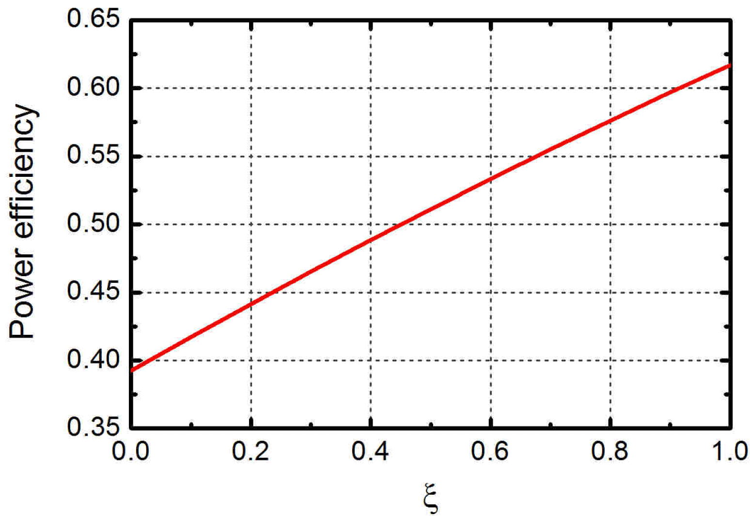
Using (3.5), figure 7 can be converted into the power efficiency versus
 ${\it\xi}$
, as shown in figure 8. It can be seen that the impact factor of the modulation depth on the power efficiency is 0.224, which means that every increase of 0.1 in the modulation depth should add an increase of 2.24 percentage points in the power efficiency.
Power efficiency as a function of
 ${\it\xi}$
.

Generally speaking, for an ordinary vircator, the incident electron beam is mainly modulated by the reflected beam and such beam modulation is usually weak, so the power efficiency of an ordinary vircator is relatively low. The above theoretical analysis shows that the injected e-beam premodulation can be used as an effective way to reinforce the beam–microwave interaction and the power efficiency will be further enhanced by adjusting the phase difference between the injected current and the microwave field in the beam–wave interaction region.
4. Numerical simulation and discussion
With the aim to increase the power efficiency, a coaxial vircator with enhanced premodulation is presented in this paper, which is an improvement of the coaxial vircator with radial dual-cavity premodulation (Yang et al. Reference Yang2013). In this improved configuration, shown in figure 9(b), a radial dual-cavity modulation structure between the diode and the interaction region is introduced to realize a high modulation efficiency and the ability to tune the microwave frequency (Yang et al. Reference Yang2013). Compared with the original vircator in figure 9(a), a microwave feedback channel (Gadetskii et al. Reference Gadetskii1993) between the modulation cavity and the interaction region is established to guide a part of the microwave field generated by the beam–wave interaction into the modulation cavity, which is expected to reinforce the beam–microwave interaction and eventually realize a higher power conversion efficiency.
The coaxial vircator (a) without feedback microwave structure and (b) with feedback microwave structure.

To study the main characteristics of the interaction between the electron beam and the microwave field, figure 10 shows the variation of the modulation amplitude of the beam current near the virtual cathode versus time. It can be seen that the curve of the modulation amplitude will become gentle as the microwave field obtains energy from the electron beam. Meanwhile, figure 2 shows that the electron phase shift caused by the microwave field will also increase to a saturated value as the microwave field increases to a certain extent, which actually indicates that the modulation of the beam current is approaching saturation. Obviously, the predictions from the large-signal theory are in accordance with the numerical results from figure 10, so the results from the proposed theory are helpful to add to our understanding of the vircator.
Variation of the modulation amplitude versus time.

In addition, the variation of the power efficiency at the operating frequency versus time is given in figure 11. It can be seen that the power efficiency will increase gently and may even saturate as the microwave field obtains energy from the electron beam, which also agrees with the description from the large-signal theory model from figure 4.
Variation of the normalized power efficiency versus time.

With the microwave feedback channel introduced, some of the microwaves from the beam–microwave interaction will be coupled into the modulation cavity through the microwave feedback channel, which will affect the oscillating field inside the modulation cavity. For easy analysis, the path that the feedback microwaves travel along is simplified as the feedback line shown by figure 12. If a feedback microwave with wavelength
 ${\it\lambda}$
and phase
 ${\it\phi}_{1}$
enters the feedback channel at point A, the phase of the wave arriving at point B in the modulation cavity will become
 ${\it\phi}_{1}-2{\rm\pi}(D_{1}+D_{2}+L)/{\it\lambda}$
. Supposing that an original oscillating field with phase
 ${\it\phi}_{2}$
exists at point B while the coherent condition is satisfied, the phase
 ${\it\phi}_{B}$
of the total field at point B satisfies
 $$\begin{eqnarray}\tan ({\it\phi}_{B})=\frac{E_{1}\sin ({\it\phi}_{1}-2{\rm\pi}(D_{1}+D_{2}+L)/{\it\lambda})+E_{2}\sin ({\it\phi}_{2})}{E_{1}\cos ({\it\phi}_{1}-2{\rm\pi}(D_{1}+D_{2}+L)/{\it\lambda})+E_{2}\cos ({\it\phi}_{2})},\end{eqnarray}$$
where
 $E_{1}$
is the feedback field amplitude and
 $E_{2}$
is the original oscillating field amplitude at point B. Obviously, the phase of the field in the modulation cavity is tied to the parameters of the feedback line, which also in turn affects the phase of the injected e-beam as a result of the modulation. In other words, the phase difference between the microwave field and the e-beam current entering the interaction region can be adjusted by changing the distance
 $D$
between the left edge of the microwave feedback channel to the reflector in the interaction region and the radial length
 $L$
.
Simplified feedback line model.

Based on the above analysis, using
 $L=29~\text{mm}$
and adjusting the phase of the injected beam current by changing
 $D$
, the variation of power conversion efficiency versus
 $D$
is given in figure 13. It can be seen that the trend of the curve is similar to the theoretical prediction shown in figure 6, which indicates that the power efficiency can be further increased when the phase difference between the modulated beam current and the microwave field reaches its proper range.
Variation of the modulation amplitude versus time.

Considering the microwave feedback structure with
 $D=37~\text{mm}$
and
 $L=27~\text{mm}$
, the comparison between the beam current spectra after passing through the modulation cavity with and without microwave feedback is shown in figure 14. It shows that the modulation frequency of the beam current is hardly influenced by microwave feedback and the modulation amplitude has been increased from 0.59 to 0.72 after adding a microwave feedback channel. Therefore, introducing the modulation cavity with the microwave feedback is also a useful way to enhance the amplitude of the beam modulation.
Spectra of beam current through modulation cavity (a) without microwave feedback and (b) with microwave feedback.

According to figure 8, it can be estimated that an extra power of 1.04 GW may be added under an input power of 36 GW if the modulation amplitude is increased from 0.59 to 0.72. To test the validity of the theoretical prediction, the new structure of a coaxial vircator with enhanced modulation has been simulated by a 2.5-D version of PIC-code, MAGIC. The simulation results show that the improved coaxial vircator may generate an average output power of 7.05 GW at 2.95 GHz and the power efficiency may reach 19.5 % with an input electron beam of 600 kV voltage and 60 kA current, as shown in figure 15.
Simulation results obtained from the improved structure corresponding to (a) instantaneous output microwave power, (b) radial electric field, (c) averaged output power and (d) frequency spectrum of radial electric field.

At the same time, the structure in figure 9(a) is also simulated with the same input parameters for comparative study. The results in figure 16 show that it can generate an average output power of 6.25 at 2.95 GHz. Comparing the numerical results from figures 15(c) and 16(a), it can also be seen that the output power of the new vircator exceeds that of the older one by an extra power of 0.8 GW, which indicates that increased modulation of the e-beam is an effective way to increase the power output.
Simulation results obtained from the unimproved structure corresponding to (a) averaged output microwave power and (b) frequency spectrum of radial electric field.

From the above simulation results, it can be understood that the microwave feedback structure helps to increase the modulation of the injected e-beam, resulting in larger energy extraction. At the same time, it can also be observed that the rise time of the output pulse has been reduced and the spectrum seems more pure after introducing the microwave feedback structure.
5. Conclusion
Based on the large-signal theory, a one-dimensional theoretical model is developed to describe the characteristics of nonlinear resonance in a coaxial vircator. It indicates that the electron phase shift will increase slightly with the microwave field in the stage of nonlinear resonance and at the same time the microwave gain approaches its peak gradually and it will decline gently when the phase shift becomes overlarge.
The effect of the injected current premodulation on the microwave gain is discussed. According to the results of the analysis, the microwave gain will change with the phase difference between the modulated current and the microwave field periodically and the proper phase difference range is about
 $0.22{\rm\pi}{-}1.22{\rm\pi}$
. In addition, the microwave gain will increase almost linearly with the premodulation amplitude, which indicates that enhancing the modulation amplitude of the beam current should be helpful to increase the power efficiency.
Based on the coaxial vircator with radial dual-cavity premodulation, a new coaxial vircator with enhanced modulation, whose structure is capable of adjusting the phase difference between the modulated beam current and the microwave field by means of microwave feedback, is presented. The numerical results show that the modulation efficiency can be increased by 22 % after introducing the microwave feedback structure.
Finally, in order to test the validity of the modulation structure with feedback, a comparison between the improved and unimproved vircator model is made by numerical simulation. The simulation results indicate that, with the microwave feedback structure introduced, the output power can be increased from 6.25 GW to 7.05 GW with the same input power and the spectrum seems cleaner.