Introduction
The diminishing availability of fossil fuels and the increasing emissions of carbon dioxide have spurred burgeoning research activity toward alternative and sustainable energy sources. Improved process efficiency for energy savings, untapped energy sources (e.g., utilization of remote and offshore natural gas reserves), renewables (e.g., solar energy, biomass conversion), and carbon dioxide capture followed by sequestration or utilization will all be important contributors to our future energy portfolio.1 Solid materials will be central more than ever in the endeavor of energy production and storage,2 but increased precision in molecular architecture and tailor-made multi-functionality will also be required.Reference Vlachos, Chen, Gorte, Huber and Tsapatsis3
The substantial economic growth of the developed world has relied heavily on its chemical and petrochemical industry. At the heart of a chemical plant lies the chemical reactor, converting raw materials into valuable chemicals and fuels. A major fraction of chemical reactions are carried out on heterogeneous catalysts. Upstream and/or downstream separations complete the major physical and chemical operations. A separation example entails purification of hydrogen from carbon monoxide to avoid poisoning of the fuel cell catalyst. Low-temperature separation processes using, for example, microporous (pore size < 2 nm) and mesoporous (pore size > 2 nm) membranes and multi-scale, multi-functional catalytic materials will be key in converting carbon neutral resources, such as biomass and its derivatives (e.g., glucose, fructose), to chemicals and fuels.Reference Vlachos, Chen, Gorte, Huber and Tsapatsis3
This article delivers a perspective of the computational-based design of emergent nanocatalysts for thermochemical transformations that can be used for the improved efficiency of existing industrial processes, biomass processing to renewable chemicals and fuels, and the utilization of untapped energy sources. In addition, mechanistic insights into the formation of such nanomaterials are discussed, with an emphasis on colloidal growth of metal nanoparticles. Understanding nucleation and growth can lead to the control of nanoparticles at the atomic level for improved catalyst activity and selectivity.
Catalyst design for thermochemical transformations
In this section, we provide an overview of computational advances in the rational design of catalytic materials. We highlight strategies for the discovery of very active bimetallic catalysts and adsorption models that account for nanoparticle characteristics.
Traditional catalyst discovery
The selection of catalysts has traditionally been based on trial and error. The introduction of high throughput experimentation several years ago has delivered unprecedented speed on materials screening; yet the combinatorial problem of mixing elements of the periodic table and a lack of understanding have limited the success of a purely experimentally driven, high throughput materials discovery approach. High-performance computation promises to facilitate efficient catalyst screening while providing a fundamental understanding of reaction mechanisms and materials properties.
Simulation engines for prediction of new catalysts
The application of density functional theory (DFT), since the mid-1990s, has made major inroads in our understanding of catalytic reactions. As a result, reasonable accuracy on energetics, including binding energies (BEs) (the strength of adsorption of species on surfaces) and reaction barriers (the energy difference between reactant and transition state energy), are routinely achieved, at least for small adsorbates on well-defined single crystal metal slabs.
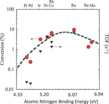
Due to differences in BEs between species, it is often the case that one species dominates on catalyst sites. As a result, the activity of a catalyst often correlates with a single adsorbate BE (a single descriptor), as shown in Figure 1, and exhibits a maximum (a so-called volcano curve). The optimum BE value strikes a balance with reagents staying long enough on the surface to react without blocking catalyst sites (Sabatier’s principle).
Ammonia decomposition volcano curve (i.e., conversion versus atomic nitrogen binding energy). The ammonia conversion is calculated from microkinetic (detailed surface mechanism) modeling (red circles) for various transition metal catalysts. Experimental supported catalyst turnover frequencies (TOF) (black triangles).Reference Ganley, Thomas, Seebauer and Masel23 The dotted line was calculated by assuming average interaction energies as described in Reference 7.

To improve catalyst activity or reduce the cost of expensive noble metals used, bimetallic catalysts may be used. Given BEs of the key intermediate on a handful of metals of the periodic table and the corresponding volcano curve, the composition of mixed alloys can be predicted by simple interpolation. The interpolation principle was successfully used for the first time to propose a CoMo catalyst in ammonia synthesis from BE calculations of N on Co and Mo slabs. Mo, a high nitrogen binding energy metal, and Co, a low binding energy metal, were selected to give a system with an intermediate binding energy (in reality, upon exposing the system to ammonia, a Co3Mo3N structure forms a structure that differs from the one upon which predictions were based).Reference Jacobsen, Dahl, Clausen, Bahn, Logadottir and Norskov4 Another example of this approach includes the prediction of Fe-Ni alloys that are superior and less costly to Ni in the methanation reaction (conversion of CO to methane via the reaction CO + 3H2 → CH4 + H2O that can be used for cleanup of a H2 stream from CO).Reference Nørskov, Bligaard, Rossmeis and Christensen5
An even more important attribute of a catalyst is its selectivity. This refers to the fraction of a desirable product among all products formed. Improved selectivity reduces the need for energy intensive separations necessary for product purification. Maximum selectivity does not follow Sabatier’s principle, and as a result, there is no general method for predicting catalysts of high selectivity. For simple systems, where a reactant is consumed via two parallel pathways, the difference in activation energies of these pathways can be used as a measure of selectivity. Identification of selective bimetallics requires the computation of activation energies for this pair of reactions for a library of bimetallics. An example of this approach has been demonstrated in ethylene epoxidationReference Linic, Jankowiak and Barteau6 and selective acetylene hydrogenation.Reference Nørskov, Bligaard, Rossmeis and Christensen5 Improved selectivity by development of novel catalysts leads to enhanced overall energy efficiency due to the reduced need for separation downstream of a chemical reactor (separations are typically very energy-intensive processes). While encouraging, this approach is difficult to generalize to complex networks and when reactor scale phenomena are important (Figure 2).
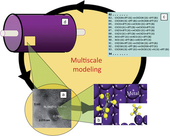
Schematic of multiscale modeling. (a) High-resolution transmission electron micrograph of Ru nanoparticles on γ-Al2O3 indicating distinct facets. The particle size and shape is controlled from synthesis and operating conditions of the reactor depicted in (d). (b) Density functional theory (DFT) unit cell on a catalyst facet to compute binding energies and reaction barriers. The output of DFT is input into detailed reaction mechanisms shown in (c). (c) Schematic of a microkinetic model. This model is input into a chemical reactor model. (d) Schematic of a chemical reactor. The chemical reactor calculation provides activity and selectivity as functions of operating conditions.

The CoMo bimetallic catalyst just discussed was predicted through the concept of periodic table interpolation.Reference Jacobsen, Dahl, Clausen, Bahn, Logadottir and Norskov4 Inherent to the interpolation principle is the assumption that the resulting alloy is well mixed. Obviously, this approach misses bimetallics, whereby one metal segregates to the surface and other metastable structures. For such systems, surface properties may exhibit vastly different properties from a well-mixed alloy.
One such atomic structure is a monolayer bimetallic catalyst with a monolayer of a metal either in the top or the second layer of a host metal (see schematics in Table I). Both structures exhibit emergent behavior (i.e., their properties cannot be predicted from those of the parent metals). Recently, a method was proposed to rationally design these novel catalysts. First, one picks common crystallographic planes (Figure 2a and 2b) to perform DFT calculations and develop detailed reaction mechanisms (Figure 2c) for reactor calculations (Figure 2d). In this multiscale framework, information across scales (from the electronic scale studied via DFT to the macroscopic, reactor scale) is integrated seamlessly. This calculation is repeated for a number of materials in order to construct the volcano curve (Figure 1).
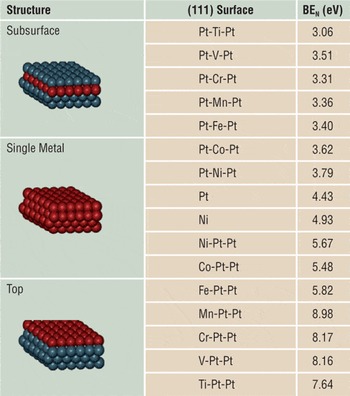
Atomic Nitrogen binding energy on bimetallic surfaces.

Library of density functional theory binding energies (BEs) of atomic nitrogen (N) at a 1/9th monolayer (coverage on various monolayer bimetallic surfaces on a Pt(111) host). The BE of N on bimetallic surfaces varies widely.
Subsequently, a library of BEs is built for the key intermediate using DFT for various molecular architectures (pairs of metals and structures) (e.g., top surface and sub-surface). This database is subsequently searched to identify a combination (e.g., top or subsurface) on which the BE is close to that of the maximum activity of the volcano curve. An example, using Pt(111) as the host, is shown in Table I. This approach does not rely on interpolation of the periodic table and led to the discovery of NiPt (Ni on the top), which was indeed found experimentally to exhibit the highest catalyst activity known today for ammonia decomposition to hydrogen for fuel cells.Reference Hansgen, Vlachos and Chen7
Adsorption on nanoparticles
The BE of an adsorbate is not only affected by the catalyst composition (metal or pair of metals) and architecture (e.g., surface or subsurface configuration) but also from the shape and size of a nanoparticle. Examples underscoring the importance of nanoparticle shape on catalyst activity have been recently reported.Reference Karim, Prasad, Mpourmpakis, Lonergan, Frenkel, Chen and Vlachos8, Reference Bratlie, Lee, Komvopoulos, Yang and Somorjai9 Our ability to predict tailor-made catalysts lies in the ability to develop nanoscale models that account for nanoparticle size and shape effects.
Subnanometer catalysts do not expose well-defined planes but rather low-coordinated sites that determine the BE of an adsorbate. The general trend is that the adsorbate BE affinity increasesReference Mpourmpakis and Vlachos10 with decreasing metal coordination number. On molecular scale catalysts (metal clusters consisting of only a few atoms), the strongest binding site is related to the localization of the HOMO and LUMO orbitals (highest occupied and lowest unoccupied molecular orbitals, respectively) on the clusters.Reference Chretien, Buratto and Metiu11 The HOMO and LUMO orbitals are usually localized on the lowest coordinated site of a cluster. Aside from the localization, the directionality of the orbitals plays a pivotal role, especially in CO binding. It becomes apparent that the complexity of the adsorption increases with decreasing nanoparticle size since the electronic properties of the metal become gradually more important.Reference Mpourmpakis and Vlachos10, Reference Chretien, Buratto and Metiu11
This materials gap (adsorption and catalyst activity varying with nanoparticle size and shape) is one of the reasons currently hindering our ability to understand and eventually control catalytic chemistry at various scales. As a result, the development of first-principle models taking into consideration the structure, composition, size, and shape of the nanoparticles will be invaluable.
Such a model was recently developed for the CO adsorption on Au nanoparticles.Reference Mpourmpakis, Andriotis and Vlachos12 The CO oxidation on Au, a reaction of high interest over the last two decades,Reference Haruta, Kobayashi, Sano and Yamada13 is a structure-sensitive reaction. The consensus emerging is that only low coordinated sites of the nanoparticles are catalytically active.Reference Hvolbaek, Janssens, Clausen, Falsig, Christensen and Norskov14 In the proposed model,Reference Mpourmpakis, Andriotis and Vlachos12 two suitable descriptors were identified, namely, the coordination number and the curvature angle of the surface Au atoms, capable of predicting the CO BE on every site of Au nanoparticles. The model captures the nanoparticle characteristics, such as size, shape, symmetry, and electronic properties. Such models can eventually be used to predict optimal size, shape, and symmetry of nanocatalysts.
Catalyst synthesis
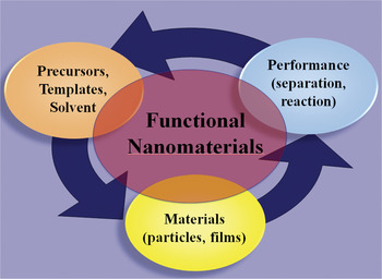
The previous examples illustrate how modeling can be used in inverse problems, for identification of architecture, as well as structural and electronic properties. Our ability to design catalysts from first principles also relies heavily on understanding the mechanisms and predicting conditions and reagents that impart desired nanoparticle size and shape, as illustrated in Figure 3. In this section, we describe recent advances in computational modeling of nanoparticle growth.
Schematic illustration of materials design. Simulations typically follow the arrows. In materials design, one inverses the direction (i.e., given desirable performance characteristics of a chemical reactor or a separation unit) (right ellipsoid), materials are identified (central ellipsoid), followed by synthesis conditions (left ellipsoid) that lead to fabrication of nanomaterials with desirable attributes.

Modeling nanoparticle growth
While major advances in the experimental synthesis of nanomaterials have recently been achieved,Reference Caswell, Bender and Murphy15, Reference Jadzinsky, Calero, Ackerson, Bushnell and Kornberg16 computations describing catalyst synthesis and the underlying nucleation and growth processes lag behind. This is, in part, due to the multi-component nature of the complex environment in which synthesis typically proceeds, the fact that nucleation is a rare event, and the complexity of growth mechanisms and structural evolution of nanoparticles with growing size. Notable examples of computations attempting to handle synthesis include nucleation and growth of zeolitesReference Caratzoulas, Vlachos and Tsapatsis17, Reference Nikolakis, Kokkoli, Tirrell, Tsapatsis and Vlachos18 and more recently of metals in colloidal systems,Reference Mpourmpakis, Caratzoulas and Vlachos19–Reference Mpourmpakis and Vlachos21 as well as the formation of carbon nanotubes.Reference Andriotis, Menon and Froudakis22
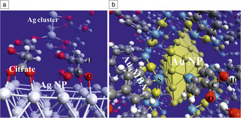
Modeling can provide molecular-level insights into growth mechanisms.Reference Caratzoulas, Vlachos and Tsapatsis17–Reference Andriotis, Menon and Froudakis22 For instance, in the growth of silver nanoparticles, the citrate, which is used as a capping agent to stump growth, was found to open up new growth channels either during nucleation of small clustersReference Mpourmpakis and Vlachos20 or during growth on the nanoparticle surfaceReference Mpourmpakis and Vlachos21 (Figure 4). The variation of the capping agent’s binding affinity on different crystallographic planes (due to the different coordination numbers of the surface metal atoms in the (100) and (111) planes) can induce anisotropic growth, leading to nanowires instead of three-dimensional nanoparticles.Reference Mpourmpakis and Vlachos21 In addition, the electronic properties of both the metal and the metal-capping agent complexes play a crucial role during synthesis. The electronic characteristics of the nanoparticles at a specific size can determine the shape selectivity via a symmetry-break mechanism.Reference Mpourmpakis and Vlachos21 In a recent study,Reference Mpourmpakis, Caratzoulas and Vlachos19 it was shown that not only do the metal nanoparticles exhibit magic number stability (due to their electronic configurations), but also when the capping agent, MBA (p-mercaptobenzoic acid), interacts with Au ions in solution, it forms very stable Au-MBA complexes. These complexes, for example Au4MBA4 whose stability emanates from its electronic configuration, play a key role in forming monodisperse nanoparticles (Figure 4). In addition, the solvent appears to have a multi-functional role. In Au nanoparticle synthesis, in the presence of MBA, water can act as a “molecular locker” stabilizing particular conformers via hydrogen bonds, while the methanol prevents polymeric growth of the Au-MBA complexes. Moreover, it can affect both the energetics of reactions and the symmetry of highly charged Ag clusters by preventing the formation of asymmetric ones.Reference Mpourmpakis and Vlachos20 Combined first-principle calculations and molecular dynamics simulations provide a comprehensive understanding of the growth mechanisms and strategies for controlling the nanoparticle’s shape, size,Reference Mpourmpakis and Vlachos21 and dispersity.Reference Mpourmpakis, Caratzoulas and Vlachos19
(a) Ag nanoparticle (NP) surface complexed with citrate molecules. The third carboxyl group of the citrate can interact with Ag (or citrate complexed Ag) clusters from solution. (b) Au NP interacting with Au4MBA4 complexes (MBA, p-mercaptobenzoic acid). Electronic factors and the solvent contribute to the formation of the Au4MBA4 capping agent-complex, controlling the NP dispersity during growth.

Computational cost
The computational cost depends on the system and the specifics of the calculations. It is usually the case that among scales, quantum calculations are the most intensive. For example, each transition state calculation takes 24–72 CPUs on eight myricom processors (3 × 3 slab, 5:5:1 kpoints) using the fairly fast SIESTA code. For cluster calculations, the computational cost increases with the number of electrons of the system. In addition, the computational cost is a function of the basis set used to describe the molecular orbitals and the theoretical method applied (DFT calculations are cheaper than electron correlation methods such as the Møller–Plesset second-order perturbation theory and coupled cluster). As an example, a full optimization calculation of a 1 nm diameter nanoparticle using DFT and a relatively low basis set takes ~2–3 days, running on eight processors.
Conclusions
Future energy production and storage will depend, more than ever, on new materials with tailor-made architectures and multi-functionality. In this article, we have focused on the use of high-performance computing to design heterogeneous catalytic materials for thermochemical transformations of conventional fossil fuels and renewable energy sources, such as biomass, and to understand the colloidal growth mechanisms of nanoparticles that can enable control of such materials. In both examples, one uses mainly electronic structure methods to calculate the strength of metal-molecule interactions, since they are the dominant driving forces for both growth and catalytic processes. Aside from electronic effects, the catalyst structure (e.g., multiple facets, edges, and corners of nanoparticles), the formation of non-ideal (structured) overlayers of adsorbates due to chemical reaction and adsorbate-adsorbate interactions, the effect of support on which catalyst nanoparticles are anchored, and the coupling of catalytic chemistry with transport and flow of reagents can be key contributors to reactor performance, rendering a multiscale approach for catalyst design essential. The multiscale modeling framework discussed herein can couple models across scales to discover materials with emergent behavior, such as the Ni/Pt system discussed herein and new catalysts for energy-related applications. Such bimetallic materials find broad applications, such as in reforming of biomass.
Acknowledgments
D.G.V.’s work on materials for biomass conversion was supported as part of the Catalysis Center for Energy Innovation, an Energy Frontier Research Center funded by the U.S. Department of Energy, Office of Science, Office of Basic Energy Sciences under Award Number DE-SC0001004 and for ammonia decomposition from the NSF, CDI program (CBET-940768). G.M. is supported by a Marie Curie International Outgoing Fellowship within the 7th European Community Framework Programme.