Introduction
Advanced neural interfaces that can establish smooth information exchange between the nervous system and devices will significantly benefit individuals with disorders of the nervous system.Reference Llinas, Walton, Nakao, Hunter and Anquetil1, Reference Schalk, Miller, Anderson, Wilson, Smyth, Ojemann, Moran, Wolpaw and Leuthardt2 Relevant applications for neural interfaces include regulating mood disorders,Reference Mayberg, Lozano, Voon, McNeely, Seminowicz, Hamani, Schwalb and Kennedy3 epilepsy,Reference Hodaie, Wennberg, Dostrovsky and Lozano4 motor disorder correction,Reference Benabid5 cochlear implants for hearing loss, and deep brain stimulation.Reference Bradley6–Reference Merrill, Bikson and Jefferys9 Implants in the peripheral nervous system are used for pain management, muscle contraction, and signal transfer between central nervous system and internal organs. Meanwhile, devices considered for the central nervous system (CNS) must be able to translate brain processes into external electronic or mechanical signals.Reference Llinas, Walton, Nakao, Hunter and Anquetil1, Reference Mussa-Ivaldi and Miller10, Reference Lebedev and Nicolelis11 These functional applications require that the material selected not only passively interfaces with the neural cells and tissues, but also enhances, rather than impedes, the performance of the devices.
Current materials used for neural interfaces include biocompatible metals such as tungsten and gold as well as carbon nanotubes (CNTs) and various nanoparticles (NPs). Although biocompatible, their foreign composition poses many problems for the host in terms of biodegradability as well as potential inflammation and toxicity after chronic use. To mitigate these challenges, researchers are investigating extracellular matrix (ECM)-based materials, which are natural neural interface materials that would be perceived as native by the neurons.
In the nervous system, there are neurons and non-neuronal cells, known as glial cells. A neuron communicates with other neurons by carrying signals over its axon, a projection which is several orders of magnitude longer than the neuron diameter, and transmitting the signals to the target neuron using terminating synapses. Glial cells support neurons with nutrients, protection, neurotransmission, and maintenance of their environment. The two types of glial cells are macroglia and microglia. Microglia act as macrophages, in that they engulf and digest pathogens to protect the neurons. Astrocytes, characterized by their star-like morphology with multiple projections that envelop neuron synapses, are a dominant type of macroglia that support neurons in the CNS. Schwann cells exist in the peripheral nervous system to form an electrically insulating myelin sheath surrounding axons, as well as to aid in neuron repair and regeneration.
ECM, the infrastructure that encapsulates the cells, serves as the scaffold for cell adhesion, a platform for intercellular communication, and a feedback channel for cellular behavior. The bulk ECM for neurons is mostly comprised of laminin, the primary constituent protein of the basement membrane. This membrane, which provides the surrounding structure for most cells, is composed of a dense meshwork of three-dimensional (3D) topography, consisting of pores and fibers with dimensions ranging from 10s to 100s of nm.Reference Abrams, Goodman, Nealey, Franco and Murphy12 In addition, the ECM also contains fibronectin interwoven in the framework and some collagen content in the blood vessel walls. Given that ECM proteins found in the nervous system support neural cell viability and proliferation through specific cell-matrix interactions, an ECM-based neural interface should minimize tissue integration time, inflammatory response, and biocompatibility concerns.Reference Edgar, Timpl and Thoenen13 Throughout this article, the term ECM-based materials will encompass matrix proteins, anti-inflammatory cytokines (cell-signaling proteins), and growth factors.
The expectations for material performance in neural interfacing are application dependent with some common themes. This review will highlight the latest research and general concerns in neural electrodes, neural guidance, and tissue engineering, as well as drug delivery and imaging. It will also discuss the advantages that incorporating ECM-based neural interfaces can bring forth to address some of the challenges specific to each of those medical applications.
The underlying advantages of ECM-based materials for neural interfacing are a reduction in inflammatory response and improvement in cell adhesion between devices and neural cells. The reduced inflammatory response is partially attributed to the lack of reactive oxygen species (ROS) present due to a lessened immune response. ROS are natural byproducts of oxygen metabolic process that when generated in excess due to environmental factors such as heat and radiation, can cause cells to be overwhelmed by oxidative stress and die. Other reasons for the reduced inflammatory response are increased biocompatibility, biodegradability, and lack of toxicity. In addition, there is improved cell adhesion and conformation due to ECM materials having characteristic length scales that enable selective contact with neural cells and fibers.
Implanted electrodes
One major area of investigation of neural interfacing is implantable neural electrode development. Electrode stimulation and recording techniques are crucial for diagnosis and therapeutic treatment of neural problems. Implanted electrodes used for chronic deep-brain stimulation have significantly mitigated symptoms in patients with Parkinson’s diseaseReference Benabid5, Reference Haberler, Alesch, Mazal, Pilz, Jellinger, Pinter, Hainfellner and Budka14, Reference Okun and Vitek15 and even Alzheimer’s disease.Reference Hamani, McAndrews, Cohn, Oh, Zumsteg, Shapiro, Wennberg and Lozano16 Neural electrodes have even allowed patients suffering from Lou Gehrig’s Disease, characterized by progressive degeneration of neurons that control muscle motion, and paralysis to regain motor control and motion.Reference Donoghue17
There are currently two main types of electrodes in use. The first is a penetrating electrode, such as the Michigan electrodeReference Wise18 and the Utah electrode,Reference Normann19 used for stimulating and/or recording brain signals. The other is a cuff electrode, which encircles the peripheral nerves. They all have multiple interface sites for simultaneous interfacing with several cells. Many of the current materials used for implantable electrodes are biocompatible and corrosion resistant materials that possess mechanical moduli several orders of magnitude higher than neural tissue. These materials include Au, Ti, Pt-Ir alloy, Rh, Si, stainless steel, and conducting polymers.Reference Kotov, Winter, Clements, Jan, Timko, Campidelli, Pathak, Mazzatenta, Lieber and Prato20 Alternate materials that have lower moduli, including polyimides and parylene, are used to fabricate cuff electrodes and related types.Reference Lee, Singh, He, Massia, Kim and Raupp21, Reference Takeuchi, Ziegler, Yoshida, Mabuchi and Suzuki22
The main areas of concern regarding electrodes are inflammatory response and electrode failure during chronic implantation. These issues primarily stem from chronic exposure to foreign material and continuous mechanical injury due to modulus disparity as well as microscale motion. The coating of these electrodes with ECM-based materials has been investigated as an approach to minimize the inflammatory response.
Electrode failure due to glial encapsulation during chronic implantation
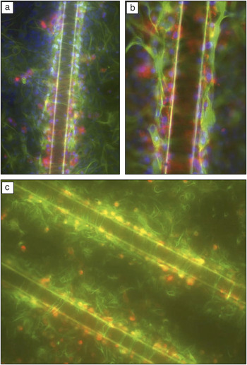
When injury occurs in the CNS, the astrocytes synthesize glial fibrillary acidic protein (GFAP), which adds to the projections and cytoskeletal structures of the astrocytes. After these activated astrocytes proliferate and accumulate at the injury site, they displace the nonregenerative CNS neurons and secrete matrix molecules that inhibit neural growth, thus leading to the formation of a glial scar. Currently, functionality of neural electrodes is limited by the response that results from chronic electrode implantation.Reference Turner, Shain, Szarowski, Andersen, Martins, Isaacson and Craighead23–Reference Kim, Hitchcock, Bridge and Tresco25 Managing the inflammatory response is critical for preserving neurons near the recording or stimulating sites during chronic implantation.Reference He, McConnell, Schneider and Bellamkonda26 An in vitro simulation of that inflammation response, shown in Figure 1, reveals the formation of a glial scar around a 50 μm diameter stainless steel microwire after 10 days of constant exposure to neural cell culture.Reference Polikov, Block, Fellous, Hong and Reichert27 Initial electrode insertion is injurious to multiple elements such as capillaries, ECM, and neural cells. This acute damage results in blood-borne macrophages entering through the vessels as well as activated astrocytes migrating toward the injury site.Reference Polikov, Tresco and Reichert28, Reference Griffith and Humphrey29 Reactive astrocytes have been shown to secrete ROS as well as a number of inflammatory cytokines, which can act as neurotoxins at high concentrations.Reference Block and Hong30, Reference Block, Zecca and Hong31 The eventual aggregation of astrocytes and other neural components constitutes an encapsulating sheath around the implanted electrode that grows in size for several weeks, after which the encapsulation layer becomes thinner and denser and stabilizes after ∼6 weeks.Reference Szarowski, Andersen, Retterer, Spence, Isaacson, Craighead, Turner and Shain24, Reference Silver and Miller32
(a–b) Fluorescent labeling with 4,6-diamidino-2-phenylindole (DAPI) staining the nuclei blue, glial fibrillary acidic protein (GFAP) staining reactive astrocytes green, and OX-42 staining microglia red. These images show the relative positions of different cells with respect to the microwire after 10 days in a neural cell culture. As observed in vivo, there is a layer of microglia (red) adjacent to the microwire, and astrocytes (green) outside of the microglial layer showing increased production of GFAP, indicative of tissue scarring. The image in (b) shows the glial scarring at a higher magnification, clearly showing the prevalence of microglia around the microwire. (c) Vimentin staining of astrocyte precursor cells that are being activated during scar formation (green) and OX-42 staining microglia red. The layer of microglia immediately next to the wire is surrounded by vimentin positive astrocyte processes forming the glial scar 10 days after wire placement. The wire diameter is 50 μm in all images. Reprinted with permission from Reference 27. ©2006, Elsevier.

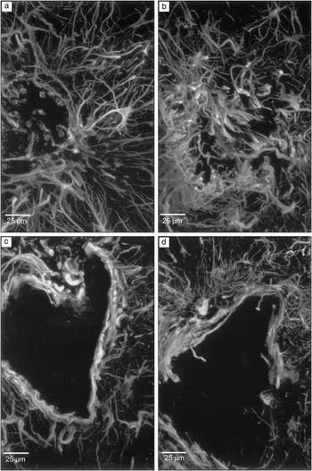
As shown in Figure 2, the integrity of in vivo glial encapsulation increases from 2 to 12 weeks of Si electrode exposure and subsequent removal.Reference Turner, Shain, Szarowski, Andersen, Martins, Isaacson and Craighead23 Consequently, over time, the glial scar results in displacement of the nearby neurons and reactive astrocytes that constitute the scar secrete inhibitory ECM molecules that hinder damaged axon regrowth.Reference Silver and Miller32 The arrested axon growth from nearby neurons indicates that the encapsulation prevents neurons from penetrating their projections through the glial sheath and accessing the recording site of electrodes.Reference Fawcett and Asher33, Reference Gilbert, McKeon, Darr, Calabro, Hascall and Bellamkonda34 These occurrences are indicated by an immediate and sustained increase of immunohistochemical markers specific for astrocytes as well as elevation in glial and astrocytes around the electrode for months after implantation.Reference Turner, Shain, Szarowski, Andersen, Martins, Isaacson and Craighead23, Reference Griffith and Humphrey29, Reference Fawcett and Asher33, Reference Griffith, Soria and Wood35 The glial scarring eventually leads to high impedance surrounding the electrode, resulting in a loss of electrode recording capability.Reference Haberler, Alesch, Mazal, Pilz, Jellinger, Pinter, Hainfellner and Budka14, Reference Turner, Shain, Szarowski, Andersen, Martins, Isaacson and Craighead23, Reference McConnell, Schneider, Owens and Bellamkonda36
Confocal microscope projection images of the insertion sites left by removing a silicon probe after 2, 4, 6, and 12 weeks of implantation (a–d, respectively). The samples are labeled with anti-GFAP (glial fibrillary acidic protein) antibodies to illustrate the reactive astrocytes. (a and b) After two and four weeks of implantation, the sheath structure collapsed on itself during probe removal; (c and d) after six and 12 weeks, the glial encapsulation had sufficient integrity to withstand the disruption from probe removal. Reprinted with permission from Reference 23. ©1999, Elsevier.

ECM-based material coatings lessen inflammatory responses
Coating the electrodes with ECM proteins and growth factors discourages glial scarring formation and improves neural cell adherence to the electrode. It has been demonstrated that coating the electrodes with adhesion proteins, or bioactive molecules, can alleviate the glial response.Reference Polikov, Tresco and Reichert28 Following the in vivo insertion of electrodes coated with adhesion proteins and growth factors, there was a decrease in the prevalence of glial scarring, as indicated by a reduction in the number of active microglia, indicated by the ED-1 (ectodermal dysplasia 1) staining and the number of reactive astrocytes, as shown by GFAP staining.Reference He, McConnell, Schneider and Bellamkonda26 A recent study also showed that cortical electrodes with laminin coatings resulted in intense ED-1 staining one day post-implant. However, at four weeks post-implant, there was a marked reduction in ED-1 staining and weakened GFAP intensity around the electrode tracts, indicating a decreased glial response compared to uncoated electrodes. Furthermore, chronically implanted Si microelectrode arrays coated with laminin layers on the order of nanometers thickness were shown to elicit decreased gliotic response after four weeks post-implant.Reference He, McConnell and Bellamkonda37 Along those lines, surface coatings of alpha melanocyte stimulating hormone, a potent anti-inflammatory peptide, have been shown to reduce inflammatory cytokines such as IL-1 and TNF-alpha and attenuate glial response in both in vitro cell culture and in vivo electrode implantation studies.Reference He, McConnell, Schneider and Bellamkonda26
Scaffolds
Another area of neural interface research lies in creating 2D and 3D scaffolds that guide neuron growth for signal propagation in neural networks and neural cell regeneration in depleted zones. ECM-based materials have been utilized for neural growth because comparable length scales promote adhesion and conformation. Furthermore, it has been shown that various ECM-based coatings help provide the biochemical cues that orient neuron growth along the desired pattern.
Adhesion and conformation due to characteristic length scale
Morphologies of neural cells are highly sensitive to their local environment, thus various substrate patterns have been used to modulate neural cell adhesion, spreading, and growth. The dimensions of patterned lines and islands have been shown to control the migration and spreading of both neurons and glial cells. Neural growth cones, the growing ends of developing axons that sense the surroundings for a target neuron to form synapses with, are attuned to physical topography even in the absence of specific biochemical cues. This unique feature can enable directional growth of neural cells, particularly on ECM materials, since both neural growth cones and ECM proteins have characteristic lengths within the nanometer range.Reference Dalby, Gadegaard, Riehle, Wilkinson and Curtis38, Reference Nurcombe, Aumailley, Timpl and Edgar39
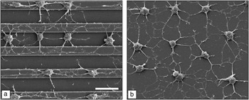
A study using adult rat hippocampal progenitor cells (Figure 3), stem cells from the region of the brain that processes memory and spatial navigation, demonstrated that those that exhibited neuronal morphologies had axons extended in axial alignment with the grooves of a patterned substrate coated with laminin.Reference Recknor, Sakaguchi and Mallapragada40 Axons of peripheral neurons experience guiding effects when lateral features are around 100 nm.Reference Abrams, Goodman, Nealey, Franco and Murphy12 A recent study showed that selectively patterned laminin on both photolithographically patterned substrates and microchannels embedded in PDMS improved neural attachment and extension in in vitro studies.Reference Dertinger, Jiang, Li, Murthy and Whitesides41, Reference Thompson and Buettner42 In addition, patterned coatings of laminin on silicon have been shown to promote attachment and differentiation of cortical cell cultures.Reference He and Bellamkonda43 These findings suggest that nanoscale precision of ECM protein coatings on devices would be valuable for integration. The ability for tissue to interface with the device on the protein level could lead to an improvement in signal quality and information exchange between the two entities.
Scanning electron microscopy images of adult rat hippocampal progenitor cells (AHPCs) cultured on a poly-L-lysine (PLL) and laminin coated polystyrene substrate. (a) AHPC projections were aligned with the grooves on the micropatterned substrate. (b) AHPC projections were oriented randomly on the non-patterned side of the substrate. Images were taken from cultures at seven days after plating. Scale bar = 30 μm. Reprinted with permission from Reference 40. ©2006, Elsevier.

Furthermore, a greater degree of fit between a device and neurons on the molecular length scale can improve surface contact and reinforce their interaction.Reference Kotov, Winter, Clements, Jan, Timko, Campidelli, Pathak, Mazzatenta, Lieber and Prato20 Interfacing devices with peripheral nerves is challenging in terms of conforming a rigid device around the nerve cables, which are 3D structures with individual fibers connecting and signaling for distinct motor and sensory information. The preferable choice would be a device made from a flexible material that can fit to the peripheral nerves on the cellular level so that there will be more selective signal transfer between the device and the nerve fibers.Reference Grill, Norman and Bellamkonda44
ECM materials as coatings for neural guidance
Specific and directional formations of neural networks have a wide range of applications, including the development of assays,Reference Hung, Lee, Sabounchi, Lin and Lee45 biosensors, and synthetic networks.Reference Chang, Brewer and Wheeler46 Isolated small neural networks grown on laminin-patterned substrates have been developed to examine the signaling interactions between neurons in such networks, including how they sense and respond to their microenvironment.Reference Kuhn, Schmidt and Kater47 Moreover, microfluidic architectures can be constructed for in vitro assessment of neural network behavior on surfaces modified with ECM molecules.Reference Reyes, Perruccio, Becerra, Locascio and Gaitan48, Reference Mehenti, Fishman and Bent49 Since microfluidic channels can create biochemical gradients along various axes in 2D or 3D, they comprise a feasible means of studying the directional response of neuron stimulation.Reference Mehenti, Fishman and Bent49–Reference Rowe, Almasri, Lee, Fogleman, Brewer, Nam, Wheeler, Vukasinovic, Glezer and Frazier51
One study has shown that when a monolayer of regenerating neurons was cultured on a monolayer of aligned astrocytes, they grew in parallel with the astrocytes and expressed aligned linear arrays of matrix proteins. These findings suggest that by manipulating the orientation of astrocytes in an engineered scaffold, it is possible to facilitate neural regeneration.Reference Biran, Noble and Tresco52 For instance, conductive polymer coatings with localized doping of neural growth factor and ECM proteins at electrode sites minimize tissue reaction and promote neural growth and adhesion.Reference Kim, Richardson-Burns, Hendricks, Sequera and Martin53–Reference Cui, Wiler, Dzaman, Altschuler and Martin55 Such guidance allowed peripheral nerves to interface with regenerating axons from amputated nerve stumps.Reference Kim, Haftel, Kumar and Bellamkonda56 Anisotropic patterning of growth factors and ECM proteins can guide axons,Reference Dodla and Bellamkonda57, Reference Luo and Shoichet58 which would enhance peripheral nerve implant stability and positively impact the signal to noise ratio through the close proximity of neurons to electrodes. As with neural electrode arrays, microfabrication technology such as microcontact printingReference Craighead, Turner, Davis, James, Perez, St. John, Isaacson, Kam, Shain, Turner and Banker59, Reference Wojciak-Stothard, Denyer, Mishra and Brown60 can also be applied to pattern ECM proteinsReference Zhang, Stilwell, Gerion, Ding, Elboudwarej, Cooke, Gray, Alivisatos and Chen61, Reference Wyart, Ybert, Bourdieu, Herr, Prinz and Chatenay62 such as laminin,Reference Kam, Shain, Turner and Bizios63 fibronectin,Reference Parker, Brock, Brangwynne, Mannix, Wang, Ostuni, Geisse, Adams, Whitesides and Ingber64 and collagenReference Rohr, Flückiger-Labrada and Kucera65 with nano- and microscale precision to allow directional guidance of neuron growth.
ECM materials for scaffolds
ECM materials used for tissue engineering include collagen, fibrin, fibronectin, and hyaluronic acid (HA).Reference Willerth and Sakiyama-Elbert66 Collagen is currently used as a gel scaffold by modulating its pH and concentration. Neural cells can be tethered to the gel through various adhesion sites. The disadvantage of collagen is potential cross-species immune response.Reference Archibald, Krarup, Shefner, Li and Madison67–Reference Wissink, Beernink, Pieper, Poot, Engbers, Beugeling, Van Aken and Feijen69 Fibrin is currently used as a sealant for wound healing with properties that can be modified by modulating the concentration or with chemical modification to alter its properties.Reference Herbert, Bittner and Hubbell70, Reference Sakiyama-Elbert and Hubbell71 Fibronectin is a glycoprotein also used in wound healing but can be used to bind collagen, fibrin, and heparin. The aggregate form of fibronectin is a mat, containing aligned pores that promote neural guidance during regeneration, absorb growth factors, and bond to cells.Reference King, Henseler, Brown and Priestley72–Reference Brown, Blunn and Ejim74 HA is a glycosaminoglycan found in ECM that does not provoke an immune response in the body. The disadvantage with working with HA is that it is water soluble so it needs to be incorporated with other elements before application.Reference Gupta, Tator and Shoichet75
ECM and synthetic composite scaffolds for neural regeneration
Bioactive and biocompatible peptide-based self-assembling nanofibers that form scaffold materials are being developed for tissue engineering for neural regeneration applications.Reference Hartgerink, Beniash and Stupp76–Reference Silva, Czeisler, Niece, Beniash, Harrington, Kessler and Stupp78 They can emulate both the mechanical and biochemical properties of the ECM environment. One group has demonstrated that culturing neural progenitor cells within a 3D network of self-assembled peptide nanofibers with integrated laminin epitope can induce rapid differentiation of the progenitor cells while suppressing the development of astrocytes.Reference Silva, Czeisler, Niece, Beniash, Harrington, Kessler and Stupp78 Another study has shown that neurons can grow into monolayers when cultured on top of vertically aligned carbon nanofiber array scaffolds coated with polypyrrole (for preserving the vertical alignment of the nanofibers) and collagen. This investigation suggests the potential for nanoscale electrical-neural interface that could lead to opportunities for deep brain stimulation given the high aspect ratio of the carbon nanofibers.Reference Nguyen-Vu, Chen, Cassell, Andrews, Meyyappan and Li79
Because neurons are dependent on topographical cues from the scaffold for growth and cellular communication, aligned polymer nanofiber constructs have proven to induce more regeneration compared to amorphous ones based on electrophysiological and behavioral analyses.Reference Kim, Haftel, Kumar and Bellamkonda56 Recent microfabrication techniques using lithography and molding have also been developed for synthesizing ribbon-like collagen microfiber structures that are embedded in an elastin protein matrix to generate multi-tiered fiber-reinforced composite materials. Mechanical testing has shown that this structure has a mechanical response that is comparable to that of native tissue.Reference Caves, Kumar, Xu, Naik, Allen and Chaikof80–Reference Naik, Caves, Kumar, Chaikof and Allen82 Together these findings strongly indicate that this type of biomimetic composite structure has very promising prospects in future neural tissue engineering applications.
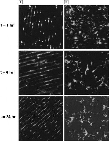
In addition to aligned fibers, studies have shown that ECM molecules secreted from aligned neural supporting cells combined with cell-matrix adhesion factors can further guide the growth of neurons. Longitudinally oriented glial cells stimulate and support the parallel growth of axons and neurons by releasing aligned and constrained pathways of ECM molecules as biochemical cues.Reference Biran, Noble and Tresco52 Other cells that have been shown to successfully orient the propagation of neurons and their projections include fibroblasts (cells that synthesize matrix proteins), meningeal cells (cells that aid in the development of a physical barrier between CNS and foreign entities), astrocytes, and Schwann cells oriented on substrates with topographically aligned features (Figure 4).Reference Thompson and Buettner42, Reference Biran, Noble and Tresco52, Reference Kim, Richardson-Burns, Hendricks, Sequera and Martin53, Reference Miller, Jeftinija and Mallapragada83–Reference Walsh, Manwaring and Tresco85
Schwann cell response to micropatterned and unpatterned laminin substrates at 1, 6, and 24 hours after plating. (a) Schwann cells aligned with the micropattern as early as one hour after plating. (b) Schwann cells on unpatterned laminin surfaces did not exhibit a preferred orientation. The width of each micrograph is 640 μm. Reprinted with permission from Reference 42. ©2001, Mary Ann Liebert, Inc.

Furthermore, constructs that incorporate ECM material and CNTs have been demonstrated to promote neural stem cell (NSC) differentiation and proliferation. NSCs are multipotent stem cells that can differentiate into neurons and glial cells. Cell-seeded 3D protein materials doped with CNTs can create a directionally conductive cellular matrix.Reference MacDonald, Voge, Kariolis and Stegemann86, Reference Voge, Kariolis, MacDonald and Stegemann87 Laminin coated single wall carbon nanotube (SWNT) films support the growth and proliferation of NSC, along with the formation of synapses.Reference Kam, Jan and Kotov88 Another study showed that cultured human embryo stem cells (ESCs) on surfaces of roughly aligned collagen-SWNT composite material exhibit significantly higher levels of nestin expression, an intermediate filament in neural cells, than on collagen or gelatin substrate alone.Reference Sridharan, Kim and Wang89 An increased degree of ESC differentiation was attributed to the morphological changes induced by adding SWNT to the collagen film, further demonstrating that the combination of ECM and CNTs is more favorable to the differentiation of stem cells into neurons than ECM alone.
ECM-based drugs embedded in scaffolds
Scaffolds can also be used to deliver ECM-based drugs. One major type of therapeutic used for neural tissue engineering is neurotrophin, a growth factor that plays an important role in activating signaling pathways, modulating cell apoptosis (cell death), and promoting neurogenesis.Reference Wiesmann and De Vos90, Reference Grill, Murai, Blesch, Gage and Tuszynski91 Other growth factors include ones that promote regeneration such as ciliary neurotrophic factor, fibroblast growth factors, transforming growth factor β, and glial derived neurotrophic factor.Reference Willerth and Sakiyama-Elbert66 They promote regeneration by inducing blood vessel growth to injury sites, promoting neural cell proliferation, and reducing reactive astrocyte proliferation. Drugs can be delivered into the system either by degradation of the scaffold or diffusion. To regulate the rate and dosage of drug release, the scaffold porosity and density are modulated by varying the ratio between drug and scaffold material during fabrication.Reference Willerth and Sakiyama-Elbert66
Nanoparticles
NPs are currently being explored for both neural imaging and drug delivery because they are able to penetrate the blood brain barrier and are especially useful for tracking individual neurons. For dynamic imaging of neural activity using MRI or fluorescence microscopy, it is important to have high contrast agents that react on a time scale comparable to that of the membrane activation potential of neurons.Reference Peleg, Lewis, Linial and Loew92–Reference Nadeau, Clarke, Hollmann and Bahcheli96 Magnetic NPs are attractive candidates for imaging that can also be conjugated with peptides and antibodies for use in diagnostics and therapeutic treatment.Reference Jun, Seo and Cheon97, Reference Jordan and Maier-Hauff98 Quantum dots, which are semiconductor NPs, have specific and narrow emission spectra upon excitation by broad spectra in the UV range. With biochemically functionalized surfaces, quantum dots are used to track and label neurons and astrocytesReference Maysinger, Behrendt, Lalancette-Hébert and Kriz99, Reference Pathak, Cao, Davidson, Jin and Silva100 as well as to probe the diffusion of individual neurotransmitter receptorsReference Dahan, Levi, Luccardini, Rostaing, Riveau and Triller101, Reference Zuber, Nikonenko, Klauser, Muller and Dubochet102 and visualize their intricate molecular interactions. Coating quantum dot surfaces with antibody allows them to interact with cell surfaces by recognizing and targeting cells that have a corresponding acceptor surface proteins.Reference Derfus, Chan and Bhatia103 Nanocolloids are employed in neural applications as drug delivery vessels or contrast agents for imaging since they can penetrate the blood brain barrier and accumulate in certain areas of the brain. The drugs delivered are anti-inflammatory agents, neural growth factors, and gene therapy.Reference Xie, Ye, Zhang, Cui, Lou, Nagai and Hou104
The main concern in these applications is the potential toxicity of the NPs. Other issues include absorption of NPs by the body and removal of the particles after they have completed their functions. By encapsulating these NPs with a layer of ECM-based material, toxicity to the neurons may be shielded and NPs can tether to target receptors if they need to be in the body for a period of time. NPs in the nervous system pass through the olfactory bulb, the region in brain for odor perception, and migrate to other parts through neurons and by crossing synapsesReference Oberdörster, Oberdörster and Oberdörster105, Reference Oberdörster106 Some of the current NPs consist of metals such as Ag and Au, and metal oxides such as Fe3O4, Fe2O3, and SiO2. Other NPs use Cd containing semiconductor materials, liposomes, lipids, and biodegradable polymers. The toxicity of the semiconductor and organic NPs is a complex topic because it is dependent on factors such as size of the NPs, the site of accumulation, and the constituent materials.Reference Fernández-Urrusuno, Fattal, Féger, Couvreur and Thérond107–Reference Chan, Shiao and Lu113
Many studies use ROS generation and mitochondria interference to characterize NP cytotoxicity across different materials and different types of cells.Reference Fischer and Chan114, Reference Díaz, Sánchez-Espinel, Arruebo, Faro, de Miguel, Magadán, Yagüe, Fernández-Pacheco, Ibarra and Santamaría115 As mentioned before, ROS results in oxidative stress, cell respiration reduction, an increase in permeability of the cell membrane, and a damaged nucleus; all contributing to eventual apoptosis.Reference Chan, Shiao and Lu113, Reference Lovric, Cho, Winnik and Maysinger116 Nanotoxicity also can be indicated by reactive astrocytes, whose signature is GFAP expression in the cell membrane. Cd containing semiconductor NPs can alter neural cell morphology, increase lipid peroxidation, and reduce metabolic activity, resulting in eventual apoptosis.Reference Chan, Shiao and Lu113, Reference Choi, Cho, Desbarats, Lovrić and Maysinger117 Since the particles carry the potential for toxicity with them as they migrate, it is important to determine the particle distribution within the nervous system and ensure their stability.
Layer-by-layer assembled collagen films encapsulating CdTe NPs provide partial protection to the neural cells.Reference Sinani, Koktysh, Yun, Matts, Pappas, Motamedi, Thomas and Kotov118 Cd alone is a notable neural toxin and carcinogen that interferes with DNA repair as well as zinc metabolic pathways in the liver and kidney.Reference Waalkes119, Reference Hartwig and Schwerdtle120 Nevertheless, shielding with even a thin layer of collagen coating significantly reduces the toxicity effect because the contact area between the Cd NP core and neural cells is reduced.
Conclusion
This review highlights three categories of neural interfacing that can benefit from using extracellular matrix (ECM) materials. These are neural electrodes for stimulating and recording, scaffolds for neural regeneration using neural guidance and drug delivery, and using nanoparticles (NPs) for imaging and drug delivery. For neural electrodes, the major concern is inflammation due to chronic implantation. Inflammation is present as a glial scar that encapsulates the electrodes leading to neuron displacement, impedance increase, and ultimately device failure. ECM materials can mitigate an inflammatory response because they are biocompatible and biodegradable in addition to being less foreign.
ECM materials can also be utilized in constructing scaffolds for neural guidance, tissue engineering, and drug delivery. Neural cells are very sensitive to the characteristic length scale of the features of the surface topography because it determines the orientation of their proliferation and extension of cell projections. Polymer scaffolds and other materials can be fabricated with these dimensions, but they still should incorporate ECM-based materials to promote cell adhesion and provide biochemical cues to guide the cells. ECM materials naturally have the characteristic length scales that comprise the optimal cell conditions.
For drug delivery, ECM-based materials have been utilized both as a drug in the form of neural growth factors and an anti-inflammatory as well as a drug delivery vehicle in the form of a scaffold. NPs are effective tools for drug delivery and imaging because they can easily permeate into regions of the nervous system and penetrate through the blood brain barrier. However, toxicity is a concern for many forms of NPs. In that respect, ECM-based materials may provide coatings that reduce the toxicity of these particles.
Along with the many benefits, there are some limitations of ECM-based materials. Many ECM proteins can be difficult and expensive to isolate and reconstitute into natural proteins for use in a cell culture. Given the small quantity and large number of steps involved in these processes, there may be inconsistency in concentration from batch to batch. Overall, ECM-based materials are very promising in the functionalities that they can deliver and the solutions they can provide to targeted applications.