1. Introduction
Up to now, many mechanisms have been designed and applied. In this aspect, Li et al. synthesized a family of 3 degrees of freedom (DOF) parallel leg mechanisms with a 3-DOF drive system and a walking mechanism [Reference Li, Fang, J.Q. and Wang1]. Shi et al. proposed a method involving conceptual configuration synthesis and topology structure analysis to obtain a series of double-layer deployable hoop antenna units [Reference Shi, Guo, Zheng, Li, Liu and Deng2]. Chi et al. developed a compliant gripper with parallel gripping motion using the topology synthesis approach [Reference Chi, Teeranoot and Wang3]. Chinvorarat et al. presented a retractable main landing gear for a light amphibious airplane and conducted its synthesis and analysis [Reference Chinvorarat and Vallikul4]. Based on graph theory, Sun et al. introduced a swinging linkage mechanism into the transplanting mechanism to overcome the limitation of traditional gear train transplanting mechanisms [Reference Sun, Zhou, Chen, Wu and Zhang5]. Parlaktas studied a synthesis method for a geared adjustable stroke mechanism [Reference Parlaktaş6]. Yang and Jin [Reference Yang7] studied the topology structure design of robot mechanisms. Gogu [Reference Gogu8] conducted structural synthesis of parallel robots using morphological and evolutionary approaches. Huang et al. proposed a theory of loop algebra of multi-loop kinematic chains and improved the Kutzbach–Grübler formula of mechanism DOF by considering redundant constraint and passive DOF [Reference Huang, Li and Ding9]. Kong et al. studied the topological synthesis and type synthesis of parallel mechanisms based on screw theory [Reference Kong and Gosselin10]. Wang et al. synthesized a family of (3 translations and 2 rotations plus grasping motion) gripper mechanisms based on generalized parallel mechanisms with a configurable moving platform [Reference Wang, Fang and Li11]. Let (l 2, l 3, l 4, l 5, l 6) be (binary, ternary, quaternary, pentagonal, and hexagonal) links, respectively. In the aspect of the creation of a mechanism, Johnson [Reference Johnson12] represented variable kinematic pairs using several l 2 and 1-DOF joints. Lu et al. [Reference Lu, Ye and Zhang13] determined the complexity coefficient of closed mechanisms based on the number of l j (3 ≤ j) in the complexity mechanism and solved the number of l 2 based on the improved Kutzbach–Grübler DOF formula. Xia et al. [Reference Xia, Tian and Zhang14] developed the continuous origami mechanisms based on topology graph TG theory and the synthesis approach. Above studies provide the theoretical foundations for designing various complex mechanisms. Generally, various complex mechanisms may have more mechanical advantages and more functions, such as enlarging output power, increasing (structure strength, rigidity, stability, shifting distance, speed reduction ratio, output torque, DOF, workspace), reducing (energy consumption, gear meshing load, weight, machine size, vibration), and so on. Therefore, it has been a significant and challenging issue to create more novel mechanisms with more mechanical advantages and useful functions, such as adjusting the plate mechanism of airplane nozzle, airplane vector nozzle, landing mechanism of airplane, helicopter rotor, speed reducer of helicopter, forge operator with multi-jaw, robot hand with multi-finger, folding antenna, artificial heart, flexible airfoil, long-stroke pumping unit, and excavator of tunnel.
Let C n(k)i represent a digit topology circle with n (l 3, l 4, l 5, l 6, …) and excluding l 2. Several subscripts (n, j, k, i) of C n(k)i are explained as follows: n is the number of links l j (j = 3, 4, 5, 6, …), each of l j is represented by a dot; j is the adjacent number of l j ; k is the maximum value of j; i is the order number of C n(k)i , (i = 1, 2, …). For instance, C 6(5)3 includes (1l 5, 2l 4, 3l 3); here, n = 1 + 2 + 3 = 6, k = maximum{5, 4, 3} = 5, i = 3. Since C n(k)i excluding l 2 can be represented using a circle, fewer lines and arcs, various C n(k)i must be simpler than the topology graph TG including link l j (j = 2, 3, 4, 5, 6, …), and the derivation and isomorphism identification of C n(k)i must be easier than that of TG. For this reason, C n(k)i are proposed for designing novel closed mechanisms in this paper. Therefore, it is a significant and challenging issue to derive various C n(k)i and to create the novel mechanism with more mechanical advantages and more functions using derived C n(k)i . For this reason, several studies in this paper are conducted as follows:
(1) Discover the derivation rules of C n(k)i . (2) Construct simple C n(k)i (n = 3,…, 6) with n (l 3, l 4). (3) Derive complex C n(k)i (n = 3,…, 6) with n (l 3, l 4, l 5, l 6, …) from the simple C n(k)i . (4) Develop the creation approach of the novel mechanisms using C n(k)i .
2. Conceptions and relations among digit topology circle C n(k)i , topology graph, and mechanism
The relative symbols and formulas are explained as below,
(l 2, l 3, l 4, l 5, l 6) = (binary, ternary, quaternary, pentagonal, hexagonal) link;
TG = topology graph, e = edge (single curve) in TG; l j = link represented by dot adjacent j e;
n lj = the number of l j ; DOF = degree of freedom;
C n(k)i = digit topology circle excluding l 2; C n(k)0i = open-digit topology circle excluding l 2;
n = the number of (l 3, l 4, l 5, l 6, …) in C n(k)i , n = ∑n lj ; k = the maximum value of j;
i = the number of C n(k)i , (i = 1, 2, …); n e = the number of edges in C n(k)i , n e = ∑(jn lj )/2;
S, U, C, P , P, R, S c = (spherical, universal, cylinder, active prismatic, prismatic, revolute, and screw) joint.
A closed mechanism may include several links connected by several kinematic pairs. For instance, a 2SPU/UPU/SP type parallel mechanism is composed of a base B, a moving platform m with a central cylinder, 2 SPU linear limbs with an active P joint, a UPU linear limb with an active P joint, and a central SP linear limb with a P joint. Two ends of each SPU limb connect with B and m by S and U joints, respectively. Two ends of the UPU limb connect with B and m by 2U joints, respectively. Two ends of the SP limb connect with B and m by S and P joints; see Figure 1(a). Here, both B and m are l 4, and the bold symbol represents an active joint.
Relation among mechanism, topology graph, and digit topology circles. (a) 2SPU/UPU/SP mechanism, (b) TG of closed mechanism with 4e, (c) three C2(4)i (i = 1, 2, 3).

Figure 1 Long description
Panel A: A diagram of a 2SPU/UPU/SP mechanism. It shows a three-dimensional structure with various labeled points and lines, including U, P, S, B, m, and l2. Panel B: A topology graph of a closed mechanism with 4 edges (4e). It depicts a three-dimensional structure with points and lines labeled U, P, S, B, m, and l2. Panel C: Three digit topology circles labeled C2(4)1, C2(4)2, and C2(4)3. Each circle contains points labeled 0, 1, 2, and 3, connected by lines labeled l4.
Generally, a TG is more complex because it may include several links l j (j = 3, 4, 5, 6, …) and some l 2 for representing various kinematic pairs. It is known that 2l 2 connected serially by 3 one-DOF joints can be used to replace 1S joint; 1l 2 connected serially by 2 one-DOF joints can be used to replace 1U or 1C joint; one-DOF joint can be used to replace 1P or 1R or 1S c joint [Reference Johnson12, Reference Lu, Ye and Zhang13]. Since the 2SPU/UPU/SP type parallel mechanism includes 2l 4, 3S joints, 4U joints, and 4P joints, it can be represented by a TG with 2l 4 and 17l 2 connected by 21 one-DOF joints; see Figure 1(b). Each one-DOF joint can be represented by a dot. TG in Figure 1(b) can be represented by one of the simple C 2(4)i (i = 1, 2, 3); see Figure 1(c). It is known from Figure 1(c) that (1, 2, 1) in C 2(4)1, (2, 0, 2) in C 2(4)2, and (1, 0, 3) in C 2(4)3 represent the number (n e = 4) of three group parallel edges for connecting 2 dots l 4. Therefore, when the digits ≥1 marked on the arc of C 2(4)i (i = 1, 2, 3) are satisfied, three C 2(4)i (i = 1, 2, 3) with (n e = 4, 2l 3) represent all possible configurations for C 2(4)i with (n e = 4, 2l 3). Obviously, C n(k)i is simpler than TG.
3. Construction of simple C n(k)i and their structure
When n is an odd number, the simple C n(k)i includes 1l 4 and (n−1)l 3; l 4 is located at the upper dot. When n is an even number, the simple C n(k)i includes n l 3. Based on this rule, 16 simple C n(k)i are constructed; see Figure 2.
Several simple Cn(k)i with {l3, l4, (n = 2, …, 6)} and 3 open Cn(k)0i with {l3, l4, l6, (n = 3, 4)}.

C n(k)i (n = 3, 4, …) excluding l 2 is formed by a circle, n dots on the circle, and several lines and n arcs. Each line or arc may be formed by a group of parallel edges for connecting two dots. The digit marked onto a line or an arc is the number of parallel edges. Generally, when C n(k)i includes fewer dots and l j with fewer adjacent numbers, it can be constructed more easily. Here, two isomerism simple C 2(3)i (i = 1, 2) with (n = 2, 2l 3) are constructed; see Figure 2(a1, a2). One simple C 3(4)1 with (n = 3, 1l 4, 2l 3) is constructed; see Figure 2(a3). Two isomerism simple C 4(3)i (i = 1, 2) with (n = 4, 4l 3) are constructed; see Figure 2(a5, a6). Four isomerism simple C 5(4)i (i = 1, …, 4) with (n = 5, 1l 4, 4l 3) are constructed; see Figure 2(a9–a12). Four isomerism simple C 6(3)i (i = 1, …, 4) with (n = 6, 6l 3) are constructed; see Figure 2(a13–a16). For instance, the simple C 5(4)3 includes a circle, n = 5 dots for representing (1l 4, 4l 3), 3 lines, n = 5 arcs, and 2 grey dotted lines. Here, l k (k = 4) is located on the up dot; each of the 3 lines is marked by the digit 1; 5 arcs are marked by the digits (1, 1, 1, 1, 1), respectively, and each of the 2 dotted lines is marked by the digit 0. Thus, C 5(4)3 has k = maximum {3, 4} = 4, n l3 = 4, n l4 = 1, n = n l3 + n l4 = 5, n e = ∑(jn lj )/2 = (3 × 4 + 4 × 1)/2 = 8. All dotted lines and all digits 0 in C n(k)i can be deleted from C n(k)i .
Since the digits ≥ 1 are marked on the arc of C 2(3)i (i = 1, 2) with (n = 2, n e = 3, 2l 3), C 2(3)1 and C 2(3)2 are mutually isomorphic and represent all possible configurations for C 2(3)i with (n = 2, n e = 3, 2l 3). Since three C 2(4)i (i = 1, 2, 3) are derived from C 2(3)i (i = 1, 2), C 2(4)i (i = 1, 2, 3) must be mutually isomorphic, and represent all possible configurations for C 2(4)i with (n = 2, n e = 4, 2l 4). Since the digits ≥ 1 are marked on arc of C 5(4)i (i = 1, …, 4) with (n = 5, 1l 4, 4l 3) and C 6(3)i (i = 1, …, 4) with (n = 6, 6l 3) in Figure 2, four C 5(4)i (i = 1, …, 4) with (n = 5, n e = 8, 1l 4, 4l 3) represent all possible configurations for C 5(4)i with (n = 5, n e = 8, 1l 4, 4l 3); four C 6(3)i (i = 1, …, 4) with (n = 6, n e = 9, 6l 3) represent all possible configurations for C 6(3)i with (n = 6, n e = 9, 6l 3).
When a digit 0 is marked on the arc of C n(k)i , it is named as an open-digit topology circle and is represented by C n(k)0i . Three simple open C 3(6)01 with (1l 6, 2l 3) and C 4(4)0i (i = 1, 2) with (2l 3, 2l 4) are constructed; see Figure 2(a4, a7, a8). It is known that when a digit 0 is marked on a different arc of C n(k)i , the different open C n(k)i can be derived. Therefore, C 3(6)01 with (1l 6, 2l 3) does not represent all possible configurations for C 3(6)0i . Similarly, C 4(4)0i (i = 1, 2) with (2l 3, 2l 4) does not represent all possible configurations for C 4(4)0i .
4. Derivation of complex digit topology circles from simple digit topology circles
When increasing the number of dots n or the maximum value k of j (the adjacent number of link l j ) of C n(k)i , C n(k)i must become a complex one. When n = (2, 3), the number of C n(k)i is less, and their derivation must be easy. When 4 ≤ n, the number of C n(k)i must be increased greatly.
Using the digit +1 approach, many complex C n(k + 1)i or C n(k)i with more l k can be derived gradually from simple C n(k)i with less l k . The derivation processes are explained as follows:
-
1. Increase one of the line or arc digits in C n(k)i by 1. Here, the digits include the digit marked on the line or arc and the subscripts of two links l j (3 ≤ j ≤ k) connected with a line or arc in C n(k)i ;
-
2. Change the revised line or arc digits in C n(k + 1)i or C n(k)i with more l k into grey digits, and add an arrow from C n(k)i with less l k to C n(k + 1)i or C n(k)i with more l k .
-
3. Repeat the above steps (1, 2) until all l j (3 ≤ j ≤ k) in C n(k)i are changed into l k + 1.
In some cases, using the digit−1 approach, new C n(k)i can be derived from existing C n(k)i as follows:
-
1. Reduce one of the line or arc digits in existing C n(k)i by 1. The digits include 1≤ digit marked on line or arc and the subscripts of two links l j (4 ≤ j ≤ k) connected with line or arc in existing C n(k)i ;
-
2. Change the revised digits in new C n(k)i into grey digits, and add an arrow with “-1” from existing C n(k)i to new C n(k)i .
Let C b and C a be two different digit topology circles. If C b can be derived from C a using the digit + 1 approach, C a is simpler than C b . If C b can be derived from C a using the digit -1 approach, C b is simpler than C a . In order to simplify the explanation, some symbols are used to represent the line or arc positions in C n(k)i as follows:
| = vertical line, ― = horizontal line, /↑ = left-up oblique line, /↓ = left-low oblique line, \↑ = right-up oblique line, \↓ = right-low oblique line, ―↑ = up horizontal line, ―↓ = low horizontal line, ∪ = low arc, ) = right arc, ⎞ = right-up arc, ⎠ = right-low arc, (= left arc, ⎛ = left-up arc, ⎝ = left-low arc.
Using the digit +1 approach, C 2(4)1 in Figure 1(c) can be derived from C 2(3)2 in Figure 2(a2) by changing ⎜ marked by digit {l 3, 1, l 3} of C 2(3)2 into ⎜ marked by digit {l 4, 2, l 4} of C 2(4)1. Here, “marked by digit” between the symbol and {digit } can be omitted in all text. Using the digit + 1 approach, C 2(4)2 and C 2(4)3 in Figure 1(c) can be derived from C 2(3)1 in Figure 2(a1) by changing ({l 3, 1, l 3} and) {l 3, 2, l 3} of C 2(3)1 in Figure 2(a1) into ({l 4, 2, l 4} and) {l 4, 3, l 4} of C 2(4)1, respectively.
4.1 Derivation of C3(k)i
Using the digit + 1 approach, some C 3(k)i with (n = 3, 3 ≤ k ≤ 10) are derived from C 3(4)1 with (1l 4, 2l 3) in Figure 2(a3). The derivation arrows and processes are shown in Figure 3 and are explained as follows:
-
1. C 3(5)i (i = 1, 2) with l j ( 3≤ j ≤ 5) are derived from C 3(4)i (i = 1, 2) by changing ⎞ {(l 4, 2, l 3), (l 4, 2, l 4)} of C 3(4)i (i = 1, 2) into ⎞ {(l 5, 3, l 4), (l 5, 3, l 5)} of C 3(5)i (i = 1, 2), respectively.
-
2. C 3(6)i (i = 2, 3) with l j (3 ≤ j ≤ 6) are derived from C 3(5)1 by changing {⎞ (l 5, 3, l 4), ⎛ (l 5, 2, l 3)} of C 3(5)1 into {⎞ (l 6, 4, l 5), ⎛ (l 6, 3, l 4)} of C 3(6)i (i = 2, 3), respectively.
-
3. C 3(6)1 with (2l 6, 1l 4) is derived from C 3(6)2 by changing ∪ (l 3, 1, l 5) of C 3(6)2 into ∪ (l 4, 2, l 6) of C 3(6)1.
-
4. C 3(6)5 with (1l 6, 2l 5) is derived from C 3(5)2 with (2l 5, 1l 4) by changing ⎛ (l 5, 2, l 4) of C 3(5)2 into ⎛ (l 6, 3, l 5) of C 3(6)5.
-
5. C 3(6)4 with 3l 6 is derived from C 3(6)5 by changing ∪ (l 5, 2, l 5) of C 3(6)5 into ∪ (l 6, 3, l 6)} of C 3(6)4.
-
6. C 3(7)i (i = 1, …, 5) with l j (3 ≤ j ≤ 7) are derived from C 3(6)i (i = 1, …, 5) with l j (3 ≤ j ≤ 6) by changing ⎞ {(l 6, 4, l 6), (l 6, 4, l 5), (l 6, 3, l 4), (l 6, 3, l 6), (l 6, 3, l 5) } of C 3(6)i (i = 1, …, 5) into ⎞ {(l 7, 5, l 7), (l 7, 5, l 6), (l 7, 4, l 5), (l 7, 4, l 7), (l 7, 4, l 6)} of C 3(7)i (i = 1, …, 5), respectively.
-
7. C 3(8)i (i = 1, 2, 5) with (l j , 3 ≤ j ≤ 8) are derived from C 3(7)i (i = 1, 2, 4) with (l j , 3 ≤ j ≤ 7) by changing ⎞ {(l 7, 5, l 7), (l 7, 5, l 6), (l 7, 4, l 7)} of C 3(7)i (i = 1, 2, 5) into ⎞ {(l 8, 6, l 8), (l 8, 6, l 7), (l 8, 5, l 8)} of C 3(8)i (i = 1, 2, 5), respectively.
-
8. C 3(8)i (i = 3, 4) with (l j , 4 ≤ j ≤ 8) are derived from C 3(7)3 with (l j , 4 ≤ j ≤ 7) by changing {⎞ (l 7, 4, l 5), ⎛ (l 7, 3, l 4)} of C 3(7)3 into {⎞ (l 8, 5, l 6), ⎛ (l 8, 4, l 5)} of C 3(8)i (i = 3,4), respectively.
-
9. C 3(8)i (i = 6,7) with l j (5 ≤ j ≤ 8) are derived from C 3(7)5 with (l j , 5 ≤ j ≤ 7) by changing {⎞ (l 7, 4, l 6), ⎛ (l 7, 3, l 5)} of C 3(7)5 into {⎞ (l 8, 5, l 7), ⎛ (l 8, 4, l 6)} of C 3(8)i (i = 6, 7), respectively.
-
10. C 3(8)8 with (1l 8, 2l 7) is derived from C 3(8)7 with (1l 8, 2l 6) by changing ∪ (l 6, 2, l 6) of C 3(8)7 into ∪ (l 7, 3, l 7) of C 3(8)8.
-
11. C 3(8)9 with 3l 8 is derived from C 3(8)8 by changing ∪ (l 7, 3, l 7) of C 3(8)8 into ∪ (l 8, 4, l 8) of C 3(8)9.
-
12. C 3(9)i (i = 1, … , 9) are derived from C 3(8)i (i = 1, … , 9) by changing ⎞ {(l 8, 6, l 8), (l 8, 6, l 7), (l 8, 5, l 6), (l 8, 4, l 5), (l 8, 5, l 8), (l 8, 5, l 7), (l 8, 4, l 6), (l 8, 4, l 7), (l 8, 4, l 8)} of C 3(8)i (i = 1, … , 9) into ⎞ {(l 9, 7, l 9), (l 9, 7, l 8), (l 9, 6, l 7), (l 9, 5, l 6), (l 9, 6, l 9), (l 9, 6, l 8), (l 9, 5, l 7), (l 9, 5, l 8), (l 9, 5, l 9)} of C 3(9)i (i = 1, … , 9), respectively.
-
13. C 3(10)i (i = 1, … , 9) with (l j , 3 ≤ j ≤ 10) are derived from C 3(9)i (i = 1,…, 9) with (l j , 3 ≤ j ≤ 9) by changing ⎞ {(l 9, 7, l 9), (l 9, 7, l 8), (l 9, 6, l 7), (l 9, 5, l 6), (l 9, 6, l 9), (l 9, 6, l 8), (l 9, 5, l 7), (l 9, 5, l 8), (l 9, 5, l 9)} of C 3(9)i (i = 1,…, 9) into ⎞ {(l 10, 8, l 10), (l 10, 8, l 9), (l 10, 7, l 8), (l 10, 6, l 7), (l 10, 7, l 10), (l 10, 7, l 9), (l 10, 6, l 8), (l 10, 6, l 9), (l 10, 6, l 10)} of C 3(10)i (i = 1, … , 9), respectively. C 3(10)10 with (1l 10, 2l 6) is derived from C 3(9)4 with (1l 9, 1l 6, 1l 5) by changing ⎛ (l 9, 4, l 5) of C 3(9)4 into ⎛ (l 10, 5, l 6}) of C 3(10)10. C 3(10)11 with (1l 10, 2l 7) is derived from C 3(10)10 by changing ∪ (l 6, 1, l 6) of C 3(10)10 into ∪ (l 7, 2, l 7) of C 3(10)11. C 3(10)12 with (1l 10, 2l 8) is derived from C 3(10)11 by changing ∪ (l 7, 2, l 7) of C 3(10)11 into ∪ (l 8, 3, l 8) of C 3(10)12. C 3(10)13 with (1l 10, 2l 9) is derived from C 3(10)12 by changing ∪ (l 8, 3, l 8) of C 3(10)12 into ∪ (l 9, 4, l 9) of C 3(10)13. C 3(10)14 is derived from C 3(10)13 by changing ∪ (l 9, 4, l 9) of C 3(10)13 into ∪ (l 10, 5, l 10) of C 3(10)14.
Derivation from C3(k)i (k = 4, …, 10) to C3(k + 1)i.

Figure 3 Long description
Panel A: A series of circular diagrams labeled C3(5)1 to C3(5)5 showing the derivation process with labeled links l2, l3, l4, and l5. Panel B: A series of circular diagrams labeled C3(6)1 to C3(6)5 showing the derivation process with labeled links l2, l3, l4, l5, and l6. Panel C: A series of circular diagrams labeled C3(7)1 to C3(7)5 showing the derivation process with labeled links l2, l3, l4, l5, l6, and l7. Panel D: A series of circular diagrams labeled C3(8)1 to C3(8)7 showing the derivation process with labeled links l2, l3, l4, l5, l6, l7, and l8. Panel E: A series of circular diagrams labeled C3(9)1 to C3(9)7 showing the derivation process with labeled links l2, l3, l4, l5, l6, l7, l8, and l9. Panel F: A series of circular diagrams labeled C3(10)1 to C3(10)14 showing the derivation process with labeled links l2, l3, l4, l5, l6, l7, l8, l9, and l10. Arrows indicate the direction of derivation between the diagrams.
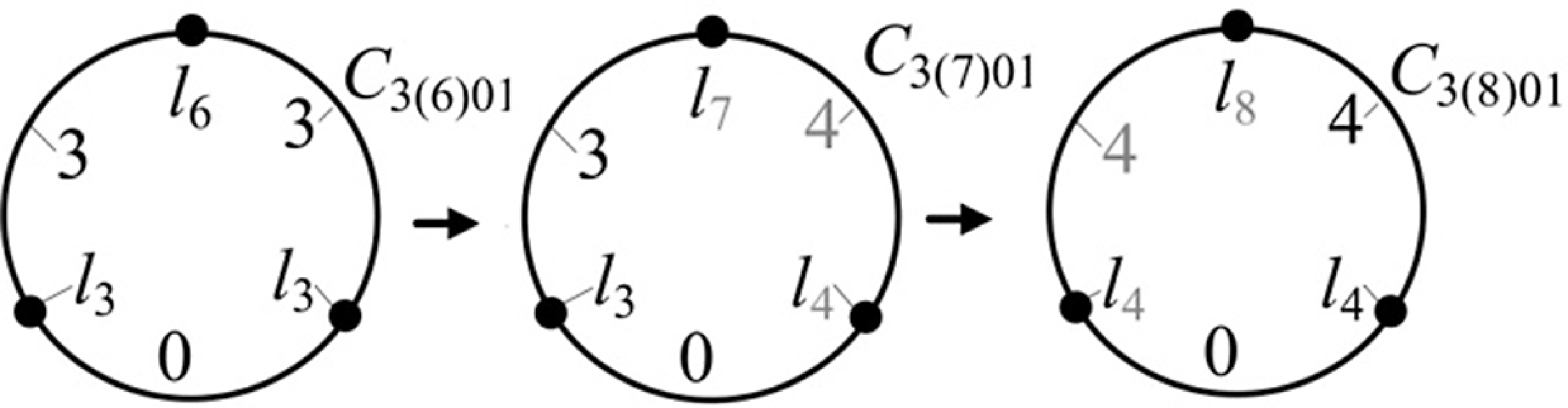
Using the digit + 1 approach, several new open C 3(k)0i with (l j , 6 ≤ j ≤ 9) can be derived from open C 3(6)01. The derivation arrows and processes are shown in Figure 4 and are explained as follows:
Derivation processes of complex open C3(k)0i with (lj, 3≤ j ≤ 8) from simple open C3(6)01.

An open C 3(7)01 with (1l 7, 1l 4, 1l 3) is derived from C 3(6)01 by changing ⎞ (l 6, 3, l 3) of C 3(6)01 into ⎞ (l 7, 4, l 4) of C 3(7)01. An open C 3(8)01 with (1l 8, 2l 4) is derived from C 3(7)01 by changing ⎛ (l 7, 3, l 3)} of C 3(7)01 into ⎛ (l 8, 4, l 4) of C 3(8)01.
4.2 Derivation of C4(k)i
Some C 4(k)i with (n = 4, l j , 3 ≤ j ≤ k) can be derived from C 4(3)1 with (n = 4, 4l 3); see Figure 2(a5). The derivation arrows and processes are shown in Figure 5 and are explained as follows.
Derivation processes of C4(4)i (i = 1, …, 5) from C4(3)1.

-
1. Using the digit + 1 approach, C 4(4)1 with (n = 4, 2l 4, 2l 3) is derived from C 4(3)1 by changing | (l 3, 0, l 3) of C 4(3)1 into | (l 4, 1, l 4) of C 4(4)1. C 4(5)1 with (n = 4, 1l 5, 2l 4, 1l 3) is derived from C 4(4)1 by changing ⎞ (l 4, 1, l 3) of C 4(4)1 into ⎞ (l 5, 2, l 4) of C 4(5)1.
-
2. Using the digit -1 approach, C 4(5)2 with (n = 4, 1l 5, 3l 3) is derived from C 4(5)1 by changing ⎠ (l 4, 2, l 4) of C 4(5)1 into ⎠ (l 3, 1, l 3) of C 4(5)2.
It is found that the derived C 4(4)1 with (2l 4, 2l 3) in Figure 5 and open C 4(4)01 with (2l 4, 2l 3) are mutually isomorphic. If an open C n(k)0i (4 ≤ n) with a line marked by a digit (1≤ digit), it can be replaced by its isomorphism.
Several open C 4(k)0i (n = 4, k = 5, 6) are derived from open C 4(4)02 in Figure 3(a4). The derivation arrows and processes are shown in Figure 6 and explained as follows.
Derivation processes of open C4(5)0i (i = 1, …3) and C4(6)0i (i = 1, …, 7) from open C4(4)02.

Figure 6 Long description
Panel A: A circular diagram labeled C4(4)02 with links l2, l3, l4, and l5. Arrows indicate transitions to the next stages. Panel B: A circular diagram labeled C4(5)01 with links l2, l3, l4, and l5. Arrows indicate transitions to the next stages. Panel C: A circular diagram labeled C4(5)02 with links l2, l3, l4, and l5. Arrows indicate transitions to the next stages. Panel D: A circular diagram labeled C4(5)03 with links l2, l3, l4, and l5. Arrows indicate transitions to the next stages. Panel E: A circular diagram labeled C4(6)01 with links l2, l3, l4, l5, and l6. Arrows indicate transitions to the next stages. Panel F: A circular diagram labeled C4(6)02 with links l2, l3, l4, l5, and l6. Arrows indicate transitions to the next stages. Panel G: A circular diagram labeled C4(6)03 with links l2, l3, l4, l5, and l6. Arrows indicate transitions to the next stages. Panel H: A circular diagram labeled C4(6)04 with links l2, l3, l4, l5, and l6. Arrows indicate transitions to the next stages. Panel I: A circular diagram labeled C4(6)05 with links l2, l3, l4, l5, and l6. Arrows indicate transitions to the next stages. Panel J: A circular diagram labeled C4(6)06 with links l2, l3, l4, l5, and l6. Arrows indicate transitions to the next stages. Panel K: A circular diagram labeled C4(6)07 with links l2, l3, l4, l5, and l6.
-
1. Using the digit + 1 approach, 2 C 4(5)0i (i = 1, 2) with (l j , 3 ≤ j ≤ 5) are derived from C 4(4)02 with (2l 4, 2l 3) by changing {⎞ (l 4, 3, l 3), ⎛ (l 4, 1, l 4)} of C 4(4)02 into {⎞ (l 5, 4, l 4), ⎛ (l 5, 2, l 5)} of C 4(5)0i (i = 1, 2), respectively. C 4(5)03 with (2l 5, 2l 4) is derived from C 4(5)01 by changing ⎝ (l 4, 3, l 3) of C 4(5)01 into ⎝ (l 5, 4, l 4) of C 4(5)03.
-
2. Using the digit + 1 approach, C 4(6)01 with (2l 6, 2l 5) is derived from C 4(5)03 by changing ⎝ (l 5, 4, l 4) of C 4(5)03 into ⎝ (l 6, 5, l 5) of C 4(6)01. Two C 4(6)0i (i = 2, 3) with (l j , 3 ≤ j ≤ 6) are derived from C 4(5)02 with (2l 5, 2l 3) by changing {⎛ (l 5, 2, l 5), ⎞ (l 5, 3, l 3)} of C 4(5)02 into {⎛ (l 6, 3, l 6), ⎞ (l 6, 4, l 4)} of C 4(6)0i (i = 2, 3), respectively. C 4(6)04 with (2l 6, 2l 4) is derived from C 4(6)03 by changing ⎝ (l 5, 3, l 3) of C 4(6)03 into ⎝ (l 6, 4, l 4) of C 4(6)04.
-
3. Using the digit -1 approach, C 4(6)06 with (1l 6, 3l 4) is derived from C 4(6)05 with (1l 6, 2l 5, 1l 4) by changing ⎝ (l 5, 4, l 5) of C 4(6)05 into ⎝ (l 4, 3, l 4) of C 4(6)06. C 4(6)07 with (1l 6, 1l 4, 2l 3) is derived from C 4(6)06 by changing ⎝ (l 4, 3, l 4) of C 4(6)06 into ⎝ (l 3, 2, l 3) of C 4(6)07.
4.3 Derivation of C5(k)i
Using the digit + 1 approach, several C 5(4)i (i = 5, …, 4) with (n = 5, more l 4) can be derived from C 5(4)4 with (n = 5, 1l 4, 4l 3) in Figure 3(a12). The derivation arrows and processes are shown in Figure 7. The derivation processes are explained as follows.
Derivation processes of C5(4)i (i = 5, …, 8) with more l4 from C5(4)4 with (1l4, 4l3).

Two C 5(4)i (i = 5, 6) with (n = 5, more l 4) are derived from C 5(4)4 with (1l 4, 4l 3) by changing {/↓ (l 3, 0, l 3), ― (l 3, 0, l 3)} of C 5(4)4 into {/↓ (l 4, 1, l 4), ― (l 4, 1, l 4)} of C 5(k)i (i = 5, 6), respectively. Two C 5(4)i (i = 7, 8) with 5l 4 are derived from C 5(4)i (i = 5, 6) by changing {\↓ (l 3, 0, l 3), ∪ (l 3, 1, l 3)} of C 5(4)i (i = 5, 6) into {\↓ (l 4, 1, l 4), ∪ (l 4, 2, l 4)} of C 5(4)i (i = 7, 8), respectively.
4.4 Derivation of C6(k)i
C 6(3)4 with (n = 6, 6l 3) in Figure 2(a16) can be used to derive C 6(4)i with (n = 6, l j , 3 ≤ j ≤ 4). The derivation arrows are shown in Figure 8. The derivation processes are explained as follows.
Derivation processes of C6(4)i (i = 1, 2, 3) from C6(3)4.

Figure 8 Long description
Panel A: A circular diagram with labeled links and values, showing the initial configuration C6(3)4. Panel B: A circular diagram with labeled links and values, showing the derived configuration C6(4)1. Panel C: A circular diagram with labeled links and values, showing the derived configuration C6(4)2. Panel D: A circular diagram with labeled links and values, showing the derived configuration C6(4)3.
Using the digit + 1 approach, C 6(4)1 with (2l 4, 4l 3) is derived from C 6(3)4 with 6l 3 by changing | (l 3, 0, l 3) of C 6(3)4 into | (l 4, 1, l 4) of C 6(4)1. C 6(4)2 with (4l 4, 2l 3) is derived from C 6(4)1 with (2l 4, 4l 3) by changing) (l 3, 1, l 3) of C 6(4)1 into) (l 4, 2, l 4) of C 6(4)2.
Using the digit-1 approach, C 6(4)3 with (2l 4, 4l 3) is derived from C 6(4)2 with (4l 4, 2l 3) by changing ⎠ (l 4, 2, l 4) of C 6(4)4 into ⎠ (l 3, 1, l 3) of C 6(4)3.
Finally, using the same way, new C 3(k)i with l j (3 ≤ j ≤ k = 11, …, 15) can be derived from derived C 3(k)i with (l j , 3 ≤ j ≤ k = 10) in Figure 3. After that, many new C 4(6 ≤ k)i can be derived from any one of C 4(k)i and C 4(k)0i in Figures 5 and 6. Many new C 5(5 ≤ k)i can be derived from any one of C 5(4)i (i = 5, …, 8) in Figure 7. Many new C 6(5 ≤ k)i can be derived from any one of C 6(4)i (i = 1, …, 3) in Figure 8.
5. Creation of novel mechanisms using C n(k)i
It is a more significant and challenging issue to derive the complex TG using derived C n(k)i and to create the novel closed mechanisms with more mechanical advantages and more useful functions using C n(k)i and its derived TG. Here, n lj is the number of links l j ; n lj l j in C n(k)i is represented by l jw (w = 1, …, n lj ). Let (R, P , P, C, U, S, S c ) be the (revolute, active prismatic, prismatic, cylinder, universal, spherical, screw) pair, respectively. Let M be the DOF of the mechanism, N l be the number of links, N j be the number of kinematic pairs, f j be the local DOF of the jth kinematic pair, ν be the redundant constraint, ν p = 3 be the redundant constraint of an independent closed sub-planar mechanism [Reference Huang, Li and Ding9, Reference Lu, Ye and Zhang13], ζ be passive DOF, and c be the complexity coefficient of the closed mechanism [Reference Lu, Ye and Zhang13]. The creation processes of several novel mechanisms are explained as follows:
-
1. Determine (c, M, ζ, υ) according to n lj (3 ≤ j) of C n(k)i and the performances of the mechanism.
-
2. Solve n l2 using a formula as below: n l2 = 6 + M + 5c + ζ-υ-Σn lj , (3 ≤ j) in [Reference Lu, Ye and Zhang13].
-
3. Distribute n l2 l 2 onto n e edges of C n(k)i , derive TG from C n(k)i , and create a novel mechanism using TG.
-
4. Calculate its M using the improved Kutzbach–Grübler formula M = 6(N l −N j −1) + Σf j + ν−ζ in [Reference Huang, Li and Ding9] to verify its correctness.
When distributing n l2 l 2 onto n e edges of C n(k)i , several rules should be considered as follows:
-
1. Two l 2 connected serially by 3 one-DOF joints can be used to replace 1S joint with 3 DOFs; one l 2 connected serially by 2 one-DOF joints can be used to replace 1 U or 1 C joint with 2 DOFs; one-DOF joint can be used to replace 1 P or 1 R or 1 S c joint with 1 DOF [Reference Johnson12, Reference Lu, Ye and Zhang13].
-
2. Generally, a mechanism may include several sub-closed planar mechanisms and/or sub-closed spatial mechanisms. The number of links of the sub-closed planar mechanism must be ≥4 when all links are connected to each other by one-DOF joint [Reference Lu, Ye and Zhang13]. The number of links of the sub-closed spatial mechanism must be ≥7 when all links are connected to each other by one-DOF joint [Reference Lu, Ye and Zhang13].
-
3. When increasing the workspace of the mechanism, the joint with more DOFs should be located onto the base. When increasing the stability of the mechanism, the joint with fewer DOFs should be located onto the base.
5.1 Creation of mechanism 1 (adjusting plate driving mechanism of airplane nozzle) using C3(4)1
The simple C 3(4)1 includes 5e and 3 dots for 2l 3w (w = 1, 2) and 1l 4; see Figures 2(a3) and 9(a). The design processes of the mechanism 1 using derived C 3(4)1 and TG 1 are explained as follows:
-
1. Determine the complexity coefficient c = 2 based on C 3(4)1 with (2l 3, 1l 4) and 3 independent sub-rings [Reference Lu, Ye and Zhang13].
-
2. Suppose that the mechanism 1 is a 2-DoF mechanism with 3 sub-closed planar mechanisms and 1C joint, (M = 2, ζ = 1 for 1C, υ = 3ν p = 9) are satisfied. n l2 is solved [Reference Lu, Ye and Zhang13] as below, n l2 = 6 + M + 5c + ζ −υ−Σn lj ≥ 3 = 6 + 2 + 5 × 2 + 1−9−(2 + 1) = 7.
-
3. Distribute 7l 2w (w = 1, …, 7) onto 5e of C 3(4)1, derive TG 1, and create the mechanism 1; see Figure 9(b, c).
Mechanism 1 and its TG 1 derived from C 3(4)1 (a) C3(4)1, (b) TG 1, (c) Mechanism 1.

The structure and the principle of mechanism 1 are explained as follows.
The mechanism 1 consists of a base l 4, an up-plate l 21, a low-plate l 22, an up-link l 23, a low-link l 24, two actuators I and II, a frame I l 31, and a frame II l 32.
The actuator I consist s of a cylinder l 25 and a piston rod l 26 connected by a P joint. The other ends of l 2w (w = 5, 6) are connected with l 4 and l 31 by 2R joints, respectively. The actuator II is composed of the frame I l 31 with a cylinder and a piston rod l 27 connected by a P joint of C joint. The other end of l 27 is connected with l 32 by the R joint of the C joint. The nozzle shell is constructed by an input circle tunnel and two symmetry output rectangle tunnels.
Mechanism 1 is located between two symmetry output tunnels. The one ends of l 2w (w = 1, 2) are connected with l 4 by 2R joints. The one ends of l 2w (w = 3, 4) are connected with l 32 by 2R joints. The other ends of l 2w (w = 1, 2) are connected with the other ends of l 2w (w = 3, 4) by 2R joints, respectively. l 31 can be driven by the actuator I to rotate with respect to l 4. l 32 can be translated by the actuator II in respect to l 31. l 2w (w = 1, 2) can be driven to oscillate in respect to l 4 for adjusting nozzle pressure and changing direction and speed of airplane.
The mechanism 1 includes N l = 10 links for {1l 4, 2l 3w (w = 1, 2), 7l 2w (w = 1,…, 7)}, N j = 12 joints for {1 P joint, 1C joint (formed by l 27, 1P joint, and 1R joint), 9R joints}. Since 1 C joint includes 1 passive DOF, υ of the mechanism 1 with 3 independent sub-closed planar mechanisms is 3υ p = 9. DOF of the mechanism 1 is calculated [Reference Huang, Li and Ding9] as below,
 \begin{equation*} M=6(N_{l}-N_{j}-1)+\sum f_{j}+\upsilon -\zeta =6\times (10-12-1)+(1+2+9)+9-1=2. \end{equation*}
Mechanism 1 has several useful functions, such as adjusting nozzle pressure, changing the direction and speed of the airplane, and improving dexterity of flying the airplane.
5.2 Creation of mechanism 2 (novel hybrid hand with multi-sensor fingers) using open C3(7)01
The simple open C 3(7)01 includes (1l 7, 1l 4, 1l 3) 7e; see Figures 4 and 10(a). The design processes of mechanism 2 using open C 3(7)01 are explained as follows:
Mechanism 2 and its TG 2 derived from C3(7)01 (a) C3(7)01, (b) TG 2, (c) Mechanism 2.

Figure 10 Long description
Panel A: A circular diagram showing the initial configuration of the mechanism with labeled links l3, l4, and l7 connected to a central point. Panel B: A linear representation of the mechanism with labeled links l3, l4, l7, l21, l22, l23, l24, and l25, and components C and R. Panel C: A detailed diagram of the mechanism showing the finger, sensor, and various links and components including l3, l4, l7, l21, l22, l23, l24, l25, C, R, P, S, and U.
Determine c = 4 based on open C 3(7)01 with (1l 7, 1l 4, 1l 3) and 6 independent sub-rings [Reference Lu, Ye and Zhang13].
Suppose that the mechanism 2 is a 4-DOF hybrid mechanism with 2 sub-closed planar mechanisms and 1C joint, (M = 4, ζ = 1 for 1C joint, υ = 2υ p = 6) are satisfied. n l2 is solved [Reference Lu, Ye and Zhang13] as below,
n l2 = 6 + M + 5c + ζ−υ−Σn lj ≥ 3 = 6 + 4 + 5 × 4 + 1−6−(1 + 1 + 1) = 22.
Distribute 22l 2w (w = 1, …, 22) onto 7e of C 3(7)01, derive TG 6, design mechanism 6, and see Figure 10(b, c).
The structure and the principle of mechanism 2 are explained as follows.
Since the 2SPU/UPU/SP type parallel mechanism can provide a large workspace and a high motion precision of a novel hybrid hand with multi-sensor fingers, the mechanism 2 is formed by the 2SPU/UPU/SP parallel mechanism in Figure 1(a) and a finger mechanism. The 2SPU/UPU/SP parallel mechanism includes N l = 9 links for (base l 4, moving platform l 7, 4 piston rods, 3 cylinder rods), N j = 11 joints for (3 P joints, 1P joint, 4U joints, 3S joints). When two SPU active limbs and one UPU active limb are driven to extend, l 6 is moved. Since the 2SPU/UPU/SP parallel mechanism has neither redundant constraint nor passive DOF, ∑f j = 3 × 3 + 4 × 2 + 4 = 21, υ = ζ = 0 are satisfied. DOF of l 6 is calculated [Reference Huang, Li and Ding9] as below,
 \begin{equation*} M=6(N_{l}-N_{j}-1)+\sum f_{j}+\upsilon -\zeta =6\times (9-11-1)+(3\times 3+4\times 2+4)+0-0=3. \end{equation*}
The finger mechanism is formed by the base l 7, central piston rod l 21, and 3 symmetry sensor-finger linkages. Each of the 3 sensor-finger linkages is formed by links l 3, l 2w (w = 1, …, 4), and l 25 with a sensor. Here, l 21 is connected with l 7 using the P joint of the C joint, and l 22 is connected with l 21 by the R joint of the C joint. l 2w (w = 2, …, 5), l 3, l 7 are connected to each other by R joints to form a planar mechanism with 2 closed sub-planar mechanisms. When l 21 is moved, each l 24 of 3 sensor-finger linkages is moved for grapping, operating, and measuring grapping force.
Since the planar mechanism has 2 sub-planar mechanisms, N l = 7 links for {5l 2w (w = 2, …, 5), 1l 3, 1l 7}, N j = 8 joints for (1C joint formed by 1 P joint and 1R joint, 6R joints), υ = 2υ p = 6 and ζ = 1 are satisfied. The DOF of one planar mechanism is calculated [Reference Huang, Li and Ding9] as below,
 \begin{equation*} M=6(N_{l}-N_{j}-1)+\sum f_{j}+\upsilon -\zeta =6\times (7-8-1)+8+6-1=1. \end{equation*}
The other two of three sensor-finger linkages are driven by l 21 to move simultaneously.
Compared with existing robot hands with multiple fingers, the mechanism 2 has more mechanical advantages, such as enlarging the DOF and workspace of the multi-sensor fingers, simplifying the mechanism, and reducing the multi-fingers weight. Mechanism 2 can be used to grape, operate, and measure grapping force.
5.3 Creation of mechanism 3 (novel large turning angle mechanism of airplane nozzle) using C3(8)01
The derived open C 3(8)01 includes (1l 8, 2l 4) and 8e; see Figures 4 and 11(a). The design processes of the mechanism 3 using open C 3(9)02 are explained as follows:
Mechanism 3 and its TG 2 derived from C3(9)02 (a) C3(8)01, (b) TG 2, (c) Mechanism 2.

Determine c = 5 based on the open C 3(8)01 with (1l 8, 2l 4) and 8 independent sub-rings [Reference Lu, Ye and Zhang13].
Suppose that the mechanism 3 is a 6-DOF hybrid mechanism with 6 SPS active linear limbs, (M = 6, ζ = 6 for 6 SPS active linear limbs, υ = 0) are satisfied. n l2 is solved [Reference Lu, Ye and Zhang13] as, n l2 = 6 + M + 5c + ζ −υ−Σn lj ≥ 3 = 6 + 6 + 5 × 5 + 6-0−(1 + 2) = 40.
Distribute 40 l 2w (w = 1, …, 40) onto 8e of open C 3(9)02, derive TG 3, and design the mechanism 3; see Figure 14(b, c).
The structure and the principle of the mechanism 3 are explained as follows.
Mechanism 3 is a serial-parallel 2−(3SPS/S) hybrid mechanism formed by two (3SPS/S) parallel mechanisms. The mechanism 3 includes a base l 41 with a central tunnel, a middle moving platform l 8 with a central tunnel, an end moving platform l 42 with a central tunnel, and 6 SPS active linear limbs with active P joint. Here, l 41 has a protruding spherical surface. l 8 has a concave spherical surface and a protruding spherical surface at its two ends. l 42 has a concave spherical surface. Two ends of 3 SPS active linear limbs are connected with l 41 and l 8 at their circumferences by S joints. Two ends of the other 3 SPS active linear limbs are connected with l 42 and l 8 at their circumferences by S joints. l 41 is connected with l 8 by an S joint. l 42 is connected with l 8 by an S joint. The mechanism 3 includes N l = 15 links for (1l 8, 1l 41, 1l 42, 6 piston rods, 6 cylinder rods), N j = 20 joints for (6 P joints, 14S joints), ∑f j = 6 × 1 + 14 × 3 = 48, ζ = 6 passive DOF due to 6 SPS active linear limbs, and υ = 0. DOF of the parallel mechanism 3 is calculated [Reference Huang, Li and Ding9] as below,
 \begin{equation*}M=6(N_{l}-N_{j}-1)+\sum f_{j}+\upsilon -\zeta =6\times (15-20-1)+(6+14\times 3)+0-6=6\end{equation*}
Compared with the existing mechanism of the airplane nozzle, mechanism 3 can be used to enlarge the turning angle of the airplane vector nozzle at high speed, vertically fly, and improve the flying performance of the airplane.
5.4 Creation of mechanism 4 (novel single-drive turn twin-rotor) using C4(5)2
The derived complex C 4(5)2 includes 7e and 4 dots for (1l 5, 3l 3); see Figures 5 and 12(a). The creation processes and principle of the mechanism 4 by C 4(5)2 are explained as:
Mechanism 4 and its TG 4 derived from C4(5)2. (a) C4(5)2, (b) TG 4, (c) front and top views of mechanism 4.

Figure 12 Long description
Panel A: A circular diagram with labeled links and joints. The circle is divided into segments with labels such as l5, l31, l32, and l33, indicating different links and their connections. Panel B: A complex network diagram representing the topology graph of the mechanism. It includes various labeled links (l21, l22, l23, etc.) and nodes connected by lines, showing the relationships and connections between different components. Panel C: Detailed front and top views of the mechanism. The front view shows motors, rotors, and various labeled links (l5, l22, l23, etc.) arranged in a specific configuration. The top view provides a different perspective of the same mechanism, highlighting the spatial arrangement of the components.
Determine c = 3 based on C 4(5)23 with (1l 5, 3l 3) and 4 independent sub-rings [Reference Lu, Ye and Zhang13].
Suppose that mechanism 4 is a 2-DoF mechanism with 4 sub-closed planar mechanisms (M = 4, ζ = 0, υ = 4υ p = 12) that are satisfied. Therefore, n l2 is solved as below,
 \begin{equation*} n_{l2}=6+M+5c+\zeta -\upsilon -\Sigma n_{lj}\geq 3=6+2+5\times 3+0-3\times 4-(1+3)=7. \end{equation*}
Distribute 7 l 2w (w = 1, …, 7) onto 7e of C 4(5)2, derive TG 4, design mechanism 8, and see Figure 12(b, c).
The structure and the principle of mechanism 4 are explained as follows.
The mechanism 4 is formed by a base l 5, a screw rod l 21, a nut l 31, a cone gear l 27, motor 1, motor 2, and two symmetry rotor linkages. Each symmetry rotor linkage includes a double cone gear l 33, a rotor l 24, a turn box l 32, a guide rod l 22, and a link l 23. It is known that l 27 and one cone gear of l 33 are meshed with each other and can be replaced by a binary link l 26 connected with l 33 and l 27 by 2R joints [Reference Johnson12]. The other cone gear of l 33 and the cone gear of l 24 are meshed with each other and can be replaced by a binary link l 25 connected with l 33 and l 24 by 2R joints. l 5 is fixed onto the fuselage. The motors 1 and 2 are fixed onto l 5. The shafts of motors 1 and 2 are connected with l 21 and l 27, respectively. l 32 is connected with l 5 by an R joint. The two ends of l 23 are connected with l 31 and l 32 by 2R joints. l 24 is connected with l 32 by an R joint. l 31 is connected with l 21 and l 22 by S c and R joints, respectively. l 21 and l 22 are connected with l 5 by R joints. The mechanism 4 includes N l = 11 links for {1l 5, 3l 3w (w = 1, …, 3), 7l 2w (w = 1, …, 7)}, N j = 14 joints for (1P joint, 1S c joint, 12R joints). Since the mechanism 8 has 4 sub-planar mechanisms, has no passive DOF, υ = 4υ p = 12 and ζ = 0 are satisfied.
DOF of the mechanism 4 is calculated [Reference Huang, Li and Ding9] as below,
 \begin{equation*} M=6(N_{l}-N_{j}-1)+\sum f_{j}+\upsilon -\zeta =6\times (11-14-1)+14+12-0=2. \end{equation*}
Other symmetry grey rotor linkage {l 3w (w = 4, …, 6), l 2w (w = 8, …, 11)} is driven by motor 1 (l 27, l 31) and motor 2 l 21 to rotate simultaneously. Motor 1 can drive the twin-rotor to turn simultaneously from the vertical position to the horizontal position. Motor 2 can drive the twin-rotor to rotate simultaneously at the same speed.
Mechanism 4 has more mechanical advantages such as twin-rotor can be driven by motors 1 and 2 to turn at the same speed from a vertical position to a horizontal position in an aircraft carrier. Its stability and safety are increased.
5.5 Creation of mechanism 5 (novel variable cone blade mechanism of helicopter rotor) using C4(6)07
The derived open C 4(6)07 includes 8e and 4 dots for (1l 6, 1l 4, 2l 3); see Figures 6 and 13(a). The creation processes of the mechanism 5 using open C 4(6)07 and derived TG 5 are explained as follows:
Mechanism 5 and its TG 5 derived from C4(6)07 (a) C4(6)07, (b) TG 2, (c) Mechanism 5.

Determine the complexity coefficient c = 4 based on C 4(6)07 with (1l 6, 1l 4, 2l 3) [Reference Lu, Ye and Zhang13].
Suppose that the mechanism 2 is a 5-DoF mechanism with 2 sub-closed planar mechanisms, (M = 5, υ = 2υ p = 6, ζ = 1 for 1C joint) are satisfied. Thus, n l2 is solved as below,
 \begin{equation*} n_{l2}=6+M+5c+\zeta -\upsilon -\Sigma n_{lj}\geq 3=6+5+5\times 4+1-6-(1+1+2)=22. \end{equation*}
Distribute 22l 2w (w = 1, …, 22) onto 8e of C 4(6)07, derive TG 5, design mechanism 2, see Figure 13(b, c).
Since the 2SPU/UPU/SP type parallel mechanism can provide a large workspace of the helicopter rotor and a high motion precision, the mechanism 5 is formed by a 2SPU/UPU/SP type parallel mechanism and a variable cone blade mechanism.
The structure and the principle of the mechanism 5 are explained as follows.
DOF of the 2SPU/UPU/SP parallel mechanism has been calculated as M = 3 in Section 5.2. The variable cone blade mechanism is connected with l 6 and is moved with l 6. It is formed by l 6, a rotor l 31, a sleeve l 32, a link l 23 in the C joint, a piston rod l 24, 3 symmetry cone blade linkages, a motor, and a sphere. The motor is fixed into the cavity of the sphere and is flexibly connected with l 4 using ropes. The sphere is connected with l 4 by an S joint. The motor shaft is connected with l 31 by an P joint. Each of the 3 cone blade linkages is formed by a blade link l 21, a support link l 22, l 31, and l 32. Here, l 31 is connected with l 32 and l 6 by C and R joints, respectively. l 21 is connected with l 31 by an R joint. The two ends of l 22 are connected with l 21 and l 32 by 2R joints. The two ends of l 24 are connected with l 32 and l 6 by R and P joints, respectively.
When l 24 is moved, l 32 and l 22 are moved along l 31, thus, l 21 is oscillated in respect to l 31. The variable cone blade mechanism has 2 sub-planar mechanisms, N l = 7 links for {4l 2w (w = 1,…, 4), 2l 3w (w = 1, 2), 1l 6}, N j = 8 joints for {1C joint (formed by 1R joint, 1P joint and l 23), 5R joints, 1 P joint}, ∑f j = 8, υ = 2υ p = 6 and ζ = 1 are satisfied. DOF of the variable cone blade mechanism is calculated as,
 \begin{equation*} M=6(N_{l}-N_{j}-1)+\sum f_{j}+\upsilon -\zeta =6\times (7-8-1)+8+6-1=1. \end{equation*}
The other two symmetry cone blade linkages are driven by l 31 and l 32 to oscillate simultaneously with respect to l 31. Meanwhile, three cone blade linkages are driven by the motor to rotate in respect to l 6.
Compared with the existing helicopter mechanism, mechanism 2 can reduce the radial extending size of the blade in order to fly in a narrow space or park in a limited shipboard, and the weight of the helicopter rotor and increase DOF, supporting rigidity of the blade, and flying stability of helicopter rotor.
5.6 Creation of mechanism 6 (novel long-stroke pumping unit with double beams) using C5(4)5
The derived complex C 5(4)5 includes 9e and 5 dots for (3l 4, 2l 3), see Figures 7 and 14. The creation processes of the mechanism 6 using derived C 5(4)5 and TG 6 are explained as follows:
Mechanism 6 and its TG derived from C5(4)5 (a) C5(4)5, (b) TG 6, (c) mechanism 6.

Determine c = 4 based on C 5(4)5 with (3l 4, 2l 3) and 5 independent sub-rings [Reference Lu, Ye and Zhang13].
Suppose that the mechanism 6 is a 1-DoF mechanism with 5 sub-closed planar mechanisms, (M = 1, ζ = 0, υ = 5υ p = 15) are satisfied. Therefore, n l2 is solved [Reference Lu, Ye and Zhang13] as below,
 \begin{equation*} n_{l2}=6+M+5c+\zeta -\upsilon -\Sigma n_{lj}\geq 3=6+1+5\times 4+0-3\times 5-(2+3)=7. \end{equation*}
Distribute 7 l 2w (w = 1, …7) onto 9e of C 5(4)25, derive TG 3, and design mechanism 6, see Figure 14(b, c).
The mechanism 6 includes a base l 41, an up-beam l 42, a low-beam l 43, a crank l 21, an oscillating rod l 22, a link l 23, an up-pulley l 31, a low pulley l 32, a top pulley l 27, a motor, a rope, a pumping rod, and a weight. l 41 is connected with l 4w (w = 2, 3) by 2R joints at the right side of the base. One end of l 21 is connected with l 41 at the left. Two ends of l 22 are connected with the other end of l 21 and l 42 at their left ends by 2R joints. l 31 is connected with l 42 by an R joint at its left end. l 32 is connected with l 43 by R joint at the left end. l 27 is connected with l 41 by an R joint at the top. The one end of the rope is connected with the left end of l 43 and wound around 2 l 3w (w = 1, 2) and l 27, the other end of the rope is connected with the pumping rod. The two ends of l 23 are connected with l 42 at its center and l 43 at its right end, respectively. When the crank is driven by the motor to rotate, the pumping rod is moved up and down with a long stroke. It is known that the two side ropes of l 31 can be replaced by two links l 2w (w = 4, 5); two side ropes of l 32 can be replaced by two links l 2w (w = 5, 6) [Reference Johnson12]. Therefore, its TG includes N l = 12 links for {3l 4w (w = 1, 2, 3), 2l 3w (w = 1, 2), 7l 2w (w = 1,…, 7)}, 16R joints.
Since the mechanism 6 includes 5 independent sub-closed planar mechanisms and has no passive DOF, υ = 5υ p = 15 and ζ = 0 are satisfied. Its M is calculated as below,
 \begin{equation*} M=6(N_{l}-N_{j}-1)+\sum f_{j}+\upsilon -\zeta =6\times (12-16-1)+16+15-0=1. \end{equation*}
Compared with the existing beam pumping unit, the mechanism 6 has more mechanical advantages such as increasing the stroke of the pumping rod and the pumping efficiency and reducing the horizontal size and volume of the mechanism.
5.7 Creation of mechanism 7 (novel landing mechanism of airplane) using C6(4)3
The derived complex C 6(4)3 includes 10e and 6 dots for (2l 4, 4l 3); see Figures 8 and 15(a). The creation processes of the mechanism 7 using C 6(4)3 and derived TG 7 are explained as follows:
Mechanism 7, its TG and derived C6(4)3. (a) C6(4)3, (b) TG 7, (c) mechanism 7 at extend/contract positions.

Figure 15 Long description
Panel A: A circular diagram with labeled segments and connections. Panel B: A network diagram showing interconnected nodes labeled with various identifiers. Panel C: A mechanical diagram depicting a structure with labeled parts including motors, gears, and wheels.
Determine c = 4 based on C 6(4)3 with (2l 4, 4l 3) and 5 independent sub-rings [Reference Lu, Ye and Zhang13].
Suppose that the mechanism 7 is a 1-DOF mechanism with 5 sub-closed planar mechanisms (M = 1, ζ = 0, υ = 5υ p = 15) are satisfied. Therefore, n l2 is solved [Reference Lu, Ye and Zhang13] as below,
 \begin{equation*}n_{l2}=6+M+5c+\zeta -\upsilon -\Sigma n_{lj}\geq 3=6+1+5\times 4+0-15-(4+2)=6\end{equation*}
Distribute 6l 2w (w = 1, …, 6) onto 10e of C 6(4)3, derive TG 5, and design the mechanism 7; see Figure 15(b, c).
The structure and the principle of the mechanism 7 are explained as follows.
It is known that a gear pair can be replaced by a binary link l 23 connected with two meshed gears l 3w (w = 1, 2) by 2R joints [Reference Johnson12]. Therefore, the mechanism 7 includes N l = 12 links for {a base l 41, a large nut l 42, an up-gear-screw rod l 31, a low-gear-screw rod l 32, a small nut l 33, a low beam l 34, an up-guide rod l 21, a low-guide rod l 22, and 4 binary links l 2w (w = 3,…, 6)}, a motor, two wheels, and N j = 16 joints for (2P joints, 2S c joints, and 12R joints) in its TG.
Two l 3w (w = 1, 2) are parallel and mutually connected with l 41 by 2R joints. The gears of l 3w (w = 1, 2) are meshed with each other. The screw rods of l 3w (w = 1, 2) are connected with the nuts of l 42 and l 33 by 2S c joints. l 2w (w = 1, 2) are parallel and mutually connected with l 41 by 2R joints. l 42 and l 33 are connected with l 2w (w = 1, 2) by 2P joints. The two ends of l 24 are connected with l 3w (w = 3, 4). 2 l 2w (w = 5, 6) are parallel to each other. The two ends of l 2w (w = 5, 6) are connected with l 42 and l 34 by 4R joints. Two wheels are fixed onto 2 l 2w (w = 4, 6), respectively. 2 l 3w (w = 1, 2) are driven by the motor and two gears of l 3w (w = 1, 2) to rotate forward and reverse, respectively. Meanwhile, l 42 and l 33 are driven by screw nuts to move forward and reverse, respectively. l 34 and two wheels are driven by l 42, l 33, and l 2w (w = 4, 5, 6) to extend and contract.
Since the mechanism 7 has 5 sub-closed planar mechanisms and no passive DOF, υ = 5υ p = 15 and ζ = 0 are satisfied. Its DOF is calculated [Reference Huang, Li and Ding9] as below,
 \begin{equation*} M=6(N_{l}-N_{j}-1)+\sum f_{j}+\upsilon -\zeta =6\times (12-16-1)+16+15-0=1. \end{equation*}
Compared with the existing landing gear of an airplane, the mechanism 7 has more mechanical advantages such as simplifying mechanism, contracting more volume, enlarging structure strength, rigidity, stability during landing.
6. Conclusions
A digit topology circle C n(k)i is a basic and effective tool for creating various novel complex mechanisms and machines. It includes n (ternary link l 3, quaternary link l 4, pentagonal link l 5, hexagonal link l 6, …). C n(k)i can be constructed using a circle, n dots, n arcs, and several lines for connecting n dots. The n dots are arranged uniformly on the circle for representing n (l 3, l 4, l 5, l 6, …).
Several simple C n(k)i (n = 2, …, 6) and three open-digit topology circle C n(k)0i are constructed. Generally, many complex C n(k)i can be derived from the simple C n(k)i by increasing one of the line or arc digits in simple C n(k)i by 1. Here, digits are the digits marked onto the line or arc and the subscripts of two links l j (3 ≤ j ≤ k) connected with the line or arc of simple C n(k)i . In some cases, some new C n(k)i can be derived from existing C n(k)i by decreasing one of the line or arc digits in existing C n(k)i by 1. Here, digits are 1 ≤ digit marked onto the line or arc, and the subscripts of two links l j (4 ≤ j ≤ k) are connected with the line or arc of existing C n(k)i . The derived open-digit topology circle C 3(k)0i (6 ≤ k ≤ 11) can be used to create novel hybrid mechanisms.
The 7 novel mechanisms with more mechanical advantages and useful functions are created using derived C n(k)i (n = 3, 4, 5, 6) and open C n(k)0i as follows:
-
1. A novel adjusting plate driving mechanism of an airplane nozzle is created using C 3(4)1. It can be used to adjust nozzle pressure, change the direction and speed of the airplane, and improve the dexterity of flying the airplane.
-
2. A novel robot hand with multi-sensor fingers is created using open C 3(7)01. It can be used to increase the DOF and workspace of the multi-sensor fingers, simplify the mechanism, reduce multi-fingers weight and to grape, operate, and measure grapping force in space, depth sea, and hospital.
-
3. A novel large turning angle mechanism of an airplane vector nozzle is created using open C 3(9)02. It can be used to increase turning angle of the airplane vector nozzle and DOF for vertically flying and improve the flying performance of the airplane.
-
4. A novel cone blade mechanism of a helicopter rotor is created using open C 4(6)07. It can reduce the radial size of the blade of the helicopter rotor in order to fly in a narrow space or park on a limited shipboard. It can be used to change the flying speed of the helicopter rotor, increase the rigidity and stability of helicopter rotor, improve the dexterity of the helicopter rotor.
-
5. A novel single-drive turn twin-rotor is created using C 4(5)2. Its twin-rotor can be driven by motors 1 and 2 to turn at the same speed from a vertical position to a horizontal position in an aircraft carrier. Its stability and safety are increased.
-
6. A novel long stroke pumping unit with double beams is created using C 5(4)5. It can be used to increase the stroke of the pumping rod and the pumping efficiency, save energy, and reduce the horizontal size and volume of the mechanism.
-
7. A novel landing mechanism of an airplane is created using C 6(4)3. It can be used to simplify the mechanism, contract more volume, and enlarge structure strength, rigidity, and stability during landing.
The calculation results of the degrees of freedoms verify the correctness of the created mechanisms.
More novel mechanisms with more mechanical advantages and useful functions can be created using C n(k)i .
The proposed derivation approach of complex digit topology circles is not only supportive to the creation of enumerated novel mechanisms and to the conceptual design of a mechanical system automatically, but also easy to make that enumeration process computable.
Author contribution
Yi Lu conceived and designed the study and wrote the article. Nijia Ye conducted data gathering.
Financial support
The authors are grateful to the National Natural Science Foundation of China (No. 91748125).
Competing interest
The authors declare that they have no conflict of interest.
Ethical standards
Not applicable under the heading. The paper does not include human experimentation and laboratory animals.
Use of AI
The authors assert that no AI tools in the research and/or writing of this paper are used.