1. Introduction
Stroke is a leading cause of disability, with over 80 million individuals living with stroke worldwide [Reference Krueger, Koot, Hall, O’Callaghan, Bayley and Corbett1]. Lower-body exoskeletons have been recently used to aid in post-stroke gait recovery [Reference Lo, Stephenson and Lockwood2], namely they have been used in physiotherapy for post-stroke individuals [Reference Rupal, Rafique, Singla, Singla, Isaksson and Virk3, Reference Hobbs and Artemiadis4], to deliver the task-specific, repetitive movements required for effective gait rehabilitation [Reference Selves, Stoquart and Lejeune5]. The use of exoskeletons in rehabilitation can assist in helping post-stroke individuals to increase their walking speed, restore their gait symmetry, and increase their range of motion, as well as aid in restoring mobility and overall functionality [Reference Lo, Stephenson and Lockwood2, Reference Louie and Eng6, Reference Federici, Meloni, Bracalenti and De Filippis7].
In the development of control strategies for lower-body exoskeletons, common areas of research include increasing the effectiveness, accuracy, and adaptability of an exoskeleton between different patients and levels of functions [Reference Wu, Liu, Liu, Chen and Guo8–Reference Chen10]. Existing control strategies have often focused on controlling predetermined gait patterns for users through trajectory-tracking control [Reference Hobbs and Artemiadis4, Reference Young and Ferris11–Reference Lv, Zhu and Gregg13]. While this can permit a moderate level of recovery through gait rehabilitation, it can result in less engagement and participation from patients, leading to insufficient improvement in gait recovery and motor learning, as well as potential user discomfort [Reference Young and Ferris11, Reference Lv, Zhu and Gregg13–Reference Wu, Wang, Wu, Wang, Ma and Zhang16]. Personalized gait training that is tailored for individual users has been shown to lead to greater gait recovery [Reference Chen10, Reference Luu, Low, Qu, Lim and Hoon17–Reference Tucker20]. Furthermore, exoskeleton control methods that offer assist-as-needed control [Reference Hobbs and Artemiadis4, Reference Louie and Eng6, Reference Young and Ferris11, Reference Moreno, Figueiredo and Pons21, Reference Lotze, Braun, Birbaumer, Anders and Cohen22], that is, where only the level of torque or power required to assist a user in reaching a goal is provided, have also shown increased gait improvements through active user engagement and participation [Reference Lv, Zhu and Gregg13, Reference Yan, Cempini, Oddo and Vitiello23].
These aforementioned control strategies require predefined dynamics models to characterize the equations of motion of the user and exoskeleton and determine the required actuator torques needed to control the exoskeleton while interacting with the user [Reference McDaid, Kora, Xie, Lutz and Battley14, Reference Moreno, Figueiredo and Pons21, Reference Brahmi, Saad, Luna, Archambault and Rahman24–Reference Wang, Li, Wang, Fang and Zhu29]. For example, in ref. [Reference Sado, Yap, Ariffin, Ghazilla and Ahmad26], exoskeleton trajectories were predicted and generated using spatiotemporal features of a users’ gait pattern, through a dual unscented Kalman filter. A dynamics model of an exoskeleton and user was used, where the user’s limb and exoskeleton were modelled as one body. An impedance-based supervisory controller was incorporated to follow a trajectory and synchronize it with the user during locomotion with a defined friction and stiffness-based torque model. Models such as these can adapt online to users and their variations in performance as well as correct for any nonlinearities and dynamic uncertainties that arise from the interaction. However, accurately defining these dynamics models is a challenge due to the complexity of the human-exoskeleton interaction, and the resulting dynamic uncertainties, nonlinearities, and perturbations that exist. Exoskeleton-user interactions can result in additional unmodelled nonlinearities such as friction and user perturbations [Reference Zhang, Wang, Tian, Peyrodie and Wang51–Reference Zhang, Cheah and Collins53]. These complex dynamics models have often been simplified by considering: (1) only the forces resulting from the interaction of the user and exoskeleton [Reference Banala, Agrawal, Kim and Scholz28], or (2) combining the exoskeleton and user as a single body [Reference Sado, Yap, Ariffin, Ghazilla and Ahmad26, Reference Sanz-Merodio, Cestari, Arevalo, Carrillo and Garcia27, Reference Wang, Van Asseldonk and Van Der Kooij44, Reference Lo Castro, Zhong, Braghin and Liao46]. A simplified dynamics model, however, is not able to represent fully the user-exoskeleton interactions, which can in turn affect the accuracy of the controller [Reference Brahmi, Saad, Luna, Archambault and Rahman24, Reference Zhang, Cheah and Collins53, Reference Torricelli54]. Therefore, these dynamics models are often unable to precisely model the interactions between the user and exoskeleton [Reference Sado, Yap, Ariffin, Ghazilla and Ahmad26, Reference Hwangbo30–Reference Yuan, Li, Zhao and Gan34].
Reinforcement learning (RL) techniques have been developed more recently to learn the dynamics models of different users, by learning user-specific optimal control parameters through automated selection and tuning [Reference Huang, Cheng, Qiu and Zhang35, Reference Pong, Gu, Dalal and Levine36]. For example, in ref. [Reference Huang, Cheng, Qiu and Zhang35], human motion trajectories for an exoskeleton were modelled with dynamic movement primitives (DMPs) to adapt to movements from the users. A coupled cooperative primitive (CCP) was used, where a user-exoskeleton interaction term was incorporated into a conventional DMP. An impedance-based spring-damper model was then used for modelling the interaction. Using imitation learning, the CCPs were first learned by observing user movement patterns, and RL was then used to solve for the scaling, damping and stiffness parameters of the coupled primitives. By learning these parameters through RL, the dynamic uncertainties and forces due to the human-exoskeleton interaction were reduced. However, traditional RL techniques such as these are constrained to discrete observation and action spaces, which are often represented as controller parameters (e.g., damping, stiffness) [Reference Wu, Liu, Liu, Chen and Guo8, Reference Huang, Cheng, Qiu and Zhang35, Reference Pong, Gu, Dalal and Levine36, Reference Zhang, Li, Nolan and Zanotto38, Reference Hamaya, Matsubara, Noda, Teramae and Morimoto39] or joint torque actions in a discrete system [Reference Khan, Tufail, Shah and Ullah40]. Storing continuous observation or action values as discrete state-action pairs can become infeasible due to the curse of dimensionality [Reference Lillicrap41].
Model-free deep reinforcement learning (DRL) methods address this limitation by directly using high-dimensional, continuous observation and action spaces needed by exoskeletons to learn from the observations of joints, including position, velocity, and acceleration, and provide continuous joint torques actions. In general, DRL has been shown to be effective in learning locomotion skills [Reference Hwangbo30, Reference Lee, Park, Lee and Lee57–Reference Liu, Lonsberry, Nandor, Audu, Lonsberry and Quinn62] and assisting in controlling certain exoskeleton joint-based actions such as maintaining user stability and knee joint movements [Reference Kumar, Ha, Sawicki and Liu47–Reference Xu50]. However, they have not yet addressed the specific challenge of learning exoskeleton control of hip-knee-ankle gait patterns desired in physiotherapy, for use in over-ground gait rehabilitation. Applying DRL to exoskeleton control problems remains very challenging as classical RL algorithms require large numbers of training samples and from numerous people, which are impractical for robots working in human-robot interaction scenarios in clinical settings especially with patients. Furthermore, the controller must be designed to adapt to different user needs as well as changing needs of the same user during gait rehabilitation. The advantage of model-free DRL is that it does not require a dynamics model and instead only learns through the direct interaction of the exoskeleton with its environment [Reference Qu32]. More information on related works for exoskeleton control is presented in detail in Section 2.
In this paper, we present the development of a generic model-free Deep Deterministic Policy Gradient (DDPG) DRL approach in order to account for varying post-stroke individuals and desired gait patterns. The controller is the first end-to-end generic DRL-based approach for over-ground exoskeleton control of multiple desired gait patterns with multiple users with varying movement functionality. In contrast to existing controllers, it does not require individualized or predefined dynamics models as needed in adaptive control strategies. It further is not constrained to learn the discrete controller parameters that are required in existing RL-based exoskeleton control techniques. The controller can adapt to the limited movements of multiple post-stroke individuals through different stages of physiotherapy by learning the torque actions for the hip, knee, and ankle joints of exoskeleton actuators. The approach is able to train on different desired gait patterns and post-stroke baseline gait patterns with varying levels of movement functionality, their user-exoskeleton interactions and perturbations, namely the DRL controller is able to actively detect the deviations from the trained desired gait pattern due to the post-stroke individual’s perturbations and existing movements and applies the necessary corrective actuator torque actions to the exoskeleton joints to minimize the joint angle error. This allows for accurate control of desired gait patterns both seen and unseen in training, and between different exoskeleton users.
In our previous work [Reference Rose, Bazzocchi and Nejat42], we developed a DRL technique for user-specific exoskeleton control, which was trained on only one user’s baseline gait pattern and one desired gait pattern obtained from the OpenSim Gait2354 model. The controller was limited in that it required training for each exoskeleton-user pair, when the movements of the post-stroke individual improved during physiotherapy sessions. Therefore, the procedure was not adaptable to changes. In contrast, this paper extends our previous DRL approach to incorporate various desired and baseline gait patterns from the same user or multiple users. These gait patterns allow the DRL controller to adapt to multiple users and multiple desired gait patterns with varying levels of movement functionality (both seen and unseen in training). This is accomplished through training the modified controller on a large dataset of gait patterns from both healthy and post-stroke individuals, as well as through the redesign of the exploration process, reward function, and deep neural network architecture. Details of the proposed DRL control scheme and the adaptations employed in this work are presented in Sections 3 and 4.
The paper is organized as follows: Section 2 provides an overview of related works on exoskeleton control, particularly model-based adaptive control techniques, RL approaches, and DRL control methods. In Section 3, the DRL controller employed in this work is developed, with the user-exoskeleton simulation environment presented in Section 4. In Section 5, the user data for training the exoskeleton controller are described. Section 6 presents and discusses test results, with concluding remarks presented in Section 7.
2. Related works
Previous research that has investigated assistive exoskeleton control techniques for adapting to different users can be categorized into: (1) model-based adaptive control techniques [Reference Sado, Yap, Ariffin, Ghazilla and Ahmad26–Reference Banala, Agrawal, Kim and Scholz28, Reference Maggioni, Reinert, LÜnenburger and Melendez-Calderon43–Reference Lo Castro, Zhong, Braghin and Liao46], and (2) RL approaches [Reference Huang, Cheng, Qiu and Zhang35, Reference Bingjing, Jianhai, Xiangpan and Lin37–Reference Khan, Tufail, Shah and Ullah40]. More recently, DRL control methods have been investigated for learning lower and upper limb exoskeleton-based joint control tasks such as assisting in fall prevention with a hip exoskeleton or augmenting knee movements with a knee-based exoskeleton [Reference Kumar, Ha, Sawicki and Liu47–Reference Xu50]. To-date, however, a DRL-based approach has not yet been applied to end-to-end exoskeleton control for over-ground gait training of desired gait patterns.
2.1. Adaptive model-based control approaches
Traditional adaptive control techniques rely on predefined dynamics models of both the exoskeleton and user to adapt to user-specific characteristics such as walking speed or step length [Reference Horst, Lapuschkin, Samek, MÜller and SchÖllhorn18, Reference Wang, Van Asseldonk and Van Der Kooij44], and to synchronize with the movements of exoskeleton users through feedback from exoskeleton-user interactions [Reference Sanz-Merodio, Cestari, Arevalo, Carrillo and Garcia27, Reference Banala, Agrawal, Kim and Scholz28, Reference Harib45, Reference Lo Castro, Zhong, Braghin and Liao46].
For example, in ref. [Reference Sanz-Merodio, Cestari, Arevalo, Carrillo and Garcia27], a compliance-based control technique was used for exoskeleton motion by tracking a user’s trunk inclination, foot pressure, and joint angles. Parameterized trajectories from an inverted pendulum model were first generated through inverse kinematics, which were controlled on spring-based exoskeleton joints with specified stiffness parameters. The generated trajectory was then used as equilibrium points for the compliance controller. This allowed the exoskeleton to slightly deviate from the equilibrium when perturbed by the user.
In ref. [Reference Wang, Van Asseldonk and Van Der Kooij44], endpoint model predictive control (MPC) was used to provide torque control on an exoskeleton modelled as a double pendulum and generate online joint trajectories. To create endpoint references for the MPC controller, walking speed, swing duration, and step length were used as inputs. The MPC controller then computed optimized joint torque actions for a full prediction horizon from a cost function based on the reference trajectory. A computed torque from the first time step was then used as the current control action. Exoskeleton joint angles and velocities were obtained as feedback for the controller, and user-specific gait assistance was used for the swing phase of a user gait pattern.
In ref. [Reference Banala, Agrawal, Kim and Scholz28], an impedance controller for an exoskeleton for assist-as-needed was demonstrated. The exoskeleton only provided active force when a user had difficulty reaching a joint angle goal on their own. The controller observed the interaction forces between the exoskeleton and their limbs using a force-field and computed the corresponding joint torques through model-based compensation. The impedance parameters and level of assistance were then adapted based on a user’s position within the force field. An impedance controller was also presented in ref. [Reference Maggioni, Reinert, LÜnenburger and Melendez-Calderon43] for providing assist-as-needed control. The endpoint stiffness of an exoskeleton modelled as a two-link pendulum was specified based on a user’s deviations throughout the phases of their gait and was altered in direction and magnitude as the exoskeleton followed a model-reference foot trajectory.
In ref. [Reference Harib45], a feedback controller with virtual constraints was developed for a lower-body exoskeleton. The controller was intended for users with spinal cord injury to walk in the exoskeleton without additional support to maintain their balance. This dynamics model of the exoskeleton and user was represented as a single body. The controller provided virtual constraint parameters to regulate both the exoskeleton’s forward hip velocity and posture to synchronize with the other exoskeleton joints. This approach was then used for offline trajectory optimization for generating gait patterns that could be followed accurately online.
In ref. [Reference Lo Castro, Zhong, Braghin and Liao46], trajectory tracking control on an exoskeleton was optimized through the use of a linear quadratic regulator (LQR), where human-exoskeleton interaction-based disturbances were also addressed. The exoskeleton was modelled as a double pendulum, with the inputs to the LQR controller composed of feedback proportional, derivative, and integral-based actions, and a feedforward reference torque. The cost function for the LQR contained weighting matrices for the state and input. Least squares estimation was then used to experimentally derive the exoskeleton dynamics model parameters for use in the controller.
The adaptive control approaches described above all require dynamics models of the user and exoskeleton to determine appropriate control actions. However, these complex dynamics models can be difficult to accurately model due to the interactions of the user and exoskeleton and their resulting nonlinear characteristics.
2.2. Reinforcement learning in exoskeleton control
Reinforcement learning for exoskeleton control has been used in a variety of tasks where an optimized or user-specific controller is desired, namely RL has been applied in exoskeleton control to: (1) find optimal parameters of adaptive controllers [Reference Huang, Cheng, Qiu and Zhang35, Reference Zhang, Li, Nolan and Zanotto38], (2) account for forces resulting from the human-exoskeleton interactions [Reference Hamaya, Matsubara, Noda, Teramae and Morimoto39, Reference Khan, Tufail, Shah and Ullah40], or (3) allow for assist-as-needed exoskeleton control [Reference Bingjing, Jianhai, Xiangpan and Lin37].
In ref. [Reference Zhang, Li, Nolan and Zanotto38], user-specific parameters of an admittance controller were learned with RL. The user-exoskeleton interaction forces were minimized when the exoskeleton was deploying a reference trajectory. This RL approach was able to tune and find optimal damping and stiffness parameters of the controller based on the user’s performance, where user-exoskeleton contact forces and joint angle error were used as observations. A similar approach with an impedance controller using RL was demonstrated in ref. [Reference van Hasselt55] for finding optimal impedance parameters for use on an upper limb exoskeleton.
Reinforcement learning was also used in ref. [Reference Khan, Tufail, Shah and Ullah40] to implement a model-reference compliance controller for tracking a reference trajectory on a lower limb exoskeleton. Q-learning was used to find optimal joint torque values for a joint-based compliance controller while tracking a reference trajectory by observing exoskeleton joint angles and velocities from a discrete-time system. A compliance controller was used to allow for user safety with the exoskeleton by permitting the user’s perturbations. The controller represented the exoskeleton joints as second-order mass-spring-damper systems. These mass-spring-damper joints were then able to comply with the user-exoskeleton interaction forces.
In ref. [Reference Hamaya, Matsubara, Noda, Teramae and Morimoto39], upper-limb exoskeleton assistive strategies were proposed for learning from user-exoskeleton interactions. A dynamics model and control policies were learned from limited user muscle activation data using model-based RL, where a user moved a simulated arm through electromyography (EMG)-based muscle-activation recordings. A policy search approach then found the optimal assistive torque needed to help the user in accomplishing a reaching task, while reducing their observed EMG signals and thus muscle effort.
In ref. [Reference Bingjing, Jianhai, Xiangpan and Lin37], an impedance controller was modelled using an actor-critic-based approach to provide assist-as-needed control on an ankle exoskeleton. This RL approach changed the amount of assistance provided to the user by adjusting the stiffness parameters of the impedance controller’s force-field, depending on the performance of the user. User performance was determined by observing the resulting tracking errors when following a reference trajectory. The controller was then able to assist users in following a sinusoidal reference pattern that was displayed on a screen for ankle movements.
The aforementioned RL-based control methods were either used for finding optimal controller parameters [Reference Huang, Cheng, Qiu and Zhang35, Reference Bingjing, Jianhai, Xiangpan and Lin37–Reference Hamaya, Matsubara, Noda, Teramae and Morimoto39] or for following a reference trajectory through spring-mass-damper-based joints [Reference Khan, Tufail, Shah and Ullah40]. However, they still required a model of the exoskeleton or its joints to determine the control torque or reference trajectory. They also only learned discrete actions such as impedance or admittance controller parameters. As RL is also typically constrained to discrete low-dimensional observation and action spaces, it is unable to learn in high-dimensional or continuous systems [Reference van Hasselt55]. However, to accurately control an exoskeleton, continuous high-dimensional observation and action spaces are needed for representing joint angles, velocities, and accelerations as well as actuator torque outputs. Discretizing these spaces would be infeasible as the required state-action pairs would become too numerous to store [Reference Lillicrap41].
2.3. Deep reinforcement learning control approaches
A key benefit of DRL for exoskeleton control is its ability to learn and provide control in high-dimensional continuous joint observations and continuous actuator torque actions. This is achieved by mapping states to actions through deep neural networks approximating the policy and value functions of RL [Reference Qu32]. The use of these continuous observation spaces allows for actuator torque actions to be learned in an end-to-end nature directly from sensory observations of joint parameters [Reference Hwangbo30, Reference Bin Peng and van de Panne56]. In particular, the advantage of model-free DRL is that it does not require a predefined dynamics model. To date, it has been used in the literature to learn: (1) human locomotion [Reference Lee, Park, Lee and Lee57–Reference Anand, Zhao, Roth and Seyfarth59], (2) control of bipedal robots [Reference Hwangbo30, Reference Gil, Calvo and Sossa60–Reference Liu, Lonsberry, Nandor, Audu, Lonsberry and Quinn62], and (3) control of upper and lower limb exoskeleton joints [Reference Kumar, Ha, Sawicki and Liu47–Reference Xu50].
In refs. [Reference Lee, Park, Lee and Lee57]–[Reference Anand, Zhao, Roth and Seyfarth59], locomotion skills for musculoskeletal models were learned with DRL, using observations of joint angles, velocities, and accelerations, and muscle activations and joint torques as actions. DRL was also used to learn motor and locomotion skills for legged and bipedal robots, with speed, distance traversed, and stability as goals in learning [Reference Hwangbo30, Reference Gil, Calvo and Sossa60–Reference Liu, Lonsberry, Nandor, Audu, Lonsberry and Quinn62]. However, unlike in the case of rehabilitative lower-body exoskeletons, bipedal robots trained with DRL tend to define rewards for robot balance and remaining upright in order for the robots to be able to walk independently. In contrast, rehabilitative lower-body exoskeletons are used to provide assistance/support as needed based on the resistance of the user wearing them and the need to consider user-exoskeleton interactions, as opposed to performing the walking task completely for the user.
In applications for exoskeletons, DRL was used for learning an optimal control method for upper limb functional electrical stimulation (FES), while a user wore a passive elbow exoskeleton [Reference Di Febbo48]. A Proximal Policy Optimization (PPO) algorithm was used to learn the control policy, where the elbow’s joint position, velocity, and acceleration were used as observations with the error from the joint angle goal. Continuous actions of electrical stimulations to the arm muscles were, thus, able to be learned to provide elbow extension motions for the user to reach desired joint angles.
In ref. [Reference Xu50], a normalized advantage function (NAF) algorithm was used to provide mirror therapy for a lower-limb exoskeleton. The approach allowed a seated patient’s impaired leg to follow their functional limb through exoskeleton joint torque actions, while maximizing the impaired leg’s EMG recorded muscle activations. This approach also aimed to minimize tracking error between a model-reference impedance controller on the functional limb and the follower controller on the impaired leg, by observing hip and knee joint angles, velocities, and a user’s muscle activations.
In ref. [Reference Kumar, Ha, Sawicki and Liu47], DRL was used for learning a policy to predict and recover from falls with an exoskeleton for fall prevention in older adults. Torque commands were sent to a hip exoskeleton to augment a user’s locomotion when a possible fall was detected. A human locomotion policy was first learned using PPO, which was used for training the fall recovery policy. The PPO algorithm was used to observe the angular position and velocity of the hip joints and learn joint torque actions for the exoskeleton hip actuator. A classifier using a support vector machine (SVM) was then trained to predict observations that could result in a fall, and the hip exoskeleton was used to validate the recovery policy by providing a torque to help the user in maintaining their balance.
In ref. [Reference Lyu, Chen, Ding and Wang49], a DRL-based rehabilitation game was developed, where a user wearing an EMG-controlled exoskeleton on their knee controlled a game character. A thigh worn EMG sensor was used to record a user’s muscle activations, and this was then transferred into movements on the exoskeleton to control the character in the game. A deep-Q network algorithm (DQN) used a convolutional neural network (CNN) to observe images from the game to determine the character’s position. The DQN controller then outputted discrete translational movement actions to control the game character. The user was then assisted in the game through the DRL agent augmenting their EMG-based exoskeleton control by providing assistive joint movements on the exoskeleton when needed based on the character movements in the game.
This paper demonstrates the advantages of using DRL to assist users as they progress through different stages of physiotherapy. In the following section, we present the development of a novel model-free generic end-to-end DRL-based control, which uses DDPG to uniquely learn different gait patterns to assist multiple users as they progress through different stages of physiotherapy and recovery. Subsequently, the DRL controller is trained on several post-stroke individuals’ existing baseline gait patterns at varying levels of movement functionality, as described in Section 4. Training on these gait patterns within the simulation environment (Section 5) will minimize the need to re-train the exoskeleton for each new user or changes in gait patterns over time. The DDPG controller can observe continuous and high-dimensional hip, knee, and ankle joint parameters of the exoskeleton user and provide the necessary exoskeleton actuator torque actions needed to accurately follow the desired gait patterns, as demonstrated by the experiments and results presented in Section 6.
3. Exoskeleton control with DRL
Our DRL approach uses the DDPG [Reference Lillicrap41] algorithm in the Keras-RL library, [Reference Plappert63] to enable end-to-end learning of a torque controller to accurately follow any desired gait pattern on a lower-body exoskeleton. We present the first use and adaptation of the DDPG algorithm for exoskeleton control of hip-knee-ankle gait patterns. The overall DRL architecture is presented Fig. 1 with respect to its main modules and information flow between them (Fig. 1(a)), as well as its corresponding control scheme block diagram (Fig. 1(b)). The DDPG framework is primarily composed of actor and critic neural networks to represent the policy and value function of RL, respectively [Reference Lillicrap41]. The actor network takes actions based on state observations (joint parameters) obtained directly from the environment and its current policy, while the critic determines the value of these actions (actuator torques) based on the observations, and receives a reward. The simulation environment contains a musculoskeletal model with an exoskeleton model attached to it within OpenSim-RL [Reference KidziŃski, Escalera and Weimer64]. As we use a model-free DRL approach, the policy only learns through the interaction of this model with the environment. The details of our DRL technique are discussed in the following sections.
Overview of DRL architecture for exoskeleton control. (a) Diagram of DRL architecture. (b) Block diagram representation of the DRL control scheme.

3.1. Deep Deterministic Policy Gradient (DDPG)
DDPG is an off-policy, model-free, actor-critic DRL technique [Reference Lillicrap41]. In this DRL framework, the agent first obtains an observation state of joint parameters from the environment,
 ${s_t}$
, and takes an actuator torque action,
 ${a_t}$
based on the actor’s policy. It receives a reward from the defined reward function,
 ${r_t}$
, as outlined in Section 3.2, below as well as joint parameter observations from the next state,
 ${s_{t + 1}}$
, in each time step,
 $t$
, and maximizes the discounted future cumulative reward
Reference Lillicrap41
:
 \begin{equation} R = \mathop \sum \limits_{i = t}^T {\gamma ^{\left( {i - t} \right)}}{r_i}\left( {{s_i},{a_i}} \right), \end{equation}
where
 $\gamma \in \left[ {0,1} \right]$
is a discounting factor used to emphasize the influence of future rewards over those immediately obtained.
The critic,
 $Q\left( {s,a} \right)$
, uses the Bellman equation to provide the Q-value, which approximates the expected return after taking exoskeleton actuator torque actions in a particular state. The actor policy,
 $\mu (s|{\theta ^\mu })$
, is parameterized deterministically by mapping specific joint observation states to torque actions and is updated by the policy gradient. The policy gradient approach works by updating the policy through gradient descent based on the
 $Q$
-value estimated by the critic network and its gradient. In this DRL algorithm, deep neural networks are used to approximate the policy and value functions [Reference Lillicrap41].
During the training process, the actor network,
 $\mu (s|{\theta ^\mu })$
, and the critic network,
 $Q(s,a|{\theta ^Q})$
, are first initialized with random weights
 ${\theta ^\mu }$
and
 ${\theta ^Q}$
. With these initial random weights, the actor policy has no initial knowledge of the value of actuator torque actions or which will be highly rewarded. Through training, the actor policy learns this by updating its weights based on the critic’s Q-value approximations.
In the DDPG algorithm, target networks are also initialized. This is based on the method used in the DQN algorithm [Reference Mnih65], where target networks based on copies of the original network weights assisted in learning. The copied actor and critic target networks aid in maintaining stability in learning and prevent divergence when the target
 $Q$
-value is determined, addressing issues that may arise from estimating the
 $Q$
-value based on the same critic network that is being updated [Reference Lillicrap41]. These networks,
 $\mu '$
and
 $Q'$
, have the following weights:
 $${\theta ^{{\mu ^\prime }}} \leftarrow {\theta ^\mu },$$
 \begin{equation} {\theta ^{Q^{\kern1pt\prime}}} \leftarrow {\theta ^Q}. \end{equation}
A replay buffer,
 $B$
, is also provided in order to store the transitions of experience, including the current and subsequent time steps’ state observations of joint parameter information, the actuator torque actions, and reward from the defined reward function
 $({s_t},{a_t},{r_t},{s_{t + 1}})$
. A random process
 $\mathcal{N}$
is used during training to encourage action exploration in the actuator torque space, based on a Gaussian white noise process.
Improving on our previous work [Reference Rose, Bazzocchi and Nejat42], we extended the DDPG implementation by adding Gaussian white noise (with
 $\sigma$
= 0.3) in order to allow for greater exploration of the action space and to avoid convergence to local minima [Reference Fujimoto, Van Hoof and Meger67]. This type of action space noise is supported in more recent updates to the DDPG algorithm [Reference Fujimoto, Van Hoof and Meger67] and improves upon the Ornstein Uhlenbeck process used in ref. [Reference Rose, Bazzocchi and Nejat42]. A higher maximum torque was used for each actuator to account for larger ranges of motion and joint speeds based on clinical data from ref. [Reference Bovi, Rabuffetti, Mazzoleni and Ferrarin78]. In the reward function, we introduced a new joint angle error linear penalization function to minimize the mean absolute error. In the actor neural network architecture of this work, a hyperbolic tangent activation function is introduced in the output layer of the network to replace the sigmoid activation function used in ref. [Reference Rose, Bazzocchi and Nejat42]. The updated activation function allows for a range of normalized actions within −1 to 1; thereby increasing the allowable range of actuator torque outputs. It also provides greater stability and performance in training than the sigmoid activation function [Reference Nwankpa, Ijomah, Gachagan and Marshall89]. Furthermore, in this work, action clipping was added to the action outputs at each time step to ensure the maximum torque was not exceeded with the exploration noise, and the absolute error at each time step of an episode for each joint was added to the observation space as input to both the actor and critic networks, thereby improving the accuracy of the controller. This work is the first application of end-to-end generic DRL-based control of exoskeletons for multiple gait patterns and users.
In each time step of training, a joint observation state is received. The observations are composed of the: (1) exoskeleton hip, knee, and ankle actuator torque and velocity, (2) joint angles, velocities and accelerations for the hip, knee and ankle joints of the musculoskeletal model, (3) the current error for each joint, and (4) the goals at the current time step. These goals are composed of the desired joint angles to be reached for all three joints of the musculoskeletal model, which over a full episode of training represent one gait cycle of the desired gait pattern.
For each subsequent time step, torque action for each actuator of the exoskeleton,
 ${a_t} = \mu \left( {{s_t}{{|}}{\theta ^\mu }} \right) + \mathcal{N}_{t},$
is performed based on the actor’s current policy and added noise for exploration [Reference Lillicrap41]. Observations from a new state and reward are then obtained. The state transition tuples,
 $({s_t},{a_t},{r_t},{s_{t + 1}})$
, are then stored in the replay buffer.
A target
 $Q$
-value,
 ${y_t}$
, is then determined based on the target networks,
 $\mu '$
and
 $Q'$
, and receives the reward
 ${r_t}$
, using the Bellman equation [Reference Lillicrap41]:
 \begin{equation} {y_t} = {r_t} + \gamma Q'\left( {{s_{t + 1}},\mu '\left( {s_{t + 1}}{{|}}{\theta ^\mu }' \right){\textrm{|}}{\theta ^{Q^{\kern1pt\prime}}}} \right). \end{equation}
The critic network weights are then updated through minimizing the mean squared error loss,
 $L$
, between the target
 $Q$
-value and the current
 $Q$
-value estimated by the critic network, over a batch of samples of state transitions gathered from the replay buffer:
 \begin{equation} L = \frac{1}{N}\mathop \sum \limits_t {{\left( {{y_t} - Q\left( {{s_t},{a_t}{\textrm{|}}{\theta ^Q}} \right)} \right)}^2}.\end{equation}
The actor network weights are then updated by following the policy gradient based on the value estimated by the critic network [Reference Lillicrap41]. The parameter optimizer for the actor and critic networks uses the Adam optimizer [Reference Kingma and Ba68] to update the network weights. This is a commonly used approach for stochastic gradient-based optimization, where a learning rate of 0.001 is used for the actor and critic networks.
The target network weights are then updated based on the original actor and critic networks; however, a soft update term is used to allow the main networks weights to be slowly tracked, which encourages stability in learning [Reference Lillicrap41, Reference Mnih65]:
 \begin{equation} {\theta ^{Q^{\kern0.8pt\prime}}} \leftarrow \tau {\theta ^Q} + \left( {1-\tau } \right){\theta ^{Q^{\kern0.8pt\prime}}},\end{equation}
 $${\theta ^{{\mu ^\prime }}} \leftarrow \tau {\theta ^\mu } + \left( {1 - \tau } \right){\theta ^{{\mu ^\prime }}},$$
with
 $\tau \ll 1$
.
As an episode progresses through each time step, the hip, knee, and ankle joint angle goals are updated in the gait patterns. Throughout a full episode, the DRL agent learns to follow all joint angles of a desired gait pattern in order to maximize the received reward and thus track the desired gait pattern.
In this implementation of the DDPG algorithm, the first layer of the actor network takes state observations as inputs and contains three hidden layers with a rectified linear unit (ReLU) activation function in each. The output layer is composed of the torque actions, with a hyperbolic tangent (tanh) activation function. The critic network has the observations and actions as inputs in its first layer and is composed of three hidden layers with ReLU activation functions, with its output layer containing the estimated
 $Q$
-value through a linear activation.
3.2. Reward function
To encourage the DRL agent to find optimal actions, a reward function is defined. The reward function is composed of the following penalties being applied: (1) when there is an offset between the desired joint angle and current joint angles of each joint, and (2) when a joint exceeds a minimum or maximum value. This reward function encourages the exoskeleton to track the desired gait patterns by minimizing the error between the desired joint angles of the musculoskeletal joint angles and also provides a penalty when a joint angle state is far from its goal. The reward function is composed of linear joint reward functions and ramp functions, improving on the Gaussian-based reward function designed in ref. [Reference Rose, Bazzocchi and Nejat42].
In training, the desired gait pattern at each episode provides the joint angle goals at each time step for the hip, knee, and ankle joints and is updated at the start of each episode.
For all joints, the total cumulative reward
 ${R_E}$
, in each episode, E, is the summation of individual joint rewards over all episode time steps,
 $n$
, and is represented as:
 \begin{equation} {R_E} = \mathop \sum \limits_{i = 0}^n \left( {{w_h}{r_{{i_h}}} + {w_k}{r_{{i_k}}} + {w_a}{r_{{i_a}}}} \right),\end{equation}
where
 ${r_i}$
is the individual reward for each joint,
 $w_i$
is the weight for each joint, with
 $h,k,a$
representing the hip, knee, and ankle joints, respectively.
The reward for a single joint at each time step,
 ${r_i}$
, is defined as:
 \begin{equation} {r_i} = {w_F}\mathcal{F}({{q_i}}) + {w_G}\mathcal{G}\left( {{q_i}} \right),\end{equation}
where
 $\mathcal{F}$
and
 $\mathcal{G}$
are reward function components, and
 ${w_F}$
and
 ${w_G}$
their weights.
 $\mathcal{F}$
provides the penalty for the joint angle error at each time step, and
 $\mathcal{G}$
represents the penalty when a defined minimum or maximum joint angle is exceeded.
 $\mathcal{F}(q_{i})$
is defined as a linear function
 $:$
 \begin{equation} \mathcal{F}({{q_i}}) = - \left| {{q_i}-{q_{{d_i}}}} \right|,\end{equation}
which is represented as the absolute difference between the joint angle,
 ${q_i}$
, and the desired joint angle,
 ${q_{{d_i}}}$
at the current time step.
To aid the agent in finding the range of ideal actions during exploration and learning, a penalty,
 $\mathcal{G}\!\left( {{q_i}} \right)$
, is also applied if a joint exceeds a defined minimum or maximum joint angle:
 \begin{equation} \mathcal{G}({{q_i}}) = - M\left( {{y_{{\textrm{max}}}}} \right) - M\left( {{y_{{\textrm{min}}}}} \right),\end{equation}
where
 \begin{equation} M\left( y \right) = \left\{ {\begin{array}{*{20}{l}}{\begin{array}{*{20}{l}}\!\!0\;\;\;\;\;\;{y \le 0}\end{array}}\\{\begin{array}{*{20}{c}}\!\!y\;\;\;\;\;\;{y \gt 0}\end{array}}\end{array}} \right.,\end{equation}
 \begin{equation} {y_{{\textrm{max}}}} = {q_i} - {q_{{\textrm{max}}}},\end{equation}
and
 \begin{equation} {y_{{\textrm{min}}}} = {q_{{\textrm{min}}}} - {q_i}.\end{equation}
 ${q_{{\textrm{min}}}}$
and
 ${q_{{\textrm{max}}}}$
above are the set minimum and maximum joint angles, respectively, and are defined as 20 degrees below and above the minimum and maximum desired joint angles. The penalty is then added only if the minimum or maximum joint angles are surpassed, by using the ramp function
 $M\left( y \right)$
. Energy consumption by the agent in not considered in the reward function, as is commonly done in DRL exoskeleton control (e.g., refs. [Reference Kumar, Ha, Sawicki and Liu47, Reference Di Febbo48, Reference Xu50, Reference Di Febbo86]), since it would limit the assistive capability of the exoskeleton. Therefore, the only restriction on energy consumption, herein, is limiting the peak torque of the system. Furthermore, for our case, impedance added from the musculoskeletal model’s muscles restrict sudden torque movements and the reward function penalizes the error that may be resulting from such sudden movements during training.
In the next section, the minimum and maximum joint angles for the exoskeleton system are defined as well as the simulation environment. The simulation environment, which includes a lower-body exoskeleton model and a human musculoskeletal model, is developed so that the DRL agent can explore and learn within a constrained action space. The exoskeleton joint angles are constrained to prevent the agent from taking actions that are unsafe or infeasible during exploration, rewarding, and penalizing joint actions according to Eq. (8).
4. User-exoskeleton simulation environment
A simulation environment in the OpenSim API platform [Reference Seth69] has been developed that includes a 3D exoskeleton model paired to a 3D musculoskeletal model. OpenSim-RL is used as the platform to provide the RL framework and environment [Reference KidziŃski, Escalera and Weimer64]. It is based on OpenAI Gym [Reference Brockman76], a widely used platform for performing DRL benchmarking and research, and utilizes the OpenSim API. To incorporate the dynamics, motion, and interaction forces between the musculoskeletal joints, muscles, bones, and exoskeleton components in the OpenSim-RL environment, the Simbody physics engine [Reference Sherman, Seth and Delp77] is used. The DRL agent described in Section 3 explores and learns through the actuation of the hip, knee, and angle joints of the exoskeleton model within the simulation environment. The inputs to the controller are the environment observations, i.e., (i) exoskeleton hip, knee, and ankle actuator torques and velocities, (ii) joint angles, velocities, and accelerations for the hip, knee, and ankle joints of the musculoskeletal model, (iii) current error in the joint angles, and (iv) the desired joint angles at the current time step. The control outputs are the individual torque actions to each of the joints.
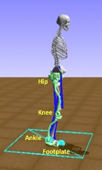
The 3D hip-knee-ankle exoskeleton model is adapted from ref. [Reference Coll Pujals70] and contains a hip attachment, and thigh, shank, and foot linkages, Fig. 2. The exoskeleton motors are added as torque actuators from the OpenSim API to each exoskeleton joint. In this work, a new exoskeleton model with 6 degrees of freedom (DOFs) is simulated based on the H2 Exoskeleton from Technaid [Reference Bortole12] and used in OpenSim. Table I presents the kinematic and dynamic specifications for the exoskeleton model. An actuator at each joint of the exoskeleton model, namely hip, knee, and ankle, provides a degree of freedom to the system. The maximum torque the actuator can provide is 220 Nm, which is aligned with the maximum torque on the H2 [Reference Bortole12]. The model used in this work improves upon the H2 exoskeleton modelled in ref. [Reference Rose, Bazzocchi, de Souza, Vaughan-Graham, Patterson and Nejat71], which was represented with simplified geometry and dynamics, that is, links and inertia tensors were modelled as rectangular prisms. The simplified model of the H2 exoskeleton is extended to include the joint angle limits as well as the dimensions, masses, and moments of inertia for each link of the exoskeleton provided in ref. [Reference Coll Pujals70] in order to closely match the H2 exoskeleton in ref. [Reference Bortole12], and more effectively model the exoskeleton and evaluate the control method proposed. Each exoskeleton joint is constrained to simulate a motion range similar to real exoskeleton joints [Reference Rose, Bazzocchi, de Souza, Vaughan-Graham, Patterson and Nejat71], and prevents unrealistic and dangerous movements during exploration or execution, such as hyperextension in the knee. The forces in the simulated environment include acceleration due to gravity, ground reaction forces on the bottom of the exoskeleton foot plates at the heel and toe, and joint limit constraints. The ground reaction forces are modelled as Hunt–Crossley Forces [Reference Hunt and Crossley72] in the OpenSim environment. This contact model creates force interactions between contact spheres that are applied at the exoskeleton’s foot plate on the heel and toe, as seen in blue on the footplate in Fig. 2, and the floor plane. The exoskeleton parameters incorporated in our simulation are summarized in Table I.
OpenSim-RL-based Simulation environment, with a hip-knee-ankle exoskeleton attached to a musculoskeletal model.

The musculoskeletal model used is adapted from OpenSim’s Gait2392 model [Reference Thelen, Seth, Anderson and Delp73]. This model represents a human subject with a height of 1.8 m and mass of 76.16 kg [Reference Thelen, Seth, Anderson and Delp73]. The muscles on this musculoskeletal model are based on a Hill-type muscle model [Reference Thelen74], each containing a muscle-tendon unit with specific properties such as muscle fibre length, tendon slack length, and maximum isometric force. Passive forces from the muscle-tendon unit are incorporated into the simulation. To simulate a post-stroke individuals’ baseline gait pattern, hip-knee-ankle joint torque patterns are applied to the joints of the musculoskeletal model through an additional torque actuator added to each musculoskeletal joint [Reference Mosconi, Nunes and Siqueira75]. In following section, gait information data from post-stroke individuals are gathered to establish datasets of desired and baseline gait patterns.
5. User data for training
User data for both the desired gait patterns and baseline gait patterns are included in training. These datasets are collected from clinical studies of post-stroke individuals and healthy users. Testing sets of desired gait patterns both seen and unseen in training are then used to validate the controller’s ability for on-the-fly adaptation of desired gait patterns, for use with multiple post-stroke exoskeleton users. The patient data provide the reference joint angle positions necessary to define the goal at each step of an episode, while the controller learns the torque values required to reach that goal based on the individual user simulated, their movements, and their interactions with the exoskeleton.
5.1. Desired gait dataset
The desired gait patterns dataset for the exoskeleton consists of ankle, knee, and hip joint angle data obtained from the walking gait of 20 healthy adults ranging in age from 22 to 72 [Reference Bovi, Rabuffetti, Mazzoleni and Ferrarin78]. These gait patterns corresponded to an average maximum range of motion in the sagittal plane of 45.6º, 61.5º, and 34.4º for the hip, knee, and ankle joints, respectively. This dataset is representative of a wide range of healthy gait patterns with similar joint angle range [Reference Horst, Lapuschkin, Samek, MÜller and SchÖllhorn79, Reference Moore, Hnat and van den Bogert80]. The subjects were recorded using a motion capture system over five trials of walking at a self-selected natural walking speed. Then, they were instructed to walk at a slower speed and also an increased speed. The subjects in this study had the following mean (SD) gait characteristics in natural walking: a step length of 0.66 m (0.06 m), stride length of 1.3 m (0.12 m), stride time of 1.1 s (0.1 s), a double support time of 13% (1.68%) of their gait cycle, and a swing time of 37% (1.97%) of their gait cycle. The joint angles sequenced from these gait patterns are defined as individual joint goals at each episode time step during training. Each episode during training consists of one full gait cycle of the desired gait pattern.
Exoskeleton parameters.

* The
 ${I_{xx}}$
,
 ${I_{yy}}$
, and
 ${I_{zz}}$
, are the moment of inertia tensor’s diagonal values.
In ref. [Reference Bovi, Rabuffetti, Mazzoleni and Ferrarin78], the subjects’ recorded gait patterns were sorted into five categories of walking speeds,
 $v$
, normalized with respect to their body heights,
 $h$
(
 $v/h$
): (1) very slow (
 $v/h \lt 0.6$
), (2) slow (
 $0.6 \le v/h \lt 0.8$
), (3) medium (
 $0.8 \le v/h \lt 1$
), (4) fast (
 $v/h \gt 1$
), and (5) natural
 $({\textrm{mean}}\ v/h = 0.71$
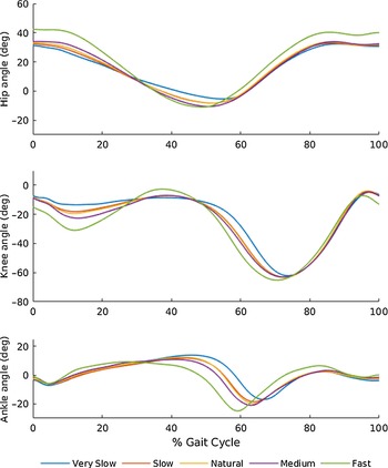
). A mean gait pattern for each of these categories was then provided. These gait patterns are represented as one gait cycle stride from heel-strike to heel-strike. Figure 3 shows the mean gait patterns of the three angle joints used for these speeds in training. For training, the episode length and duration of the gait cycle is set based on the desired gait pattern speed. This dataset also provided gait patterns for each speed that were one standard deviation from the mean gait patterns. These were then also used in training to provide additional variation in the desired gait pattern goals.
Mean desired gait patterns used in training.

To incorporate variations in desired gait, we also used scaling factors between 0.5 and 1.2, in order to simulate different stages of gait recovery towards a final healthy gait pattern, for a range of subjects with varying motor function. A healthy gait pattern typically involves increased flexion in the knee [Reference Wang, Chen, Ji, Jin, Liu and Zhang81], increased stride length, and a general increased range of motion [Reference Neckel, Blonien, Nichols and Hidler82]. These scaling factors therefore allow for setting gait pattern goals between a post-stroke individual’s existing gait pattern with limited function and a final healthy desired gait pattern. In a clinical scenario, a physiotherapist would choose the scale of desired gait pattern that best fits the current motor performance of the post-stroke individual and progressively increase this as their gait and range of motion recovers. As a post-stroke individual would have limited gait function in their affected leg [Reference Neckel, Blonien, Nichols and Hidler82, Reference Huitema, Hof, Mulder, Brouwer, Dekker and Postema83] and thus a more limited amplitude of flexion [Reference Huitema, Hof, Mulder, Brouwer, Dekker and Postema83], the range of motion for each joint in these patterns is scaled down to represent possible motion limitations in their desired gait pattern. Furthermore, these gait patterns are also scaled up to provide a larger range of motion to further challenge the user if desired, by increasing the range of motion of the gait pattern goals, which also adds variability in the training set.
As an example, the range of scaled gait joint angles for the mean natural gait pattern speed is shown in Fig. 4, where the plotted line displays the provided mean gait pattern from ref. [Reference Bovi, Rabuffetti, Mazzoleni and Ferrarin78], with the shaded region representing the scaled desired gait patterns from 0.5 to 1.2. All additional gait pattern speeds are scaled in a similar manner.
Mean desired joint angle pattern for the natural gait pattern speed, with the shaded region indicating the scaling from 0.5 to 1.2.

5.2. Baseline gait dataset
To obtain the baseline motions for the musculoskeletal model, walking gait patterns in the sagittal plane were obtained from six chronic post-stroke individuals [Reference Knarr, Kesar, Reisman, Binder-Macleod and Higginson84]. The subjects ranged in age from 54 to 70 and were between 12 months and 55 months past the date of their stroke. Selection criteria were defined as the capability to walk for 5 min at a self-selected speed in the presence of gait deficits. The post-stroke individuals had hemiparesis, or weakness, on one side of their body, which is indicated in the data. These gait patterns were captured by using a motion capture system as subjects walked at a self-selected walking speed on a split-belt treadmill. The collected motion capture data of the subjects’ gait sequences was then converted to joint angles in an OpenSim motion file format [Reference Knarr, Kesar, Reisman, Binder-Macleod and Higginson84].
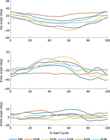
Input into the DRL training consisted of the ankle, knee, and hip joint angle data from the affected leg for one gait cycle per subject, scaled similarly as the desired gait patterns, to simulate variability functionality and recovery levels for each post-stroke individual. These baseline gait patterns were then applied to the musculoskeletal model through a torque actuator added to each of the musculoskeletal model’s hip, knee, and ankle joints using the OpenSim API. The baseline joint angle patterns for one cycle of each subject’s gait from heel strike to heel strike are shown in Fig. 5 [Reference Knarr, Kesar, Reisman, Binder-Macleod and Higginson84]. In the next section, the two datasets are employed to train the DDPG algorithm as well as to test the trained policy.
Baseline gait patterns from each post-stroke individuals’ affected leg, as named in ref. [Reference Knarr, Kesar, Reisman, Binder-Macleod and Higginson84].

6. Experiments
To validate our DRL approach for exoskeleton control, we first trained the DDPG algorithm with the desired gait pattern and baseline gait pattern sets. The resulting trained policy was then verified on desired gait patterns both seen and unseen in training.
Average reward per episode during training.

Stage 1 mean desired gait patterns and trained exoskeleton gait patterns for the hip, knee, and ankle joint.

6.1. DRL training
During training, a desired gait pattern from the dataset in ref. [Reference Bovi, Rabuffetti, Mazzoleni and Ferrarin78], a baseline gait pattern from ref. [Reference Knarr, Kesar, Reisman, Binder-Macleod and Higginson84], and a scaling factor for each were randomly chosen at each episode. The number of time steps and, thus, duration of each episode was based on the speed of the selected desired gait pattern. Training was completed for 2 million time steps, corresponding to over 10,000 episodes, on an Intel Core i7-8700 CPU, with each episode consisting of between 147 and 247 time steps. The reward function parameters and weights were defined as Σ = 0.3, μ = 0,
 ${w_F}$
= 5,
 ${w_G}$
= 1, and
 ${w_h},{w_{k,}}{w_a}$
= 1. The training and DDPG algorithm hyperparameters are
 $\gamma$
= 0.99, τ = 0.001, and a learning rate of 0.001 as adapted from refs. [Reference Lillicrap41, Reference Plappert63].
Stage 1 gait pattern error.

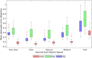
Bloxplot for Stage 1 mean absolute error of each desired gait pattern speed for each hip, knee, and ankle joints.

As can be seen in Fig. 6, the average reward per episode converged after approximately 1000 episodes, where a maximum average reward of approximately -7 was eventually reached. Prior to convergence, the controller learned a general torque pattern to follow the desired gait patterns. The reward curve fluctuates due to continual exploration by the agent while it is learning to follow the desired torque pattern. These fluctuations reduce from approximately 40 at 250 episodes to approximately 5 after 1000 episodes and remain within this later range for the duration of training. The number of steps required to control the baseline gait to reach the desired gait at each episode was equal to the episode length, which ranged from 147 to 247 steps. After convergence, the controller was able to follow the various gait patterns, and the remainder of training was used to find optimal actions for increasing the accuracy of tracking the desired gait patterns.
Stage 1 gait pattern error for each gait speed.

Stage 1 error for each baseline subject.

Stage 1 mean absolute error for each baseline gait pattern for hip, knee, and ankle joints.

6.2. Simulation runs: DRL testing
We conducted testing in two stages: (1) Stage 1: testing on desired gait patterns from the training, and (2) Stage 2: testing on a set of unseen desired gait patterns.
In Stage 1, the agent was tested for 400 episodes, corresponding to 400 gait cycles. Each desired gait pattern at each scale factor between 0.5 and 1.2 was tested 10 times. The average of 10 episodes is plotted for each gait pattern and scale factor and is presented in the results. In each episode, the baseline gait pattern from ref. [Reference Knarr, Kesar, Reisman, Binder-Macleod and Higginson84] and its scale factor were randomly chosen.
In Stage 2, five unseen walking gait patterns were obtained from additional gait information from healthy adult subjects [Reference Lencioni, Carpinella, Rabuffetti, Marzegan and Ferrarin85]. These gait patterns were not used in training. In this dataset, gait patterns with corresponding joint angles for one gait cycle from heel-strike to heel-strike were provided. Each unseen gait pattern was set to a gait pattern speed as used in Stage 1, from very slow to fast. These gait patterns were then tested at each scale factor between 0.5 and 1.2 for 10 episodes each, corresponding to 400 gait cycles in total. The baseline gait patterns and scales, as used in stage 1, were randomly selected at each episode.
6.3. Simulation results
(1) Stage 1:
Figure 7 provides the tracking performance for the desired gait patterns at various scaling factors (0.5–1.2) for all the desired gait pattern speeds (very slow to fast). As can be seen in the figure, the desired gait patterns were closely followed by the exoskeleton within the full range of scaling, including at the extremities of 0.5 and 1.2. This shows the ability of the exoskeleton to reach the various gait pattern goals that would be required as a post-stroke individual recovers their range of motion and function.
Stage 1 mean absolute error of each baseline gait pattern scale factor for each hip, knee, and ankle joint.

Joint Errors: From these plots, it can be seen that the desired gait patterns were closely tracked by the exoskeleton, where the full range of motion of each desired gait pattern scale and speed was reached for all joints. This corresponds to a maximum range of motion of 64.1º, 75º, and 41º for the hip, knee, and ankle, respectively. Furthermore, it demonstrates that the gait pattern goals desired in physiotherapy, such as increased stride length and increased flexion in the knee and ankle, can be accurately reached by the trained exoskeleton. The mean absolute error for Stage 1 is also presented in Table II. The mean absolute error and standard deviations for each joint is determined from the mean absolute error of all episodes of testing. The overall mean absolute error ranged from 0.23 degrees for the ankle to 0.47 degrees for the knee. In comparison, overall mean error was found to be lower than the model-based approach presented in ref. [Reference Harib45] with an average of 0.74 degrees, and the mean error found in ref. [Reference Xu50] (2.87–4.5 degrees) for a DRL-based lower limb exoskeleton.
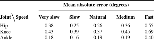
Gait Speed: The detailed boxplot for the mean absolute error for each gait pattern speed is presented in Fig. 8. The overall mean absolute error for the gait pattern speeds, as seen in Table III, ranged between 0.38, 0.43, and 0.18 degrees, for the hip, knee, and ankle joints for very slow to 0.55, 0.69, and 0.4 degrees for fast, respectively. The low error range between the desired gait pattern speeds demonstrates the ability of this controller to be used at various walking speeds, which is advantageous for different post-stroke individuals at varying stages of functional recovery. The overall error is low for all desired gait pattern speeds but increases for the fastest gait speed. This is due in part to the larger range of motion of the fastest gait pattern as seen in Fig. 3, which introduces additional error as a larger range of joint angles must be reached in a shorter amount of time. However, the desired gait patterns were still able to be tracked at all speeds as shown in Fig. 7.
Stage 2 gait pattern error.

Stage 2 desired gait patterns and trained exoskeleton gait patterns for the hip, knee, and ankle joint.

Bloxplot for Stage 2 mean absolute error of each desired gait pattern speed for each hip, knee, and ankle joint.

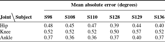
Baseline Gait: In Table IV, the mean absolute error across all tested baseline gait patterns for each joint can be seen, for each post-stroke subject (S98–S136) in ref. [Reference Knarr, Kesar, Reisman, Binder-Macleod and Higginson84]. This demonstrates the controller’s accuracy between varying exoskeleton users. A corresponding boxplot is shown in Fig. 9 of the various baseline gait patterns from the different subjects and in Fig. 10 of the baseline gait pattern scaling factors. Although it is evident that the overall mean error varied between baseline subjects and scales and was slightly higher for the subjects and joints with a larger range of motion, such as the knee joint for subject S110, the range of error was similar between the varying baseline gait patterns and scale factors. Furthermore, the mean absolute error found for each baseline subject seen in Table IV was low overall, with error ranging between 0.35–0.41 degrees in the hip, 0.52–0.51 degrees in the knee, and 0.20–0.25 degrees in the ankle, for the different users. Therefore, the controller was able to learn multiple desired gait patterns with varying baseline gait pattern inputs, while maintaining low tracking error with different exoskeleton users’ individual level of function, exoskeleton interaction, and perturbations.
(2) Stage 2:
In Stage 2, joint angle patterns from the unseen testing set were verified.
Joint Errors: The mean absolute error for the hip, knee, and ankle is presented in Table V. As expected, the overall mean absolute error was higher than in Stage 1 by 0.08, 0.06, and 0.14 degrees for the hip, knee, and ankle, respectively. However, the error was still low for all joints for these unseen gait patterns, with an average error ranging from 0.37 degrees for the ankle to 0.53 for the knee. Figure 11 presents the tracked joint angle plots of the unseen desired gait patterns, with various desired gait patterns scales from 0.5 to 1.2 for each speed. In the figure, the gait patterns were closely followed by the exoskeleton throughout the range of scale factors at each gait speed, although these gait patterns were unseen by the controller in training.
Gait Speed: Figure 12 presents the boxplots for the mean absolute error for each gait pattern speed in Stage 2. The overall mean absolute error for each speed, as seen in Table VI, ranged between 0.22 degrees in the ankle for the very slow speed and 0.67 degrees in the knee for the medium speed.
Baseline Gait: Figure 13 presents the boxplot of the mean absolute error from the various baseline gait patterns tested in Stage 2, for the different subjects (S98–S136) in ref. [Reference Knarr, Kesar, Reisman, Binder-Macleod and Higginson84]. The corresponding mean absolute errors are also shown in Table VII. The mean absolute error ranged between 0.39–0.48 degrees in the hip, 0.50–0.57 degrees in the knee, and 0.36–0.40 degrees in the ankle for the different exoskeleton users. This demonstrates the DRL controller’s ability to be used with multiple post-stroke individuals with varying levels of movement functionality, while being able to control completely unseen desired gait patterns.
Stage 2 gait pattern error for each gait speed.

Bloxplot for Stage 2 mean absolute error of each baseline gait pattern subject, as named in ref. [Reference Knarr, Kesar, Reisman, Binder-Macleod and Higginson84], for each hip, knee, and ankle joint.

We provide an overall general comparison of our mean absolute errors to those obtained from other exoskeleton control methods. It should be noted that these results were obtained using different exoskeleton systems with fewer degrees of freedom than the system employed in this work (i.e., three active DOFs or less). In general, our approach has better error than several existing adaptive model-based controllers, where their tracking error ranged from 1° to 5° [Reference Bingjing, Jianhai, Xiangpan and Lin37, Reference Lo Castro, Zhong, Braghin and Liao46]. Our mean absolute error was also lower than those reported in ref. [Reference Mosconi, Nunes and Siqueira75], where a PID controller was applied to an orthotic attached to an OpenSim human musculoskeletal model with an average tracking error of 3.8°. In comparison to other DRL-based exoskeleton control methods, which had mean absolute errors ranging from 0.12° to 0.91° [Reference Di Febbo48], 2.86° to 4.6° [Reference Xu50], and 0.41° to 1.31° [Reference Di Febbo86], respectively, our approach has comparable or better error (all our mean absolute errors were less than 0.67°), while uniquely allowing for model-free and accurate control for both seen and unseen gait patterns. This supports the ability of our DRL approach to learn and track additional desired gait patterns a physiotherapist may wish a subject to perform in a clinical session, while being robust to multiple post-stroke individuals’ baseline gait patterns and individual level of functionality.
6.4. Simulation to real-world
In order to further adapt this control scheme for use on hardware, sim-to-real techniques and transfer learning approaches would need to be employed to account for the differences in the simulated and physical actuators, exoskeleton linkages, and human model. The research topics of sim-to-real and transfer learning have their own open challenges, and there are dedicated papers solely focusing on effectively transferring simulations to real-world robotic experiments without additional training, for example, refs. [Reference Liu, Cai, Lu, Wang and Wang90]–[Reference Julian, Heiden, He, Zhang and Schaal94]. Current literature on this subject suggests including parameter, measurement, and physical characteristic noise into the model to provide robustness in training, in addition to the existing action space noise [Reference Hwangbo30], to allow for an easier transfer to hardware. The proposed DRL controller could also be adjusted to optimize the network architecture and to fine-tune the parameters of the exploration function, in order to increase sample efficiency and potentially reduce training time. Moreover, add-ons to the OpenSim platform have been developed such as actuator classes that emulate the characteristics of DC motors [Reference Nguyen, LaPre, Price, Umberger and Sup87], which would further assist in adding additional realism to the DRL simulation. Additional musculoskeletal model characteristics, for example, muscle and ligament models of greater anatomical complexity, as well as supplemental joint and muscle mechanic models, including muscle spasticity characteristics that are often found in post-stroke individuals [Reference Li, Francisco and Zhou88], could be implemented to improve the fidelity of the simulated 3D musculoskeletal model. The inclusion of such models would result in baseline gait patterns that are more realistically simulated. We will consider the design and application of such sim-to-real techniques as part of our future research work. Moreover, in order to further validate the effectiveness of our developed control strategy, future work will include conducting a detailed comparative study of multiple control strategies, including learning-based and adaptive model-based methods, on a physical exoskeleton platform.
Stage 2 error for each baseline subject.

7. Conclusions
In this paper, a novel model-free, end-to-end DRL method for control of gait patterns on an exoskeleton for overground gait training was developed capable of accounting for the varying movement functionality of post-stroke individuals and different desired gait patterns for multiple users. The DDPG algorithm was adapted to learn hip, knee, and ankle exoskeleton actuator control torque actions in an end-to-end manner, directly from observations of joint parameters for multiple users. The DRL controller was trained and then tested in a simulated 3D physics environment, with clinical data from both healthy and post-stroke individuals. Results demonstrate that the controller was able to accurately follow the desired gait patterns both seen and unseen in training. Our controller can provide gait recovery needed in physiotherapy without requiring a predefined dynamics model and is robust to varying post-stroke individuals’ baseline gait patterns and their interactions and perturbations as they progress through therapy. It can also be adapted for any lower-body exoskeleton model by adjusting the kinematic and dynamic system parameters in the simulation environment. Future work includes implementing the DRL controller on exoskeleton hardware and performing clinical user studies. In order to implement the DRL controller on a physical exoskeleton, we will explore the use of sim-to-real techniques to account for the differences that exist in the simulated and physical actuators, exoskeleton linkages, and human model. We will also design and integrate the necessary sensory, control, and communication hardware.
Funding
This research was supported by the EMHSeed Fund, the Natural Sciences and Engineering Research Council of Canada, and the Canada Research Chairs Program (CRC).
Acknowledgments
The authors would like to thank Kara Patterson, Julie Vaughan-Graham, and Dina Brooks from the Department of Physical Therapy at the University of Toronto for their input in defining rehabilitation goals and outcomes.
Conflicts of interest
None of the authors report any potential conflict of interest in respect of this research.