1. Introduction
Power grids are critical to global energy infrastructure, requiring regular inspection and maintenance of high-voltage (HV) and ultra-high-voltage (UHV) transmission lines to ensure a reliable and sustainable electricity supply. Currently, such work still depends largely on manual methods, which are inefficient, costly, and vulnerable to terrain, weather, and vegetation–compromising both accuracy and operational efficiency. Moreover, personnel must often climb transmission towers, where falls persist as a leading cause of serious accidents [Reference Nguyen, Jenssen and Roverso1–Reference Li, Zhang, Wu, Suzuki, Namiki and Wang3]. Existing climbing aids further compound these risks: they lack true adaptive capability, exhibit instability on non-linear tower surfaces, and require frequent manual intervention, increasing physical strain and introducing operational hazards. Consequently, current systems fail to adequately address the twin challenges of safety and fatigue reduction.
In recent years, research on the application of rail-climbing robots in hazardous environments such as high-altitude, radioactive, and extreme-temperature conditions has continued to grow. However, enhancing the environmental adaptability and fall prevention capability of robots under such severe conditions remains a key scientific challenge in this field.
For these reasons, significant research has been conducted in the field of rail-climbing robots. A reliable adsorption mechanism is essential for stable vertical movement and slip avoidance. Research has focused on improving adaptability through various adsorption and locomotion strategies. Yao et al. underline that reliable adhesion is the fundamental prerequisite for preventing detachment during vertical climbing [Reference Yao, Wang, Qiao, He, Liu, Li, Liu, Zou and Zhang4].
Bionic design, inspired by insects and animals’ climbing behaviors, mimics longicorn beetle claws, gecko setae, and inchworm locomotion to develop a multi-joint bionic robot, with such climbing robots usually integrating electromagnetic and permanent magnetic adhesion technologies for surface adaptation and movement performance optimization [Reference Bian, Wei, Xu and Kong5–Reference Jia, Zheng, Li, Zhang and Huang8]. For climbing on specific structures like transmission towers, mechanical clamping and magnetic adsorption are prominent solutions. Hu et al. introduced a Load Distribution Management (LDM) mechanism to optimize adhesion utilization [Reference Hu, Han, Tao and Feng9]; Jiang et al. combined wheeled locomotion with a passive curvature-adaptation mechanism using dual-hinge linkages and magnets [Reference Jiang, Ma, Ju, Wang and Xu10]; and Zhu designed an adjustable suspension magnetic adsorption unit for intelligent wall-adhesion force regulation, though its application is largely limited to ferromagnetic tracks [Reference Zhu, Ji, Li and Lai11–Reference Alkalla, Fanni, Mohamed and Hashimoto12]. A wall-climbing robot utilizing negative-pressure adhesive chain feet as its locomotion mechanism is proposed, which integrates surface adhesion and obstacle-crossing capabilities into a unified motion system. However, this design may experience instantaneous fluctuations in adhesive force when encountering foreign objects, compromising motion stability [Reference Qian and Xia13].
Mechanical clamping offers another effective approach, providing high gripping force without continuous energy input, which improves endurance on specific structural profiles [Reference Lu, Zhao, Liu and Wang14, Reference Jiang, Liu, Yang, Wan, Guo, Jiao and Hongjiang15]. Shi et al. developed a six-degree-of-freedom articulated climbing robot configuration to enhance the safety of personnel engaged in aerial maintenance tasks [Reference Du, Ge, Zhang and Xie16]. Concurrently, a novel high-voltage transmission tower climbing robot was designed, incorporating electromagnetic adhesion and clamping mechanisms into its five-degree-of-freedom manipulator system [Reference Chen, Li, Sun, Wang, Wang, Du and Yuan17].
In terms of locomotion, adaptive locomotion mechanisms adjust climbing parameters in real-time based on terrain to achieve active adaptation to complex environments [Reference Akansie, Biradar and Karthik18]. Traditional rigid-body robots often struggle on non-flat surfaces [Reference Xu, Xie, Zhang, Hu, Zhu and Shi19]. Tang et al. employed a track-attached inspection robot with a modular and separable structure [Reference Tang, Zhou, Chen, Zhang, Tang, Li and Zhou20]. Furthermore, morphological adaptation strategies exemplified by sprawl-posture transforming quadruped robots demonstrate enhanced environmental negotiation capabilities through reconfigurable structural adjustments [Reference Yuan, Wang, Wang, Shi, Wu, Li, Li, Wang and Dai21]. For rail-climbing robots, passive posture adaptation can enhance environmental adaptability and locomotion stability without active control intervention [Reference Yue, Chen, Hu, Qiao and Xu22].
Despite the proliferation of climbing robots, existing designs are ill-suited for T-shaped guide rail climbing and human-robot collaboration. The inherent safety risks of magnetic adhesion – stemming from inconsistent magnetic properties of galvanized steel and sensitivity to surface contaminants – render it unreliable for fall prevention. Bionic robots suffer from insufficient load capacity. Purely clamping-based mechanisms exhibit complex gait control that compromises continuous motion along slender rails.
Human–robot collaboration in vertical environments is fundamentally more challenging than in ground scenarios. Unlike conventional human-motion following systems, the proposed robot is designed for human–robot cooperative climbing assistance, in which a safe relative position and assistive support force are maintained during climbing. Gravity amplifies any mismatch between assistive force and human rhythm, causing sudden load transfer or pendulum-like swinging. The core difficulty lies in simultaneously regulating support force and relative position. This necessitates a force–position cooperative regulation framework capable of coordinating support-force adaptation and relative-position maintenance during climbing. This work addresses this challenge through a passive climbing-assistance paradigm, where the robot continuously regulates its climbing velocity and assistive support force according to the relative human–robot position, thereby achieving coordinated climbing assistance.
Compared with existing climbing robots, the proposed system distinguishes itself in both mechanical design and control strategy. Unlike magnetic-adhesion and conventional clamping-based climbing robots, the proposed robot incorporates a self-balancing eccentric anti-fall mechanism that adaptively regulates the wheel–rail interaction in response to changes in the operating conditions, thereby ensuring reliable anti-fall performance and continuous stable climbing on T-shaped guide rails. In addition, rather than focusing solely on autonomous locomotion or structural adaptability, the proposed robot is specifically designed for human–robot cooperative climbing assistance, where maintaining a safe relative position between the robot and the worker is the primary control objective. Accordingly, a force–position adaptive control strategy is developed by exploiting the interaction among the assistive support force, climbing velocity, and the self-balancing eccentric mechanism, enabling coordinated regulation of support force and relative position during human–robot cooperative climbing.
Based on the above considerations, this paper proposes a force–position adaptive climbing-assistance robot featuring a self-balancing eccentric anti-fall mechanism and a force–position cooperative control strategy for safe human–robot collaborative climbing on T-shaped guide rails. The interaction among the relative human–robot position, eccentric angle, climbing velocity, and assistive support force provides the physical basis for the proposed force–position cooperative control strategy. The remainder of this paper is structured as follows. Section 2 details the mechanical design of the climbing-assist system, explaining its adaptive mechanism for complex tower structures. Section 3 presents the force–position adaptive control algorithm for safe and efficient human–robot cooperative climbing assistance. The control framework is established based on the kinematic characteristics and force-transmission mechanism of the proposed climbing system. Section 4 validates and optimizes the system’s dynamic performance through ADAMS simulations. Section 5 conducts physical prototype experiments to evaluate the system’s assistive performance and control accuracy. Finally, Section 6 summarizes the work and suggests directions for future research.
2. Robot mechanism design
2.1. Overall configuration
A systematic design of the robot’s core mechanical structure and transmission system is imperative, both for stable climbing on the dedicated T-shaped guide rail (Figure 1) and for adaptive lifting force adjustment with reliable fall prevention. This chapter presents the overall configuration and the key component designs developed to fulfill these objectives.
A cross-sectional view of a T-shaped guide rail.

The robot consists of four main subsystems as shown in Figure 2: a multi-stage compound transmission, a rubber-wheel clamping climbing module, a self-balancing anti-fall mechanism, and an electrical control unit. All subsystems are integrated within the robot frame, forming a compact overall structure. The power transmission and self-balancing anti-fall mechanism are positioned in the mid-rear section, with the rubber-wheel clamping climbing module symmetrically mounted along the midline of the chassis. Each subsystem is elaborated in the following sections.
Schematic of the robot system composition.

2.2. Analysis of rubber-wheel clamping climbing module
This design employs a three-point clamping mechanism, as shown in Figure 3, whose core principle lies in utilizing its geometric configuration to achieve passive mechanical self-locking. The three wheels are arranged at specific angles to naturally envelop the rail profile, while the robot’s self-weight is automatically resolved into three mutually distinct normal forces. These forces constitute a stable mechanical self-locking system in space, with their resultant consistently oriented toward the interior of the guide rail. This ensures continuous and reliable contact pressure and friction between the wheels and the guide rail under any orientation, without requiring active control, thereby significantly simplifying the control system and enhancing inherent safety and reliability. Furthermore, the left and right driving wheels symmetrically clamp onto a T-shaped guide rail, providing lateral guiding constraints that prevent the robot from side-slipping or derailing during vertical operations.
Principle of three-point clamping mechanism.

Figure 3. Long description
Panel A: A diagram showing the central rubber wheel positioned between the left and right drive wheels. The contact area between the wheels is highlighted. Panel B: A diagram depicting the three-point clamping mechanism in action. The central rubber wheel is in contact with a track, and the left and right drive wheels are connected to a transmission shaft. The forces acting on the wheels are indicated by arrows labeled F_n.
The geometric configuration of the wheel arrangement predetermines the force distribution, resolving the robot’s self-weight into positive normal forces that generate sufficient friction to counteract gravity and achieve self-locking. Through rational design of the geometric profiles and wheel angles, the self-locking condition can be satisfied, enabling stable self-locking inherently through the geometric configuration itself.
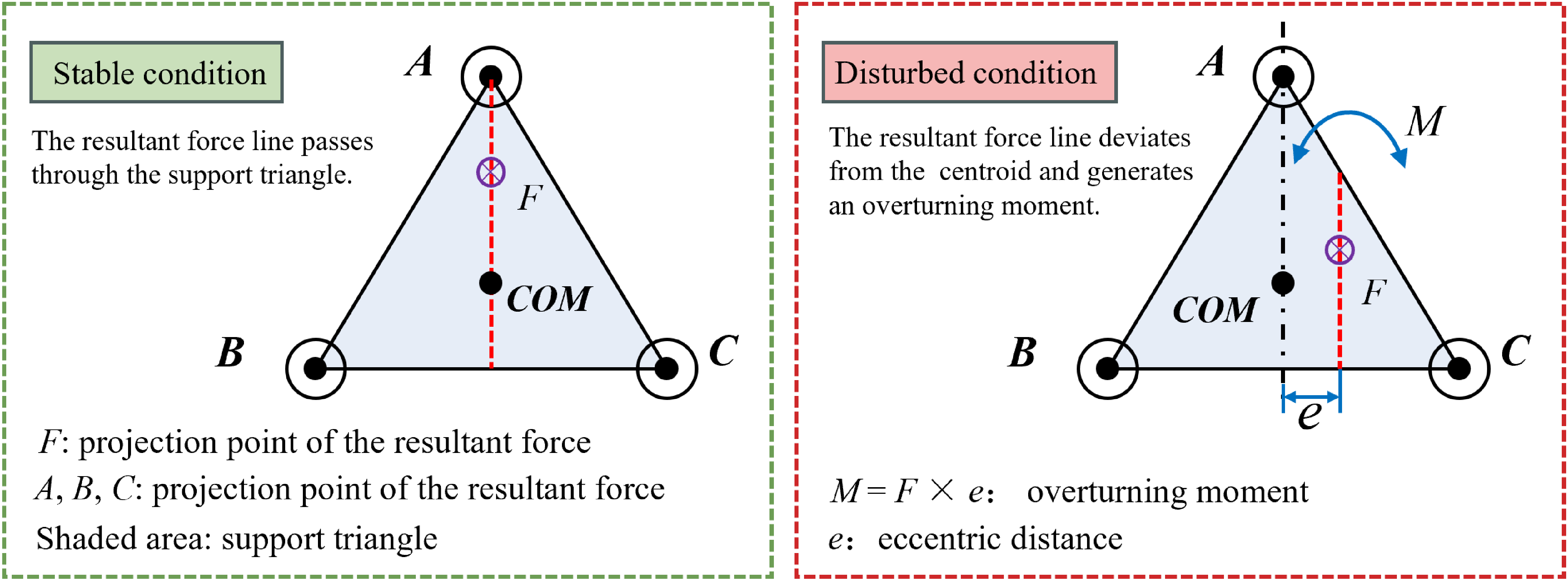
In practical applications, local rail irregularities such as welding seams, corrosion products, or manufacturing tolerances may alter the wheel–rail contact conditions. Owing to the three-point clamping configuration, the robot remains statically constrained even when one contact point experiences a temporary disturbance. The remaining contact points redistribute the contact forces and contribute to maintaining rail engagement and traction capability. Consequently, local rail irregularities primarily influence the instantaneous force distribution rather than the overall stability of the system. The stability of the robot is evaluated according to the support-region criterion defined by the three wheel–rail contact points rather than requiring the projection of the resultant force to pass through the geometric centroid of the support triangle. Although the resultant force line may shift away from the centroid of the support triangle, static stability is maintained as long as its projection remains within the support region formed by the three wheel–rail contact points. Accordingly, the influence of local rail irregularities is primarily reflected by the redistribution of the wheel–rail contact forces rather than by the loss of stability. When the resultant force approaches the boundary of the support region, the resulting overturning moment is constrained by the geometric confinement of the T-shaped guide rail. Figure 4 schematically illustrates the stability of the robot under normal and disturbed contact conditions.
Schematic illustration of the robot stability under different contact conditions.

The three wheels can be coordinately driven to provide multi-point synergistic traction, demonstrating excellent dynamic fault tolerance. In the event of a single wheel encountering slippage, the remaining two wheels continue to supply effective traction due to the non-collinear wheel arrangement and the sustained clamping forces. Crucially, the plane defined by the three wheels facilitates adaptive motion adjustment through its inherent geometric constraints. This allows a slipping wheel to naturally regain effective frictional contact after traversing a local obstacle, enabling an automatic recovery of traction force. This mechanism significantly improves the system’s operational robustness in the guide rail environments.
2.3. Configuration of self-balancing anti-fall mechanism
The self-balancing anti-fall mechanism serves as a critical safety guarantee for the system. Its core is a passively rotatable eccentric cylindrical shaft, installed at the bottom of the robot and normally kept in close contact with the guide rail. The schematic diagram of its structure is shown in Figure 5. When the robot climbs vertically along the transmission line rail while carrying tools or operating in coordination with inspectors, and experiences accidental sliding or loss of traction, the eccentric shaft will automatically rotate by a predetermined angle under the combined action of gravity and the pre-load of the mechanism. This rapid transition from a conforming state to mechanical jamming with the guide rail structure achieves instantaneous self-locking without external control commands, effectively arresting motion and preventing a fall.
Schematic diagram of self-balancing anti-fall mechanism.

By adjusting the angle between the eccentric cylindrical shaft and the guide rail, the robot’s lifting force and climbing velocity can be modulated. Acting as a mechanical advantage controller, this mechanism converts rotational input into precise vertical motion: increasing the eccentric angle raises the velocity but reduces the lifting force, and vice versa. This power-focused configuration allows the robot to handle heavier payloads or greater resistance at lower climbing velocity, enhancing mission flexibility.
2.4. Multi-stage compound transmission system
As the core drive unit, the multi-stage compound transmission efficiently delivers motor power and torque to the climbing wheels through spur gears and belt pulleys. This design ensures precise rotational velocity synchronization across the entire set of wheels, significantly reduces transmission losses, and coordinates the motion of all drive points, thereby avoiding mechanical jamming and uneven wear caused by velocity mismatch. Figure 6 illustrates the structural layout of the robot’s transmission system, where the orange arrow indicates the power transmission path.
Power transmission of multi-stage compound transmission system.

2.5. Reliability design and performance analysis of the mechanism
2.5.1. Kinematics analysis
The robot’s velocity relationship can be expressed by Eq. (1). This indicates that the robot’s overall translational velocity can be modulated by adjusting either the effective rolling radius Ri of the climbing wheels or the rotational velocity ni of the drive motors. This dual-parameter control strategy provides operational flexibility, allowing the system to maintain optimal climbing performance under varying load conditions and guide rail surface properties:
 \begin{equation} v=2\pi R_{i}n_{i} \end{equation}
where v, Ri , and ni denote the robot’s climbing velocity, the effective rolling radius of the climbing wheels, and the rotational velocity of the drive motors, respectively.
2.5.2. Quasi-static equilibrium analysis
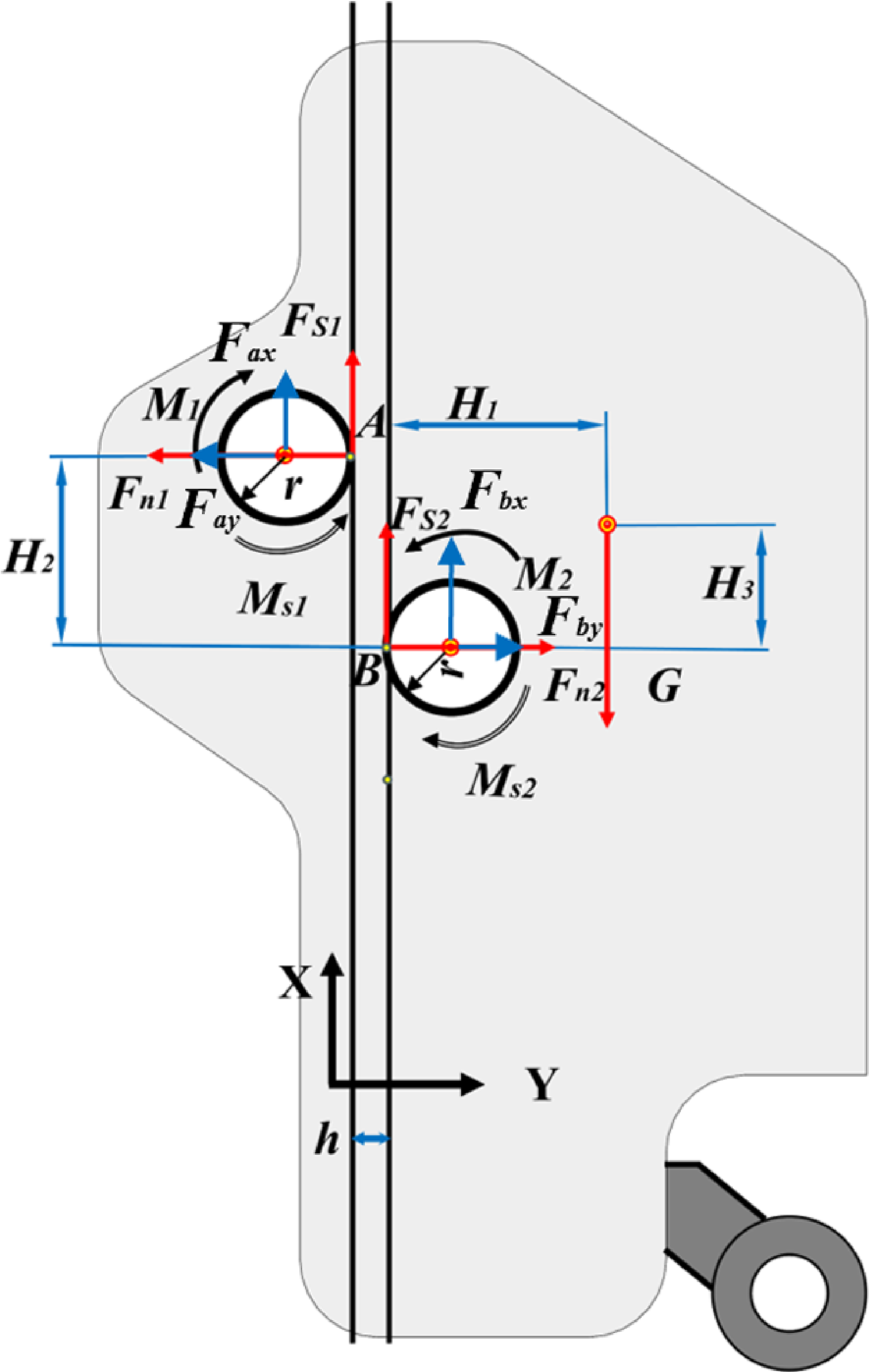
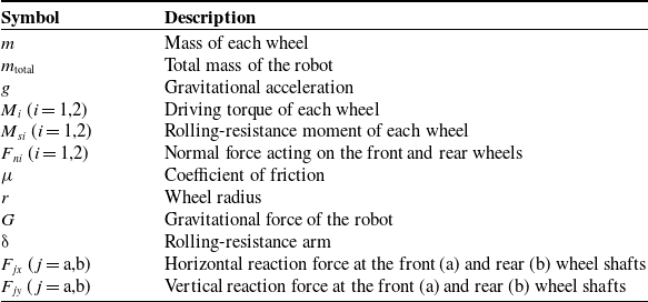
This section analyzes the force distribution during climbing (Figure 7) to assess mobility performance, which is critical for stability and safety. Under the constant-velocity assumption, a quasi-static force-equilibrium model is established to analyze the force distribution during climbing. The proposed force-equilibrium model is used to determine the required wheel torque and to evaluate the robot’s capability to maintain climbing equilibrium. Based on the proposed force-equilibrium model together with the robot mass, wheel geometry, wheel–rail friction, and rolling resistance, the required motor torque for climbing equilibrium on T-shaped guide rails is determined. The parameters used in this analysis are summarized in Table I.
Force distribution in the climbing process.

Figure 7. Long description
A diagram of the force distribution during climbing. The diagram features two circular objects labeled M1 and M2, connected by a vertical line. Various forces and moments are indicated with arrows and labels. Key components include Fax, Fay, Fn1, Ms1, Fs1, Fs2, Fby, Fbx, Fn2, Ms2, and Ms1. The distances H1, H2, and H3 are marked horizontally, and the height h is marked vertically. The diagram includes the X?Y coordinate system.
Since the left and right front drive wheels are structurally symmetric and subjected to identical loading conditions, only one side drive wheel is considered in the following force-equilibrium analysis.
Mechanical parameters used in the proposed force-equilibrium model.

Table I. Long description
A table listing mechanical parameters for a force-equilibrium model. The table has two columns: Symbol and Description. It contains 14 rows with the following data: Row 1: Symbol, m; Description, Mass of each wheel. Row 2: Symbol, m_total; Description, Total mass of the robot. Row 3: Symbol, g; Description, Gravitational acceleration. Row 4: Symbol, M_i (i = 1,2); Description, Driving torque of each wheel. Row 5: Symbol, M_si (i = 1,2); Description, Rolling-resistance moment of each wheel. Row 6: Symbol, F_ni (i = 1,2); Description, Normal force acting on the front and rear wheels. Row 7: Symbol, μ; Description, Coefficient of friction. Row 8: Symbol, r; Description, Wheel radius. Row 9: Symbol, G; Description, Gravitational force of the robot. Row 10: Symbol, δ; Description, Rolling resistance arm. Row 11: Symbol, F_fh (j = a,b); Description, Horizontal reaction force at the front (a) and rear (b) wheel shafts. Row 12: Symbol, F_fv (j = a,b); Description, Vertical reaction force at the front (a) and rear (b) wheel shafts.
The force-equilibrium equations for the front wheel are as follows:
 \begin{equation} Fs_{1}+F_{ax}=0 \end{equation}
 \begin{equation} F_{n1}+F_{ay}=0 \end{equation}
 \begin{equation} M_{1}-Fs_{1}r-Ms_{1}=0 \end{equation}
The wheel–rail friction force acts opposite to the relative slipping tendency at the contact interface and is bounded by:
 \begin{equation} F_{s1}\leq \mu F_{n1} \end{equation}
The force-equilibrium equations for the rear wheel are as follows:
 \begin{equation} F_{s2}+F_{bx}=0 \end{equation}
 \begin{equation} F_{n2}+F_{by}=0 \end{equation}
 \begin{equation} M_{2}-F_{s2}r-M_{s2}=0 \end{equation}
The available wheel–rail traction force is bounded by:
 \begin{equation} F_{s2}\leq \mu F_{n2} \end{equation}
Force equilibrium equation for the entire system:
 \begin{equation} 2F_{s1}+F_{s2}-G=0 \end{equation}
 \begin{equation} F_{n1}-F_{n2}=0 \end{equation}
 \begin{equation} G=m_{\text{total}}g \end{equation}
The rolling-resistance moment of the drive wheel is expressed as:
 \begin{equation} M_{s1}=\delta F_{n1} \end{equation}
 \begin{equation} M_{s2}=\delta F_{n2} \end{equation}
3. Force–position cooperative control strategy
3.1. Control principle and architecture
The proposed control framework aims to achieve human–robot cooperative climbing assistance rather than direct human-motion tracking. During climbing, the robot continuously regulates its climbing velocity and assistive support force according to the relative human–robot position, thereby maintaining a safe interaction distance while providing continuous load-bearing support and anti-fall protection. Through the coordinated regulation of climbing velocity and assistive support force, the robot assists the user in a safe and adaptive manner throughout the climbing process. The overall principle of the proposed human–robot cooperative climbing-assistance strategy is illustrated in Figure 8.
Principle of human–robot cooperative climbing assistance based on eccentric-angle regulation.

As illustrated in Figure 8, the proposed climbing-assistance strategy is based on the force transmission principle of the self-balancing anti-fall mechanism. During operation, the measured relative human–robot position is used to determine the corresponding eccentric-angle adjustment. The variation of the eccentric angle simultaneously influences the climbing velocity and the assistive support force, thereby establishing the physical relationships exploited by the proposed controller. Specifically, an increase in relative position results in a larger eccentric angle, leading to lower climbing velocity and higher assistive force, whereas a decrease in relative position produces the opposite effect. Accordingly, the interaction among the relative human–robot position, eccentric angle, climbing velocity, and assistive support force provides the physical basis for the proposed force–position cooperative control strategy. Based on these relationships, the controller regulates the climbing velocity through eccentric-angle adjustment to maintain a safe relative human–robot position while providing adaptive assistive support.
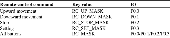
The proposed system is equipped with a wireless remote-control unit consisting of a handheld transmitter and a receiver module. Through the remote controller, the operator manually issues the commands for upward movement, downward movement, stopping, and system setting. The corresponding command definitions are summarized in Table II. Accordingly, the operator is responsible for selecting the climbing direction and issuing the commands for motion initiation, stopping, and reversal. Once a motion command is received, the proposed controller continuously regulates the climbing velocity according to the relative human–robot position throughout the climbing process.
Remote-control command definitions.

Table II. Long description
A table with four rows and three columns. The columns are labeled Remote-control command, Key value, and IO. The rows are as follows: Row 1: Upward movement, RC_UP_MASK, P0.0. Row 2: Downward movement, RC_DOWN_MASK, P0.1. Row 3: Stop, RC_STOP_MASK, P0.2. Row 4: Setting, RC_SET_MASK, P0.3. Row 5: All buttons, RC_MASK, P0.0/P0.1/P0.2/P0.3.
The proposed force–position adaptive controller adopts a dual closed-loop control architecture consisting of an inner current loop and an outer position loop. The inner current loop measures the motor current through the controller’s ADC module and regulates the PWM duty cycle using a Proportional-Integral-Derivative (PID) controller, achieving a response time of less than 0.5 ms. The outer position loop estimates the relative human–robot position from the tilt sensor and generates the target climbing velocity using the proposed velocity-adaptive strategy.
3.2. Real-time load analysis model
Load force estimation is realized through the interaction between the motor current sampling and the proposed model. The system acquires the motor current at a frequency of 1 kHz via the current sense amplifier and the ADC module of the controller, with a sampling resolution of 10 bits and a common-mode rejection ratio (CMRR) of over 80 dB. The current–force mapping model is established through experimental calibration using the least-squares method:
 \begin{equation} F\left(t\right)=k_{I}\cdot I\left(t\right)+b_{I}+\Delta F_{dyn} \end{equation}
In Eq. (15), kI represents the current-force conversion coefficient, bI denotes the static offset, and ΔFdyn is the dynamic compensation term introduced to compensate for variations in the force-transmission characteristics caused by changes in climbing conditions and external disturbances, whose detailed calculation formula is given below:
 \begin{equation} \Delta F_{dyn}=m\cdot \ddot{\!x}+c\cdot \dot{\!x}+k\cdot \left(x-x_{0}\right) \end{equation}
In Eq. (16), m is the mass of the robot, c is the damping coefficient, k is the elastic coefficient, x is the real-time distance, and x 0 is the initial position. The mechanical equation is converted into a frequency-domain transfer function through the Laplace transform to achieve real-time calculation of dynamic load force.
3.3. Force–position cooperative control framework
The force–position cooperative control framework adopted in this section is established according to the force-transmission characteristics of the climbing system. The interaction among the assistive support force, climbing velocity, and eccentric angle provides the physical basis for the proposed force–position cooperative control strategy.
For clarity, the principal control variables are defined as follows. The assistive support force F, climbing velocity v, and eccentric angle θ are selected to describe the operating state of the climbing-assistance robot. The driving torque T generated by the motor and the eccentric-angle adjustment Δθ are regarded as the control inputs. The relative human–robot position, obtained from the relative-position detection device, serves as the feedback variable for the proposed controller, while the assistive support force and climbing velocity are treated as the control outputs.
During climbing, the relative-position detection device continuously monitors the relative human–robot position. According to the detected relative-position state, the controller updates the target climbing velocity. The motor velocity is subsequently regulated by a PID controller to track the target velocity. Consequently, the robot continuously maintains the relative human–robot position within a predefined safe range while providing adaptive climbing assistance.
3.4. Relative-position-based velocity-adaptive control
3.4.1. Purpose of velocity-adaptive control
When different workers use the device to climb the tower, their climbing velocities vary. Even for the same worker, climbing velocity differs due to physical strength and environmental conditions. To expand the application scope of the device and enhance its adaptability to climbing velocity, it is necessary to dynamically control the movement velocity of the device based on the relative position between the device and the worker. Accordingly, the objective of the proposed velocity adaptation strategy is not to reproduce the user’s exact climbing motion but to maintain an appropriate relative position between the robot and the user while ensuring effective climbing assistance and operational safety.
3.4.2. Relative position detection mechanism
The safety belt of the fall prevention device is equipped with a relative position detection device, which mainly consists of three tilt sensors. The detection device is connected to the main device through an electrical interface. The device estimates the relative position level between itself and the worker by detecting the status of the three tilt sensors in combination with its own movement direction and adjusts the climbing velocity accordingly.
The tilt sensors equipped in this device are switch-type sensors, as shown in Figure 9. Let θ 1 denote the sensor tilt angle and θ 2 represent the switching threshold; the sensor is in the OFF state when θ 2 > θ 1 and in the ON state when θ 2 < θ 1.
Schematic diagram of the tilting sensor status.

3.4.3. Relationship between tilt sensor states and robot motion
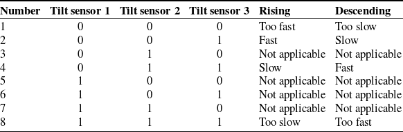
The tilt sensors are switch-type devices that output 0 in the conducting (ON) state and 1 in the disconnected (OFF) state. The three sensors are numbered according to their positions: sensor 3 is closest to the robot, sensor 1 is closest to the worker, and sensor 2 is in between. Their combined states form a 3-bit status variable, where bit 2 corresponds to sensor 3, bit 1 to sensor 2, and bit 0 to sensor 1. Based on this status and the movement direction (upward or downward), the relationship between the robot’s velocity and the worker’s velocity can be inferred, as summarized in Table III.
The relationship between the movement of the device and the tilt sensor.

Table III. Long description
A table with 8 rows and 5 columns. The columns are labeled Number, Tilt sensor 1, Tilt sensor 2, Tilt sensor 3, Rising, and Descending. The table shows the state of three tilt sensors and the corresponding movement of the device. Row 1: Number 1, Tilt sensor 1 0, Tilt sensor 2 0, Tilt sensor 3 0, Rising Too fast, Descending Too slow. Row 2: Number 2, Tilt sensor 1 0, Tilt sensor 2 0, Tilt sensor 3 1, Rising Fast, Descending Slow. Row 3: Number 3, Tilt sensor 1 0, Tilt sensor 2 1, Tilt sensor 3 0, Rising Not applicable, Descending Not applicable. Row 4: Number 4, Tilt sensor 1 0, Tilt sensor 2 1, Tilt sensor 3 1, Rising Slow, Descending Fast. Row 5: Number 5, Tilt sensor 1 1, Tilt sensor 2 0, Tilt sensor 3 0, Rising Not applicable, Descending Not applicable. Row 6: Number 6, Tilt sensor 1 1, Tilt sensor 2 0, Tilt sensor 3 1, Rising Not applicable, Descending Not applicable. Row 7: Number 7, Tilt sensor 1 1, Tilt sensor 2 1, Tilt sensor 3 0, Rising Not applicable, Descending Not applicable. Row 8: Number 8, Tilt sensor 1 1, Tilt sensor 2 1, Tilt sensor 3 1, Rising Too slow, Descending Too fast.
3.4.4. Velocity-adaptive control strategy
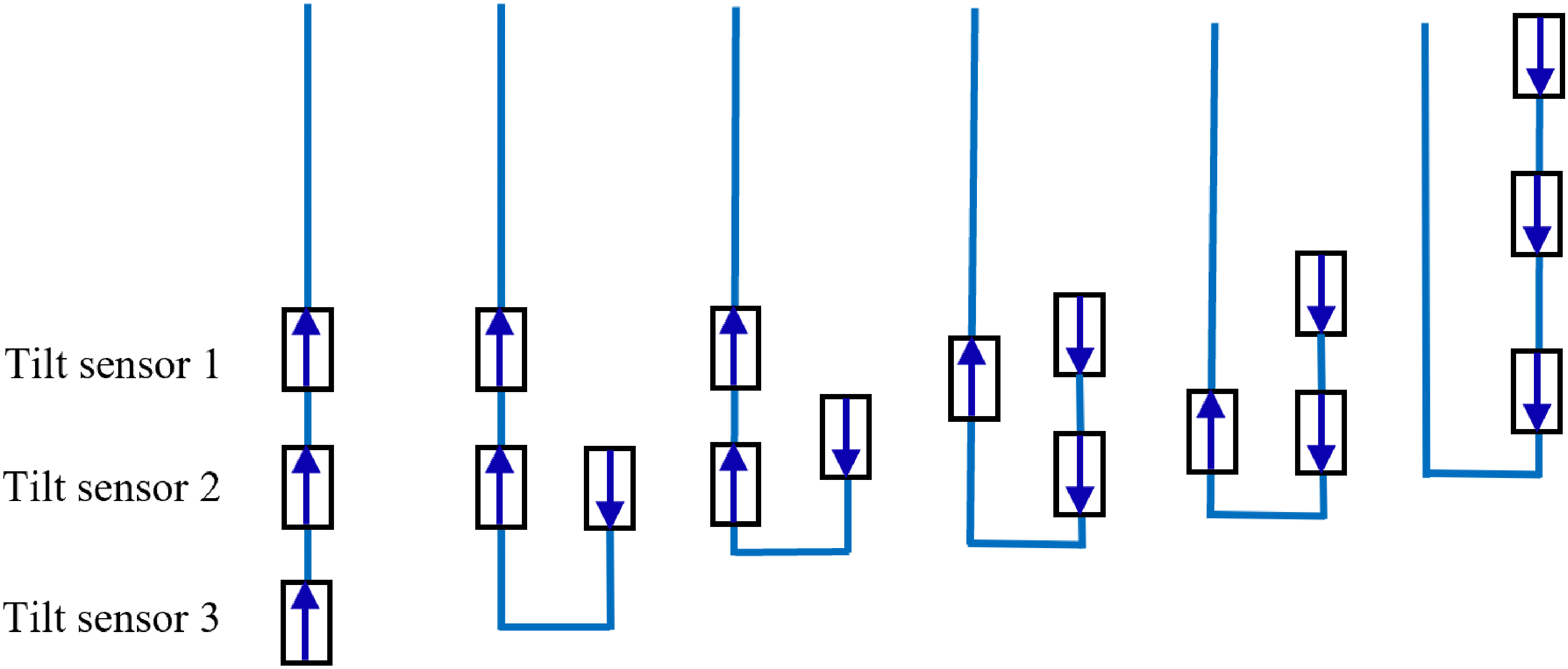
The states of the tilt sensors are as shown in Figure 10, totaling six valid states.
Schematic diagram of the tilt sensors.

The goal of the proposed velocity-adaptive strategy is to dynamically adjust the robot’s climbing velocity according to the status of the relative-position detection device, thereby maintaining an appropriate and safe relative position between the robot and the worker. As described in Section 3.1, the robot operates under the motion commands issued by the operator, while the proposed controller is responsible only for adaptive climbing-velocity regulation during the climbing process.
After startup, the outer position loop estimates the relative human–robot position from the tilt sensor and updates the target climbing velocity using the proposed velocity-adaptive strategy, while the inner current loop regulates the motor current through the PID controller to ensure stable motor operation under varying load conditions.
Within each control period, the status of the relative-position detection device is read. Based on the robot’s movement direction, the detected relative-position state, and prior knowledge, the target climbing velocity is updated accordingly. The target climbing velocity is modified only when the detected relative-position state changes and is always constrained within the allowable operating range of the robot. According to the detected relative-position state, the target climbing velocity is increased or decreased until the relative position returns to the desired range. This adaptive adjustment is repeated during each control cycle until the relative position falls within a reasonable range.
The proposed controller employs the dual closed-loop control architecture. The outer position loop generates the target climbing velocity using the proposed rule-based velocity-adaptive strategy, while the inner-loop PID controller continuously regulates the motor velocity to track the corresponding reference velocity. During climbing, the reference climbing velocity is constrained within the allowable operating range:
 \begin{equation} v_{\min }\leq v_{r}\leq v_{\max } \end{equation}
where vr denotes the target climbing velocity, and v min and v max denote the allowable minimum and maximum climbing velocities, respectively. Since the target climbing velocity is adjusted only when the relative-position state changes, abrupt velocity variations during state transitions are avoided. Consequently, smooth climbing operation is achieved under different operating conditions. The robustness of the proposed controller is further demonstrated by the experimental results under different payload conditions and external disturbances presented in Section 5.
3.5. Force–position cooperative regulation strategy
A hierarchical control strategy is employed to achieve force–position coordination.
Force control layer: In the force control layer, we calculate the load force in real time based on current sampling. When
 $F \gt F_{max}$
, the overload protection logic is triggered, and soft stop is realized through linear attenuation of the PWM duty cycle at an attenuation rate of 5%/ms; when
 $F \lt F_{min}$
, the system enters the velocity-up mode.
Position control layer: The rate of change of relative displacement is detected by an array of tilt sensors (three-axis switch sensors). When the displacement deviation exceeds ±5 cm, velocity-adaptive adjustment is initiated.
Force–position collaboration layer: Based on the interaction among eccentric angle, force, and velocity, adjustment rules are established: when F increases and v decreases, the eccentric angle is reduced to enhance force output; when F decreases and v exceeds the target value by 15%, the eccentric angle θ is increased to reduce driving power. The relationship between sensor states and velocity adjustment is shown in Table IV.
The relationship between the status of the tilt sensor and velocity regulation.

Table IV. Long description
A table with three columns and three rows. The columns are labeled Sensor status, Relative velocity direction, and Adjustment strategy. Row 1: Sensor status, 001; Relative velocity direction, Robot is faster than the worker; Adjustment strategy, Slow down by 10 percent. Row 2: Sensor status, 010; Relative velocity direction, Synchronization; Adjustment strategy, Maintain the current velocity. Row 3: Sensor status, 100; Relative velocity direction, The worker is faster than the robot; Adjustment strategy, Growth rate: 15 percent.
3.6. Adaptive PID parameter tuning
In response to changes in control characteristics under different load conditions, a PID parameter adaptive adjustment mechanism is designed.
Load force zoning: The load force is divided into three zones: light load (F< 40 N), medium load (40 N ≤ F ≤ 60 N), and heavy load (F> 60 N).
Parameter table mapping: The optimal PID parameters are obtained for each interval through offline experiments.
Light load zone: KP = 15, KI = 1.2, KD = 2;
Medium load zone: KP = 12, KI = 0.8, KD = 3;
Heavy load zone: KP = 8, KI = 0.5, KD = 4;
Dynamic correction factor: A correction factor α is introduced to perform real-time fine-tuning of the PID parameters, which is defined as:
 \begin{equation} \alpha =1+\beta \left(F-F_{ref}\right) \end{equation}
The real-time fine-tuning rules for the PID parameters are expressed as:
 \begin{equation} KP^{*}=KP\cdot \alpha \end{equation}
 \begin{equation} KI^{*}=KI\cdot \alpha \end{equation}
 \begin{equation} KD^{*}=KD\cdot \alpha \end{equation}
3.7. Experimental verification and performance analysis
In the 10 m T-shaped guide rail experiment, when the load force jumps from 30 N to 70 N, the response of the force–position cooperative algorithm is as follows:
When the current rises from 1.8 A to 4.2 A, the force estimation error is less than 3%.
The eccentricity angle automatically decreases from 30° to 25°, and the velocity fluctuation range is less than 4%.
After dynamic adjustment of PID parameters, the system regulation time is less than 0.5 s and the overshoot is less than 8%. The force–position cooperative control accuracy under different loads is shown in Table V.
The accuracy of force–position cooperative control under different loads.

Table V. Long description
A table titled ‘The accuracy of forceposition cooperative control under different loads’ with four columns and three rows. The columns are labeled ‘Load (N)’, ‘Force control error (%)’, ‘Velocity control error (%)’, and ‘Adjustment time (ms)’. The rows present data for loads of 30 N, 50 N, and 70 N. Row 1: Load (N), 30; Force control error (%), 2.1; Velocity control error (%), 1.3; Adjustment time (ms), 350. Row 2: Load (N), 50; Force control error (%), 1.8; Velocity control error (%), 2.8; Adjustment time (ms), 420. Row 3: Load (N), 70; Force control error (%), 2.5; Velocity control error (%), 4.4; Adjustment time (ms), 480.
3.8. Velocity coordination analysis for human–robot cooperative climbing
The performance of the proposed human–robot cooperative climbing assistance strategy is illustrated through the velocity coordination between the user and the robot, as shown in Figure 11. The control objective is not exact trajectory tracking; instead, the robot adjusts its climbing velocity to maintain a safe relative position and provide stable assistive support during climbing.
The robot follows the functional velocity curve.

3.8.1. Acceleration phase
The velocity of the operator initially exceeds the following velocity of the device. After a response delay of several milliseconds, the device begins to accelerate and follow the operator within about 0.5 s. The following velocity curve shows smaller fluctuations than the velocity curve of the operator. The intentional lag enhances operational safety and results from motor command inertia and the need to overcome load inertia from rest.
3.8.2. Constant velocity phase
After approximately 5 s, the velocity of the operator stabilizes around 0.6 m/s. A transient peak in the velocity of the device at this moment reflects natural acceleration fluctuations during stabilization, yet the device maintains an overall smoother velocity profile.
3.8.3. Deceleration phase
As the operator slows down, the velocity of the device decreases with a similar but slightly delayed rhythm. Both curves decline gradually toward a lower steady-state value.
Overall, the velocity profile of the device during both ascent and descent is notably smoother and more linear than that of the operator. This is due to the control system’s consistent effort to maintain a steady target velocity, which ensures the delivery of a stable auxiliary force. As a result, the system effectively reduces the operator’s physical exertion, even when faced with velocity variations caused by fatigue or changes in climbing rhythm.
3.9. Control flowchart
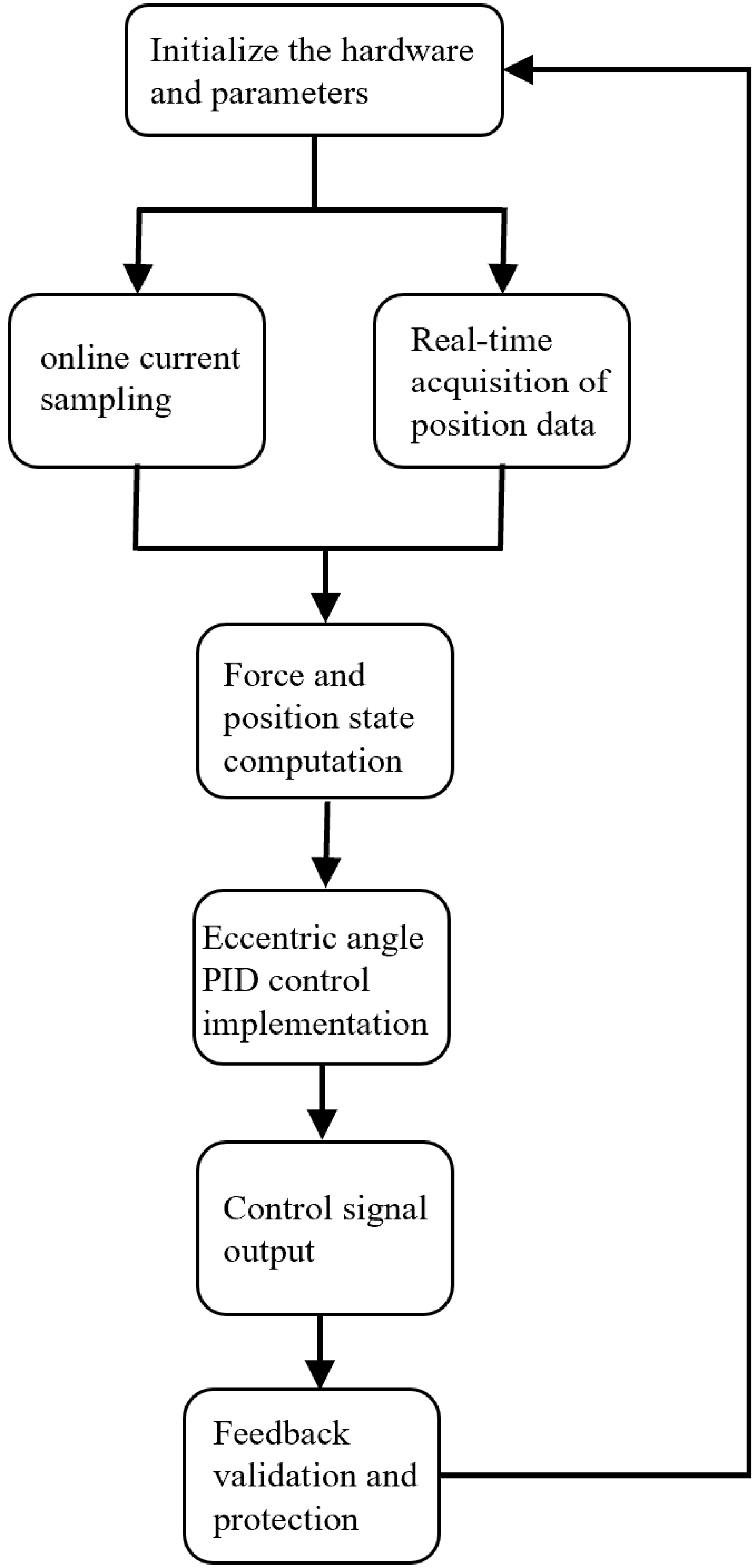
This algorithm realizes the coordinated adaptive adjustment of load force and position during the climbing process through a closed-loop process of hardware sampling, mechanical modeling, logical judgment, and control output, ensuring the stability and safety of the system under different working conditions. The algorithm execution process is illustrated in Figure 12.
Algorithm execution process.

4. ADAMS simulation analysis
4.1. Contact modeling and simulation framework
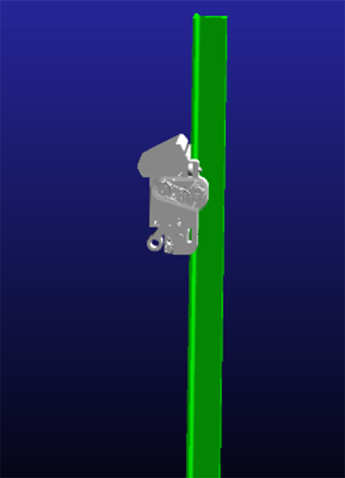
Dynamic simulation of the robot was performed using Automatic Dynamic Analysis of Mechanical Systems (ADAMS) dynamics software to investigate the variation trends of motor torque and angular velocity during its movement along vertical T-shaped guide rail surfaces. Contact modeling between the robot assembly, the T-shaped guide rail, and the climbing surface was implemented in ADAMS, as illustrated in Figure 13. The contact model enables the prediction of wheel–rail interaction forces, friction effects, and impact phenomena during climbing, thereby providing the basis for evaluating the dynamic behavior of the proposed robot.
Schematic diagram of robot motion simulation.

4.2. Motor torque and angular velocity during climbing
To investigate the motor dynamic characteristics during the robot’s ascent, directional reversal, and descent phases, the simulated torque and angular velocity profiles were extracted, with the corresponding results presented in Figure 14. This figure depicts the motor torque variation (green curve) and angular velocity profile (blue curve), where positive/negative angular velocity values denote clockwise/counter-clockwise motor rotation, respectively.
Simulated angular velocity and torque responses during robot climbing.

Ascending motion (0–3 s):
The motor starts at t = 0 s, with the rotor initially at rest. To overcome the initial inertial load, both motor torque and angular velocity surge rapidly to their peak values during startup. After this transient peak phase, the system enters a steady operating state: the motor torque stabilizes at approximately 0.22 N · m, providing the driving torque required for steady climbing. The angular velocity remains steady at +445 deg/s, ensuring a constant-velocity ascent of the robot.
Directional reversal (3–3.4 s):
The control command reverses the motor rotation to initiate braking. This induces an abrupt change in the direction of the wheel-rail contact force, while the driving torque and wheel angular velocity drop sharply, enabling the system to decelerate and reverse its motion direction.
Descending motion (3.4–7 s):
Post-reversal, torque and angular velocity rapidly stabilize. During controlled descent, angular velocity is sustained at −450 deg/s (± 2% fluctuation). The motor mainly provides a braking torque, which stabilizes at approximately 0.05 N · m.
4.3. Characteristics of wheel contact forces
To further investigate the dynamic interaction between the robot and the vertical T-shaped guide rail during locomotion, the contact force profiles of the robot’s wheels were simulated and analyzed, with the results presented in Figure 15. Three curves denote contact forces: blue (mid-mounted drive wheel), green (right drive wheel), and purple (left drive wheel).
Simulated wheel–rail contact force responses during robot climbing.

Initial motion (0–0.5 s)
During inertial torque startup, all wheels exhibit significant contact force oscillations due to static equilibrium overcoming and dynamic stability establishment. As the primary load-bearing component, the mid-mounted drive wheel – being proximal to the center of mass (COM) and subjected to the maximum dynamic load – exhibits the largest contact force fluctuation amplitude, with a peak value of F max = 48 N. The left driving wheel has a peak contact force of F max = 33 N, while the right driving wheel has a peak contact force of F max = 35 N.
Ascending motion (0.5–3 s)
During ascent, left and right drive wheels display congruent contact force trends with minimal fluctuation (mean F = 26.8 N). In contrast, the mid-mounted drive wheel shows amplified oscillations (mean F = 37.4 N) due to its single-point support geometry and overturning moment effects, reflecting dynamic adjustments for vertical alignment against gravity and guide rail irregularities.
Directional transition (3–3.5 s)
During braking and descent initiation, the counter-torque generated by motor reversal couples with gravity, triggering an instantaneous surge in the contact forces of all wheels and thus significantly elevating the peak stresses at the wheel-rail interfaces and component joints.
Descending motion (3.5–7 s)
After the robot completes the turnaround operation, the front–rear positional layout of the mid-mounted drive wheel and the left/right drive wheels are swapped. The mid-mounted drive wheel sustains significantly higher forces (mean F = 68.4 N) with pronounced oscillations, while left/right drive wheels show attenuated variations (mean F = 41 N) with minimal fluctuations.
5. Experimental results and discussion
5.1. Prototype performance evaluation
To verify the climbing performance and anti-fall capability of the proposed robot under practical operating conditions, a prototype experiment was conducted on a T-shaped guide rail. As shown in Figure 16, the robot completed a continuous sequence of ascent, smooth turnaround, and descent along a 1 m guide rail. Throughout the experiment, no falling, severe slipping, or instability was observed, indicating that the proposed three-point clamping mechanism maintained continuous wheel–rail engagement and sufficient attachment force during the entire climbing process.
Robot’s locomotion during T-shaped guide rail climbing.

During the prototype experiment, the climbing direction, as well as the commands for motion initiation, stopping, and reversal, were manually issued by the operator, whereas the proposed controller continuously regulated the robot’s climbing velocity throughout the climbing process.
Throughout the climbing process, the robot exhibited stable motion during both upward and downward travel. During the 0–3 s interval, the robot climbed upward at an approximately constant velocity. Between 3.0 s and 3.5 s, the robot smoothly completed the transition from upward to downward motion following the operator’s reversal command. Afterward, the robot descended steadily until the end of the experiment. The vertical displacement before and after the turning process differed by less than 5 cm, indicating that the robot completed the braking and direction transition rapidly without noticeable position drift. These observations demonstrate the stable dynamic characteristics of the proposed mechanism during continuous climbing and turning.
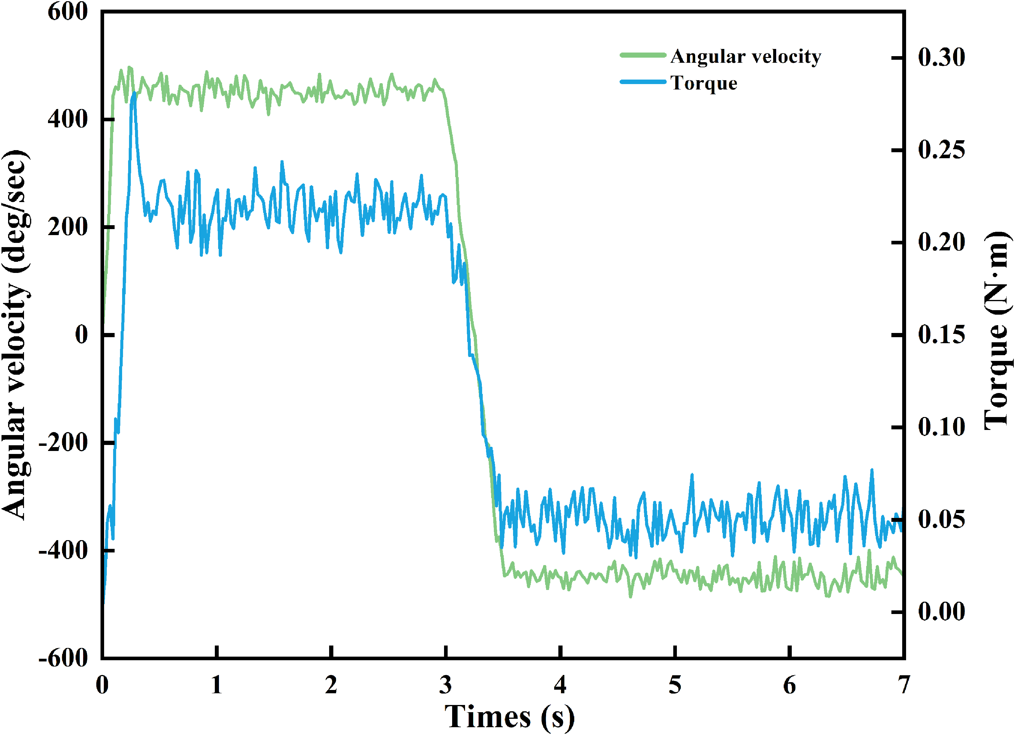
To further evaluate the dynamic behavior of the proposed system, the angular velocity, torque, and contact force responses are presented in Figures 17 and 18. The experimental responses exhibit dynamic trends that are generally consistent with the simulation throughout the climbing and turning processes. During steady climbing, the angular velocity remained close to the simulated value, with fluctuations of approximately ± 4% around the nominal velocity, while the driving torque stabilized at approximately 0.21 N · m following an initial startup peak of approximately 0.28 N · m. The transition between upward and downward climbing was completed within approximately 0.5 s in both the simulation and the experiment, indicating a rapid and stable dynamic response.
Angular velocity and torque responses during climbing and direction reversal.

Wheel–rail force responses during robot climbing.

For the wheel–rail contact forces, the mid-mounted drive wheel maintained a steady contact force of approximately 68–71 N, whereas the left and right drive wheels both stabilized at approximately 41 N. The contact force responses of the two side wheels almost completely overlapped throughout the experiment, indicating that the three-point clamping mechanism achieved a nearly symmetric load distribution on both sides of the guide rail. Compared with the idealized ADAMS simulation, the experimental responses exhibited moderate fluctuations caused by practical wheel–rail interaction and other operating disturbances. Nevertheless, the fluctuation amplitudes remained limited, and no abrupt force interruption or loss of wheel–rail contact occurred during the entire climbing process.
Overall, the experimental observations agree well with the ADAMS simulation in terms of steady-state angular velocity, driving torque, wheel–rail contact force distribution, and motion transition characteristics. These results demonstrate that the proposed mechanical design can achieve stable and reliable climbing on T-shaped guide rails under practical operating conditions.
5.2. Experimental evaluation under different payload conditions
To further evaluate the robustness of the proposed mechanism under different loading conditions, experiments were conducted using payloads of 2 kg and 4 kg, respectively. The corresponding experimental setups are shown in Figure 19.
Experimental setups under different payload conditions: (a) 2 kg payload and (b) 4 kg payload.

The wheel–rail contact forces of the three wheels during the climbing process are presented in Figure 20.
Wheel–rail contact force responses under different payload conditions: (a) 2 kg payload and (b) 4 kg payload.

As shown in both figures, the contact forces increase rapidly during the initial acceleration stage and gradually converge to stable values after approximately 0.6 s. Comparing the two payload conditions, the overall contact force distribution pattern remains essentially unchanged, whereas the steady-state contact forces increase slightly with increasing payload. Under both loading conditions, the middle driving wheel consistently bears the largest contact force, while the left and right driving wheels exhibit nearly identical responses, indicating that the proposed three-point clamping mechanism maintains a balanced load distribution during climbing.
Compared with the 2 kg payload, the average contact force of the mid-mounted drive wheel increases by approximately 6–8%, whereas the increases of the two side wheels are relatively small. In addition, the 4 kg payload exhibits slightly larger steady-state force fluctuations than the 2 kg payload, reflecting the increased dynamic load transfer associated with the heavier external load. Nevertheless, the fluctuation amplitudes remain limited, and no abrupt force loss, excessive local force concentration, or unstable wheel–rail contact is observed throughout the experiments. These results demonstrate that the proposed mechanism can automatically redistribute the wheel–rail contact forces in response to different payloads while maintaining continuous rail engagement and stable force transmission.
5.3. Experimental evaluation under external disturbances
During the climbing process, transient downward external disturbances were manually introduced to simulate temporary variations in the user’s climbing velocity relative to the robot. The resulting changes in the relative inclination were detected by the tilt sensor-based relative-position detection device. The experimental procedure is illustrated in Figure 21. In response to the detected changes in the relative inclination, the robot automatically adjusted its climbing velocity, thereby adaptively redistributing the wheel–rail contact forces and rapidly restoring stable climbing operation.
External-disturbance experiment during climbing: (a) initial climbing state; (b) downward external disturbance simulating a temporary reduction in the user’s climbing velocity relative to the robot; and (c) recovery to stable climbing operation.

The corresponding wheel–rail contact force responses are presented in Figure 22. When the downward external disturbance was applied, the wheel–rail contact forces increased temporarily, with the mid-mounted drive wheel rising from approximately 41 N to 50 N and the two side wheels increasing from approximately 28 N to 34 N. After the external disturbance was removed, the proposed velocity-adaptive controller continuously adjusted the climbing velocity according to the detected relative inclination, and the wheel–rail contact forces gradually returned to their steady operating levels.
Wheel–rail contact force responses during the external-disturbance experiment.

These results demonstrate that the tilt sensor-based velocity-adaptive strategy enables the robot to continuously regulate the contact force distribution in response to variations in the relative climbing state, thereby maintaining stable climbing operation under temporary external disturbances.
6. Conclusions
This paper presented the structural design, force–position cooperative control framework, and experimental validation of a rail-guided climbing robot for transmission-tower climbing assistance. By integrating a self-balancing eccentric anti-fall mechanism with a multi-stage compound transmission system, the proposed robot achieves stable wheel–rail engagement, adaptive assistive support, and reliable anti-fall performance during climbing on T-shaped guide rails. The mechanical design establishes a robust foundation for safe and reliable human–robot cooperative climbing assistance under varying operating conditions.
To further enhance operational adaptability and safety, a force–position cooperative control strategy was developed, combining a velocity-adaptive strategy with a closed-loop PID velocity controller. The proposed controller continuously regulates the climbing velocity according to the detected relative human–robot position, thereby maintaining a safe interaction distance. By coordinating assistive support force regulation with relative-position maintenance, the proposed control framework ensures stable wheel–rail engagement and smooth climbing operation under varying operating conditions. This approach effectively reduces the risk of slippage and falling during high-altitude operations while improving climbing efficiency.
Both simulation and experimental results validate the effectiveness of the proposed design. ADAMS dynamic simulations demonstrate that the robot maintains stable bidirectional motion on the T-shaped rail. During ascent, the steady-state motor torque is approximately 0.22 N · m at a constant angular velocity of + 445 deg/s, with the mean contact forces of the central wheel and the side driving wheels being 37.4 N and 26.8 N, respectively. Prototype experiments exhibited good agreement with the simulation results. Furthermore, experiments conducted under different payload conditions and external disturbances demonstrated stable wheel–rail contact-force distribution and rapid recovery after temporary disturbances, confirming the load adaptability and robustness of the proposed system. The robot successfully completed continuous cycles of ascent, turnaround, and descent on the test rail, demonstrating reliable anti-fall performance and stable human–robot cooperative climbing assistance.
Although this study primarily focused on mechanical optimization and motion/control strategies under nominal conditions, the proposed architecture provides a flexible framework for future extension. Its underlying principles are not limited to vertical rail climbing and can be adapted to a broader range of climbing and inspection scenarios. Future work will investigate the robot’s performance under extreme environmental conditions, such as strong winds, icing, heavy rain, and temperature extremes, as well as long-term durability and field deployment on complex transmission tower structures.
Overall, the proposed rail-guided climbing robot establishes an effective mechanical and control framework for safe human–robot cooperative climbing assistance and demonstrates considerable potential for transmission-tower inspection, maintenance, and other high-altitude industrial applications.
Author contributions
Xiang Yue carried out Conceptualization, Formal analysis, and Writing – original draft, and Review/editing. Zhiyu Chen, Yan Xu, and Fuxing Wang performed Conceptualization, Formal analysis, Mathematical model derivation, Writing – original draft, and Review/editing. Haoyu Hua and Rui Wang conducted data gathering and data processing. Hua Gao performed review.
Financial support
This research was funded by the Scientific Research Foundation of Education Department of Liaoning Province (LJ212510157012).
Competing interests
The authors declare no conflicts of interest exist.
Ethical approval
Not applicable.