Introduction
Point-of-care (POC) assays are used for detecting analytes in environments that lack laboratory infrastructure.Reference Gubala, Harris, Ricco, Tan and Williams 1 Quantitative POC assays are more challenging to perform than qualitative assays, yet they provide the most detailed—and oftentimes essential—diagnostic information (e.g., glucometers). Traditional approaches to quantitative POC assays are not suitable for use in remote villages, and therefore new technologies are needed.Reference Yager, Edwards, Fu, Helton, Nelson, Tam and Weigl 2 – Reference Yager, Domingo and Gerdes 6
New materials that simplify standard POC chemistry will enable assays that are ideally suited to the most resource-poor environments in the world without compromising sensitivity and selectivity. Such a simplification can be achieved by (1) developing appropriate detection and signal amplification reagents, (2) designing inexpensive and readily available assay platforms, and (3) advancing batteries and electronics with a focus on low cost and simplicity of operation. Progress in these three areas requires close collaboration between organic and analytical chemists as well as materials scientists, with guidance from medical practitioners. Creative advances in materials chemistry also may enable entirely new types of quantitative POC assays that circumvent the tenets of traditional analytical chemistry; we will show one example of this type.
This overview is organized by features that are common in traditional quantitative POC assays, with a focus on new materials (such as paper that is patterned into hydrophilic microfluidic channels) that enable low-cost assays while still maintaining performance. Other materials in this context include micron-thick squares of metal electrodes embedded in paper, paper coated with paraffin wax, and organic materials coated onto paper that switch from hydrophobic to hydrophilic in response to specific analytes. The examples presented are primarily from our work, but other articles in this issue and published reviewsReference Weigl, Domingo, LaBarre and Gerlach 7 – Reference Zhao and van den Berg 10 provide summaries of alternative and often complementary approaches.
Defined sample volume
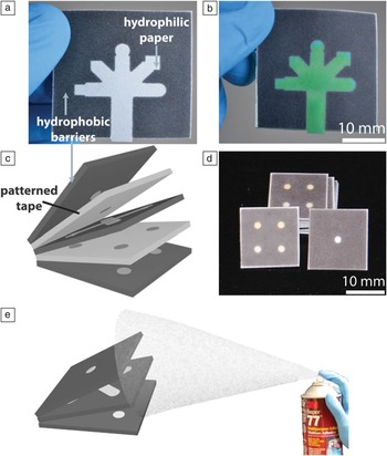
Fixed volumes of sample are needed in quantitative assays to normalize the number of molecules of analyte in a sample that are exposed to the assay reagents. One of the most straightforward methods for obtaining a fixed volume of sample is to use (or create) an absorbent material that holds a defined quantity of sample when wet. In 2007, Whitesides and colleagues demonstrated that paper (an abundant and absorbent material) could be used for this purpose when the paper is patterned into defined hydrophilic and hydrophobic regions. This process creates microfluidic channels in paper, where the hydrophobic paper confines a sample into the hydrophilic channels ( Figure 1 a–b).Reference Martinez, Phillips, Butte and Whitesides 11 , Reference Lu, Shi, Jiang, Qin and Lin 15 , Reference Carrilho, Martinez and Whitesides 16 These channels absorb relatively fixed volumes of water and are capable of distributing a single sample (by capillary action) into multiple discrete regions where separate assays take place (appropriate assay reagents are pre-deposited into the assay regions prior to wicking the sample into the device). This clever approach to sample distribution and control of sample volume eliminates the need for auxiliary pipettes or other means of delivering a fixed volume of sample to an assay platform.
Examples of paper-based microfluidic devices. (a) A two-dimensional (2D) device with a hydrophilic channel (white), five assay regions (arms extending from the central channel), and hydrophobic wax (gray) patterned into paper.Reference Lu, Shi, Jiang, Qin and Lin 15 , Reference Carrilho, Martinez and Whitesides 16 (b) Device from (a) in which the hydrophilic channel is filled with aqueous green food coloring. (c) Depiction of a 3D paper-based microfluidic device that is made from alternating layers of wax-patterned paper and patterned double-sided adhesive tape.Reference Martinez, Phillips and Whitesides 12 (d) Photographs of devices from (c). The devices are 20 mm wide × 20 mm long × 0.5 mm thick. (e) A method for fabricating 3D paper-based microfluidic devices using spray adhesive.Reference Lewis, DiTucci, Baker and Phillips 13

The concept of paper-based microfluidic devices has been extended to three dimensions (3D)Reference Martinez, Phillips and Whitesides 12 either by stacking layers of patterned paperReference Lewis, DiTucci, Baker and Phillips 13 , Reference Liu and Crooks 14 or by alternating layers of paper and tapeReference Martinez, Phillips and Whitesides 12 (Figure 1c–e). These 3D devices have become our preferred platform, primarily because they enable fluid movement in three dimensions, which substantially increases the number of assays that can be incorporated into a device of a defined size while still minimizing the volume of sample that is needed for the assay(s).
Controlling the duration of an assay
Fixed assay times are a hallmark of quantitative POC assays. The vast majority of quantitative POC assays (and even qualitative assays) require a timer to ensure that the signal from the assay is measured after a defined time period. A timer, however, is an extra piece of equipment that adds cost and ultimately complicates the execution of an assay.
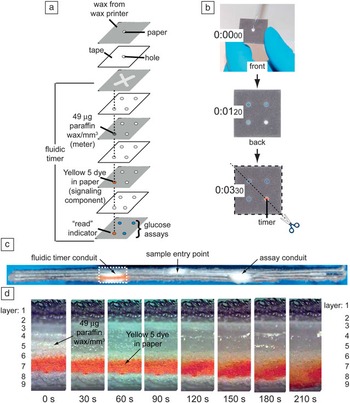
To circumvent the need for external timers, we recently developed strategies for fabricating timers directly into 3D paper-based analytical devices ( Figure 2 a–d).Reference Noh and Phillips 17 , Reference Noh and Phillips 18 These timers operate by splitting a sample into multiple hydrophilic conduits in the microfluidic device, several of which proceed to regions where assays take place, and one of which proceeds through a layer of paper that contains picomole quantities of paraffin wax (Figure 2a). This wax alters the wetting properties of the paper in a predictable way, and as a result, we can precisely control the time required for the sample to pass through this conduit relative to the time required for the sample to reach the assay regions. In fact, by simply changing the quantity of wax in the timer conduit, we have made a variety of timers that measure time periods of 1 min up to 1 h with 30 s intervals along this range. We found that these internal “fluidic timers” provide more accurate results for quantitative colorimetric assays than comparable assays in which an external timer was used;Reference Noh and Phillips 18 this improved performance is achieved because changes in environmental conditions that would affect sample distribution in a paper-based microfluidic device (such as humidity and temperature) will also alter the paper-based timer. Such changes cannot be easily corrected for using an external timer.
Example of a fluidic timer. This particular timer is built into a 3D paper-based microfluidic device. (a) The 3D paper-based device runs an assay (in triplicate) for measuring the level of glucose in a sample. The dotted lines indicate the conduit for the fluidic timer. (b) Demonstration of the function of the fluidic timer. The orange circle that appears at 3 min 30 s is the indicator feature of the fluidic timer; it signals the endpoint of the assay. The blue circles show the results of a positive assay for glucose. (c) Cross-section of the fluidic timer shown in (b). The diagonal dotted line in (b) denotes where the device was cut for the cross-section. The width of the cross-section in the image is 28.2 mm. (d) Expanded view of the boxed region of the cross-section shown in (c). The paraffin wax meter is in the fifth layer. Yellow 5 is in the seventh layer and is the dried food coloring that indicates the endpoint of the fluidic timer when it re-dissolves in the sample and is wicked to layer 9, where the color becomes visible. The expanded view shows the time-lapsed distribution of 5 μL of ddH2O through the cross-section of the fluidic timer. The cross-section images were taken using a Zeiss Axiovert 200 microscope with 4× magnification. Adapted with permission from Reference 18. © 2010 American Chemical Society.

Power supply
Fluorescent, electrochromic, and electrochemiluminescent assays are all standard quantitative POC assays that require power for conducting the assay. In the most resource-limited environments, standard batteries pose challenges in terms of cost, disposal issues, uncertainty as to the remaining charge, and the requirement that the user transfer the battery from one assay device to another. An alternative strategy involves creating batteries that are incorporated directly in the microfluidic channels of a paper-based microfluidic device.Reference Thom, Yeung, Pillion and Phillips 19 , Reference Liu and Crooks 20 In a recent study, we fabricated batteries from simple galvanic cells that are linked in series and/or parallel as needed to generate power when the sample is added to the microfluidic device.Reference Thom, Yeung, Pillion and Phillips 19 These internal “fluidic batteries” use AgNO3 and AlCl3 electrolytes deposited into defined regions of paper, and ∼180 μm-thick sheets of silver and aluminum electrodes in contact with the electrolyte regions. These batteries generate just enough power to run the associated function for the duration of the assay. They also minimize hazardous waste, since each device requires only microgram quantities of metals and metal salts.
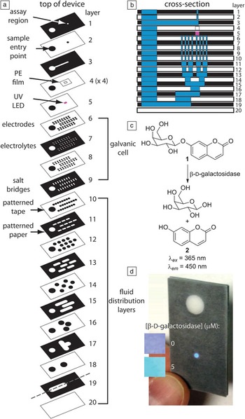
Fluidic batteries function as follows ( Figure 3 a–d). Upon addition of the sample, the internal hydrophilic channels of paper direct the fluid both to the assay region (where, for example, a fluorescence assay occurs) and to the fluidic battery (Figure 3a–b), where power is generated to run a UV LED for the fluorescence assay (Figure 3c–d).Reference Thom, Yeung, Pillion and Phillips 19 Power is generated when the sample re-dissolves the electrolytes in the linked galvanic cells, thus initiating the half-reactions when the electrolyte solutions contact the metal electrodes.
A fluorescent assay on a paper-based microfluidic device that contains a fluidic battery.Reference Thom, Yeung, Pillion and Phillips 19 (a) Expanded view of the device, which contains an inlet for a sample, and a readout region that emits 450-nm light if the analyte is in the sample. The fluidic battery powers an integrated surface-mount UV LED that illuminates the assay region. (b) Cross-section of the device in (a) showing the distribution of sample (blue) within one section of the device. The location of the cross-section is depicted in layer 19 in (a). (c) Reagent 1 is pre-deposited into the assay region prior to assembling the device. Reagent 1 selectively detects β-D-galactosidase through an activity-based detection event that releases 7-hydroxycourmarin (2). Reagent 1 is not fluorescent, whereas 2 is highly fluorescent. (d) The “colorimetric” output provided by the on-chip fluorescence assay is a function of the concentration of β-D-galactosidase in the sample. The assay time was 19 min in all images. The 5-μM inset is an expanded view of the assay region in the larger photograph. Reprinted with permission from Reference 19. © 2012 Royal Society of Chemistry.

Current configurations of fluidic batteries are predictable and highly tunable, and are capable of generating open-circuit voltages equal to an 8 V battery.Reference Thom, Yeung, Pillion and Phillips 19 Ongoing efforts are focused on (1) expanding the range of electrodes and electrolytes that are compatible with this type of battery, as well as (2) simplifying the methods for fabricating these fluidic batteries so that they are smaller, require fewer layers of paper, and can be incorporated routinely and predictably into a variety of paper-based diagnostic devices.
Handheld readers
Essentially all current quantitative POC assays require a measurement using a handheld instrument to enable the quantitative readout. Examples include electrochemical, absorbance, transmittance, and fluorescence readers. More recently, camera-equipped mobile phones have gained attention as a “reader” for reflectance measurements in remote locations.Reference Martinez, Phillips, Carrilho, Thomas, Sindi and Whitesides 21 The process involves photographing the assay using a mobile phone camera and then sending the image to an off-site technician/physician for analysis. The physician then suggests an appropriate treatment to the technician in the field. Substantial challenges remain in this area, including ensuring that variations in external lighting, camera quality, and image quality do not affect the quantitative outcome of a mobile phone-based assay. Inclusion of materials into the analytical platform that enable calibration of the images and that compensate for image quality may offer one route to improving the precision of mobile phones as readers.
Unconventional approaches to quantitative POC assays
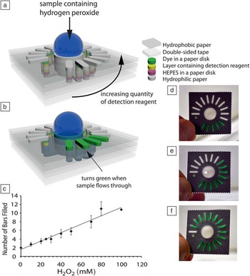
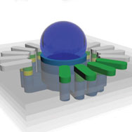
One of the greatest challenges for the materials community is to invent methods for instrument-free quantitative POC assays. We recently demonstrated one approach to achieving this goal that only requires the user to see color and count,Reference Lewis, DiTucci and Phillips 22 which is a dramatic departure from traditional quantitative POC assays. In this assay, fixed sample volumes, power supplies, and external readers are not needed; instead, the assay is based on the ability to control the flow of sample through paper in a way that depends both on the presence and concentration of a specific analyte ( Figure 4 ). This assay uses 3D paper-based microfluidic devices (Figure 4a–b) and fixed assay times, and at the end of the assay, the user quantifies the level of an analyte by simply counting the number of colored bars that appear on top of the device (Figure 4c–f). In these assays, the paper in each outer conduit (i.e., column of hydrophilic paper; Figure 4a) has been modified with a hydrophobic small molecule reagent (yellow layer in Figure 4a) that reacts with a desired analyte (this reaction provides selectivity for the assay). This reaction switches the small molecule from hydrophobic to hydrophilic, and thus changes the wetting properties of the paper on which it is adsorbed from hydrophobic to hydrophilic. In the absence of the analyte, the hydrophobic reagents prevent the sample from traveling through the conduits, but in the presence of the analyte, the sample passes through the yellow selection layer in Figure 4a and continues wicking (by capillary action) in the z-direction toward the top of the device. Prior to reaching the top hydrophilic bar-shaped regions, the sample re-dissolves dried food coloring (green layer in Figure 4a) that provides an unambiguous color when the sample disperses over the bars on the top of the device (Figure 4b). To render this assay quantitative, each outer conduit (in a counterclockwise direction) contains increasing quantities of the hydrophobic compound that reacts with the analyte (Figure 4a). Well-defined kinetics of the reaction between the analyte and the hydrophobic small molecule suggest that a fixed time assay should enable a quantitative measurement of the analyte by simply counting the number of bars that turn green on the top of the device (Figure 4c–f).
A strategy for quantifying analytes by counting. (a) Design of the 3D paper-based device. (b) Demonstration of the distribution of the sample (blue) within the device. The green bars appear when the analyte reacts with the detection reagent (yellow) and completely flows through the conduit. (c) The quantity of an analyte (in this case, hydrogen peroxide) is measured by counting the number of green bars after a fixed assay time. In (c), the assay time was 10 min. (d–f) Photographs of devices that were exposed to (d) 1 mM, (e) 75 mM, and (f) 100 mM hydrogen peroxide after a 10-min assay. These devices used a smaller quantity of the detection reagent per conduit than the devices in (c). The dimensions for the devices are 32 mm wide × 32 mm long × 1.0 mm thick. Reprinted with permission from Reference 22. © 2012 Wiley-VCH Verlag GmbH & Co. KGaA, Weinheim.

In one proof-of-concept assay, hydrogen peroxide was quantified over a range of 10–100 mM (Figure 4c).Reference Lewis, DiTucci and Phillips 22 In this type of system, dramatic improvements in selectivity and sensitivity should be possible with appropriate advances in materials chemistry that (1) expand the scope of possible analytes, and (2) enable amplified changes in wetting properties when the analyte is present. Extensions of this approach to quantitative enzyme assays are forthcoming.
Conclusions
The development of quantitative point-of-care (POC) diagnostics for use in extremely resource-limited environments is evolving quickly, driven primarily by new assay platforms (e.g., paper microfluidics) and new approaches in materials science that balance simplicity with surprisingly complex and useful functions. Often missing from discussions about quantitative POC assays are the reagents that are essential for the assays. Refrigeration is lacking in extremely resource-limited settings, and temperatures are often high, which limits the usefulness of standard detection and signal amplification reagents such as antibodies, nucleic acids, and enzymes. As such, this area would benefit substantially from new technologies for stabilizing standard reagents,Reference Stevens, Petri, Osborn, Spicar-Mihalic, McKenzie and Yager 23 as well as from entirely new small molecule and polymer detection and signal amplification reagents that are designed to be stable at elevated temperatures. These reagents ideally would possess all of the following characteristics: (1) detect a particular analyte selectively,Reference Cho and Sessler 24 (2) provide an unambiguous readout at the end of the assay,Reference Mohapatra and Phillips 25 and (3) amplify either the analyte or signal to enable trace-level detection.Reference Baker and Phillips 26 – Reference Yeung, Schmid and Phillips 28 Developing new thermally stable reagents for detection and signal amplification is an emerging area of researchReference Scrimin and Prins 29 that would benefit from increased synergistic development of assay platforms (such as paper-based microfluidics) and the reagents. An example of such a co-development is shown in Figure 4.Reference Lewis, DiTucci and Phillips 22
The challenge of creating simple, yet high-performance quantitative POC assays is clearly motivating the development of new science that may have a useful impact well beyond the developing world, including in emergency rooms, emergency situations, at home (for home health care), in inner city clinics, in military settings, and in a variety of other settings.
Acknowledgments
The material in this overview is based on work supported by the Bill and Melinda Gates Foundation, the Arnold and Mabel Beckman Foundation, the Camille and Henry Dreyfus Foundation, 3M, the Alfred P. Sloan Research Fellows program, Louis Martarano, and The Pennsylvania State University.