1 Introduction
Similarity solutions play an important role in fluid mechanics. When a self-similar solution exists, it enables variables in the governing equations to be combined into new ones, and the number of variables is reduced as a result. It becomes particularly effective when a partial differential equation becomes an ordinary one or an unsteady problem becomes steady in the self-similar variables. In some cases, such a transformation allows an explicit form of the solution of the problem to be obtained, or the solution procedure to be significantly simplified. The result can then provide some real insights into the physics of the problem. Self-similar solutions have been obtained in a wide range of fluid flow problems. One typical example is the flow inside a boundary layer Batchelor (Reference Batchelor1967, p. 188). Pullin (Reference Pullin1978) obtained a self-similar solution for the roll-up of a semi-infinite vortex sheet and starting flow past an infinite wedge. The latter was confirmed by the experimental study by Pullin & Perry (Reference Pullin and Perry1980). Another well-known example is the explicit solution obtained by Glauert (Reference Glauert1956) for a wall jet. For a free-surface flow, Longuet-Higgins (Reference Longuet-Higgins1976) found self-similar solutions for a variety of free-surface shapes. Zeff et al. (Reference Zeff, Kleber, Fineberg and Lathrop2000) considered jet eruption, while Keller & Miksis (Reference Keller and Miksis1983) considered the coalescence of two liquids driven by surface tension.
For the liquid impact problem, its mathematical modelling is very challenging due to rapid changes of the free-surface shape and velocity in local areas, together with high-speed jets. The pioneering works on the water impact problem based on an impulse solution for a plate were carried out by von Karman (Reference von Karman1929), Wagner (Reference Wagner1932). A complete linearized solution of the water entry of a wedge was first proposed by Mackie (Reference Mackie1962). Garabedian (Reference Garabedian1953, Reference Garabedian and Finn1965), Mackie (Reference Mackie1963), Fraenkel & McLeod (Reference Fraenkel and McLeod1997), Fraenkel & Keady (Reference Fraenkel and Keady2004) extensively studied the main properties of water-entry flows including the existence and uniqueness of similarity solutions and the limit of the contact angle between the free surface and the wedge.
Remarkable progress in the understanding of fluid/structure and fluid/fluid impact phenomena has been achieved over the last decades, which has been based on further development of Wagner’s theory together with the technique of matched asymptotic expansions (Armand & Cointe Reference Armand and Cointe1987; Howison, Ockendon & Wilson Reference Howison, Ockendon and Wilson1991; Howison, Ockendon & Oliver Reference Howison, Ockendon and Oliver2002, Reference Howison, Ockendon and Oliver2004; Korobkin Reference Korobkin2004; Moore et al. Reference Moore, Ockendon, Ockendon and Oliver2015). Different simplified models for the wedge entry problem have also been proposed by Greenhow (Reference Greenhow1987) and Mei, Liu & Yue (Reference Mei, Lui and Yue1999).
In general, water-entry processes are fully transient, and the temporal and spatial variables are fully independent. However, in some cases, especially at the initial stage of impact and/or in some local areas, the flow may be treated as self-similar, which simplifies the analysis and gives some insight into the flow topology during the impact. Examples include those by Cumberbatch (Reference Cumberbatch1960) for a liquid wedge impacting on a flat wall, Dobrovol’skaya (Reference Dobrovol’skaya1969), Zhao & Faltinsen (Reference Zhao and Faltinsen1993) for a symmetric solid wedge entering a calm water surface, Semenov & Iafrati (Reference Semenov and Iafrati2006) for the water entry of an asymmetric wedge, Semenov, Wu & Oliver (2013) (Reference Semenov, Wu and Oliver2013) for an impact between two liquids of the same density, Semenov, Wu & Korobkin (2015) (Reference Semenov, Wu and Korobkin2015) for liquids of different densities and Iafrati & Korobkin (Reference Iafrati and Korobkin2004) for flow near the corner of a horizontal plate impacting a flat surface at the initial stage.
In reality, actual bodies will have only a finite height, beyond which the flow will detach from the body if not earlier. In this case, even the previous self-similar solution before the detachment becomes non-similar because the height of the body enters into the problem as a length scale. Similarly, the water entry of a body of curvature does not admit a self-similar solution either as the radius can be a length scale. Compared with attached flow, there has been far less work on water entry with flow detachment. Limited examples include the water entry of a finite wedge by Zhao, Faltinsen & Aarsnes (Reference Zhao, Faltinsen and Aarsnes1997), Tassin, Korobkin & Cooker (Reference Tassin, Korobkin and Cooker2014) and the impact of a plate onto a flat free surface (Iafrati & Korobkin Reference Iafrati and Korobkin2004). As was shown by Wu & Sun (Reference Wu and Sun2014), if the body is allowed to expand during the water entry, then the flow can be self-similar.
In this paper, we consider the problem of water entry of a wedge/plate whose sides expand at a speed that is in a fixed ratio to the entry speed. The mathematical model and solution procedure are given in § 2. Gravity is ignored based on the assumption that time
 $t$
is much smaller than the ratio of the entry speed to the acceleration due to gravity, and the surface tension effect is ignored. For such a case a self-similar flow becomes possible even with flow detachment. It is obvious that when the wedge expansion speed, considered in § 3.1, is sufficiently large, the liquid on the body surface will not surpass its side and the problem will be identical to the previous self-similar solution for an infinite wedge. As the expansion speed tends to zero, the flow will tend to the steady Helmholtz flow (Gurevich Reference Gurevich1965) with an infinite cavity downstream of the wedge. A self-similar solution for an expanding horizontal flat plate vertically entering a free surface is obtained as a special case of a wedge of half-inner-angle
 ${\rm\pi}/2$
. However, this case differs significantly from the wedge water entry due to the fact that the flow always detaches after the impact, or the flow detachment occurs even at larger or an infinite expansion speed. The obtained solution for water entry of a plate at infinite expansion speed is not unique, as the way in which a plate undergoes expansion is not unique. This enables some different features to be analysed. A plate expanding relative its centre during water entry may be seen as a limiting case of a symmetric wedge of its half-inner-angle tending
 ${\rm\pi}/2$
and its sides expanding with the same speed. This case is discussed in § 3.2 where it shows that the flow detachment at the plate edge results in a splash jet of infinite length and zero thickness bending towards to the centre of the plate, as the expansion speed tends to infinity. The case of a plate expanding at large speed relative to one of its edges is discussed in § 3.3 where it shows the splash jet at the fixed edge of plate does not bend towards the plate centre but is nearly perpendicular to the plate surface. The flow configuration near the edge is compared with that for an inclined plate of a small deadrise angle entering the free surface, which was considered by Faltinsen & Semenov (Reference Faltinsen and Semenov2008). Their similarity is discussed.
We ought to mention that the problem considered here is not purely for mathematical interest. It does have various physical implications. One of the practical problems is the wave generated by a fast ship, in which the so called
 $2D+t$
method has been both used in simulation (Faltinsen Reference Faltinsen2005) and in experiment (Shakeri, Tavakolinejad & Duncan Reference Shakeri, Tavakolinejad and Duncan2009). In such a method, the flow at each transverse section is considered as two-dimensional (2-D). As the section under consideration moves along the ship length from the bow, it effectively expands. For a fast ship of
 $V$
-section with flow detachment from the knuckles, the problem becomes that of an expanding wedge considered here. In a closely related work Vella & Li (Reference Vella and Li2010) also considered the flow due to an expanding body, which was found to be highly relevant to the initial stage of the flow due to an impulse motion by a small floating body, where the surface tension could be important. In the present work, we shall also show that how the result from the expanding wedge is related to that of a fixed wedge. We shall further show that how the result during water of a horizontal plate expanding relative to one of its edges can be used for water entry of a fixed inclined plate.
2 Formulation of the problem and the solution procedure
We consider a wedge of half-angle
 ${\it\alpha}$
whose length expands in time at constant speed
 $U$
during its entry into a liquid of infinite depth at constant vertical velocity
 $V$
. The flow detaches from the edge of the wedge and forms an open cavity downstream. The limiting case
 ${\it\alpha}={\rm\pi}/2$
corresponds to a flat plate expanding in a horizontal direction. The liquid is assumed to be ideal and incompressible, the flow is assumed to be irrotational and gravity is ignored, which can be justified at time scale
 $t\ll V/g$
. The flow is studied in a frame of reference with the origin at the wedge apex
 $A$
. The self-similar problem in the physical plane
 $Z=X+\text{i}Y$
can be written in the stationary plane
 $z=x+\text{i}y$
in terms of the self-similar variables
 $x=X/(Vt)$
,
 $y=Y/(Vt)$
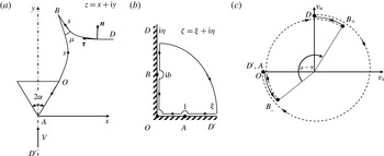
. A sketch of the problem is shown in figure 1. At the instant the apex of the body meets the liquid surface, points
 $A$
,
 $O$
and
 $B$
are the same point. Immediately after the impact, there appears a splash jet
 $OB$
with tip angle
 ${\it\mu}$
at point
 $B$
which has moved away from point
 $A$
at a constant speed, forming the cavity free surface
 $OB$
. The flow separates from the body at point
 $O$
and
 $OA$
is the body surface which is fixed in the self-similarity plane
 $z$
. The complex potential
 $W(Z,t)$
can be written in the form
 $$\begin{eqnarray}W(Z,t)=V^{2}tw(z)=V^{2}t[{\it\phi}(x,y)+\text{i}{\it\psi}(x,y)].\end{eqnarray}$$
(a) Similarity plane of the vertical water entry of an expanding wedge, (b) the parameter plane where the arrows in the closed line show the path of the integration in (2.9), which is opposite to the direction of vector
 ${\bf\tau}$
and variable
 $s$
, and (c) variation of the velocity angle,
 ${\it\Omega}=\arg (v_{s}+\text{i}v_{n})$
, to the flow boundary along the entire boundary of the liquid region. Continuous and step changes are shown by solid lines and dashed lines, respectively.

The problem is to determine the function
 $w(z)$
which conformally maps the similarity plane
 $z$
onto the complex velocity potential region
 $w$
. We choose the first quadrant of the
 ${\it\zeta}$
-plane in figure 1(b) as the parameter region to derive expressions for the complex velocity,
 $\text{d}w/\text{d}z$
, and for the derivative
 $\text{d}w/\text{d}{\it\zeta}$
, both as functions of the variable
 ${\it\zeta}$
. Then, the derivative of the mapping function is obtained as
 $\text{d}z/\text{d}{\it\zeta}=(\text{d}w/\text{d}{\it\zeta})/(\text{d}w/\text{d}z)$
, and its integration provides the mapping function
 $z=z({\it\zeta})$
.
The conformal mapping allows us to choose arbitrary locations of three points in the parameter plane. We choose point
 $O$
at the origin (
 ${\it\zeta}=0$
),
 $D$
(
 $D^{\prime }$
) at infinity and
 $A$
at
 ${\it\zeta}=1$
(see figure 1(b)). The interval
 $0<{\it\xi}<1$
of the real axis then corresponds to the body surface and
 $1<{\it\xi}<\infty$
corresponds to the symmetry line
 $AD^{\prime }$
. The interval
 $0<{\it\eta}<b$
of the imaginary axis corresponds to the cavity surface
 $OB$
and
 $b<{\it\eta}<\infty$
corresponds to the main free surface
 $BD$
. The boundary-value problem for the complex velocity function is formulated as follows:
 $$\begin{eqnarray}\displaystyle v({\it\eta})=\left|\frac{\text{d}w}{\text{d}z}\right|_{{\it\zeta}=\text{i}{\it\eta}},\quad 0<{\it\eta}<\infty , & & \displaystyle\end{eqnarray}$$
 $$\begin{eqnarray}\displaystyle {\it\chi}({\it\xi})=\arg \left(\frac{\text{d}w}{\text{d}z}\right)=\left\{\begin{array}{@{}l@{}}-{\rm\pi}/2+{\it\alpha},\quad 0<{\it\xi}<1,\\ -{\rm\pi}/2,\qquad \quad 1<{\it\xi}<\infty ,\end{array}\right. & & \displaystyle\end{eqnarray}$$
 $v({\it\eta})$
is the magnitude of the velocity on both the cavity and the main free surfaces, and
 ${\it\chi}({\it\xi})$
is the argument of the complex velocity along the wetted surface of the wedge and the symmetry line, both of which have to be determined later from the dynamic and kinematic boundary conditions. With (2.2) and (2.3), following Semenov & Iafrati (Reference Semenov and Iafrati2006), Semenov & Cummings (Reference Semenov and Cummings2006), we may write
 $$\begin{eqnarray}\frac{\text{d}w}{\text{d}z}=v_{\infty }\exp \left[\frac{1}{{\rm\pi}}\int _{0}^{\infty }\frac{\text{d}{\it\chi}}{\text{d}{\it\xi}}\ln \left(\frac{{\it\zeta}+{\it\xi}}{{\it\zeta}-{\it\xi}}\right)\text{d}{\it\xi}-\frac{\text{i}}{{\rm\pi}}\int _{0}^{\infty }\frac{\text{d}\ln v}{\text{d}{\it\eta}}\ln \left(\frac{{\it\zeta}-\text{i}{\it\eta}}{{\it\zeta}+\text{i}{\it\eta}}\right)\text{d}{\it\eta}+\text{i}{\it\chi}_{\infty }\right],\end{eqnarray}$$
where
 $v_{\infty }=v({\it\eta})_{{\it\eta}\rightarrow \infty }$
and
 ${\it\chi}_{\infty }={\it\chi}({\it\xi})_{{\it\xi}\rightarrow \infty }$
. Substituting (2.2) and (2.3) into (2.4), evaluating the first integral over the step change at
 ${\it\xi}=1$
and taking into account that
 $\arg ({\it\zeta}-\text{i}{\it\eta})=\arg (\text{i}{\it\eta}-{\it\zeta})-{\rm\pi}$
in the second integral, we obtain
 $$\begin{eqnarray}\frac{\text{d}w}{\text{d}z}=v_{0}\left(\frac{{\it\zeta}-1}{{\it\zeta}+1}\right)^{{\it\alpha}/{\rm\pi}}\exp \left[-\frac{\text{i}}{{\rm\pi}}\int _{0}^{\infty }\frac{\text{d}\ln v}{\text{d}{\it\eta}}\ln \left(\frac{\text{i}{\it\eta}-{\it\zeta}}{\text{i}{\it\eta}+{\it\zeta}}\right)\text{d}{\it\eta}-\text{i}\frac{{\rm\pi}}{2}\right],\end{eqnarray}$$
where
 $v_{0}=v({\it\eta})_{{\it\eta}=0}$
.
We introduce the unit vectors
 $\boldsymbol{n}$
and
 ${\bf\tau}$
which are normal and tangent to the boundary, respectively (see figure 1
a). With these notations we write
 $$\begin{eqnarray}\text{d}w=(v_{s}+\text{i}v_{n})\,\text{d}s=v\text{e}^{\text{i}{\it\Omega}}\,\text{d}s,\end{eqnarray}$$
where
 $s$
is the arc length of the free surface measured from point
 $B$
,
 ${\it\Omega}=\arg (v_{s}+\text{i}v_{n})$
,
 $v_{n}$
and
 $v_{s}$
are the normal and tangential velocity components, respectively. According to the definition of the vectors
 $\boldsymbol{n}$
and
 ${\bf\tau}$
in figure 1(a), the variation of function
 ${\it\Omega}({\it\zeta})$
along the entire boundary of the fluid domain is shown in figure 1(c). Along the real axis in the
 ${\it\zeta}$
-plane
 ${\it\Omega}({\it\zeta})_{{\it\zeta}={\it\xi}}={\rm\pi}$
, since
 $v_{n}=0$
and
 $v_{s}<0$
. To reduce the notation
 ${\it\Omega}({\it\zeta})_{{\it\zeta}=\text{i}{\it\eta}}$
, we introduce the function
 ${\it\theta}({\it\eta})={\it\Omega}({\it\zeta})_{{\it\zeta}=\text{i}{\it\eta}}$
, which varies continuously along
 $OB$
and
 $BD$
, or on the intervals
 $(0,b)$
and
 $(b,\infty )$
on the
 ${\it\eta}$
-axis. At point
 $B$
,
 ${\it\theta}({\it\eta})$
has a jump. When we move along an infinitesimal semi-circle centred at point
 $B$
(
 ${\it\zeta}=\text{i}b$
) in a counter-clockwise direction, this corresponds to moving along the vicinity of the tip of the jet in the similarity plane
 $z$
. Therefore, the jump in
 ${\it\theta}({\it\eta})$
equals
 $-{\rm\pi}+{\it\mu}$
, where
 ${\it\mu}$
is the angle at point
 $B$
.
Based on the above considerations, we can write the function
 ${\it\Omega}({\it\zeta})$
as follows:
 $$\begin{eqnarray}{\it\Omega}({\it\zeta})=\arg \left(\frac{\text{d}w}{\text{d}s}\right)=\left\{\begin{array}{@{}ll@{}}{\rm\pi}, & 0<{\it\xi}<\infty ,\quad {\it\eta}=0,\\ {\it\lambda}({\it\eta}), & {\it\xi}=0,\quad 0<{\it\eta}<b,\\ {\it\lambda}({\it\eta})-{\rm\pi}+{\it\mu}, & {\it\xi}=0,\quad b<{\it\eta}<\infty ,\end{array}\right.\end{eqnarray}$$
where
 ${\it\lambda}({\it\eta})$
is a continuous function. Equation (2.6) allows us to determine the argument of the derivative of the complex potential
 $$\begin{eqnarray}{\it\vartheta}({\it\zeta})=\arg \left(\frac{\text{d}w}{\text{d}{\it\zeta}}\right)=\arg \left(\frac{\text{d}w}{\text{d}s}\right)+\arg \left(\frac{\text{d}s}{\text{d}{\it\zeta}}\right)={\it\Omega}({\it\zeta})+\left\{\begin{array}{@{}ll@{}}0, & \quad 0<{\it\xi}<\infty ,\quad {\it\eta}=0,\\ {\rm\pi}/2, & \quad {\it\xi}=0,\quad 0<{\it\eta}<\infty .\end{array}\right.\end{eqnarray}$$
The function
 ${\it\lambda}({\it\eta})$
increases continuously as shown by solid lines in figure 1(c). At point
 $O$
 ${\it\lambda}(0)={\it\theta}(0)={\rm\pi}$
, and at point
 $D$
,
 ${\it\theta}_{D}={\it\lambda}({\it\eta})_{{\it\eta}=\infty }-{\rm\pi}+{\it\mu}={\rm\pi}/2$
as it can be seen in figure 1(c). Then, the angle of the splash jet tip is obtained from
 ${\it\mu}=3/2{\rm\pi}-{\it\lambda}({\it\eta})_{{\it\eta}=\infty }$
, where the function
 ${\it\lambda}({\it\eta})$
together with the function
 $v({\it\eta})$
will be determined later from dynamic and kinematic free-surface boundary conditions. Using (2.8) and the integral formula in Semenov & Cummings (Reference Semenov and Cummings2006) and Semenov & Iafrati (Reference Semenov and Iafrati2006), we have
 $$\begin{eqnarray}\frac{\text{d}w}{\text{d}{\it\zeta}}=K\exp \left[\frac{1}{{\rm\pi}}\int _{\infty }^{0}\frac{\text{d}{\it\vartheta}}{\text{d}{\it\xi}}\ln \left({\it\zeta}^{2}-{\it\xi}^{2}\right)\text{d}{\it\xi}+\frac{1}{{\rm\pi}}\int _{0}^{\infty }\frac{\text{d}{\it\vartheta}}{\text{d}{\it\eta}}\ln \left({\it\zeta}^{2}+{\it\eta}^{2}\right)\text{d}{\it\eta}+\text{i}{\it\vartheta}_{\infty }\right],\end{eqnarray}$$
where
 $K$
is a real factor and
 ${\it\vartheta}_{\infty }={\it\vartheta}({\it\zeta})_{|{\it\zeta}|\rightarrow \infty }$
. By substituting (2.8) into (2.9) and evaluating the integrals over each step change of the function
 ${\it\vartheta}({\it\zeta})$
in the direction shown in figure 1(b), we obtain
 $$\begin{eqnarray}\frac{\text{d}w}{\text{d}{\it\zeta}}=K{\it\zeta}(b^{2}+{\it\zeta}^{2})^{{\it\mu}/{\rm\pi}-1}\exp \left[\frac{1}{{\rm\pi}}\int _{0}^{\infty }\frac{\text{d}{\it\lambda}}{\text{d}{\it\eta}}\ln \left({\it\zeta}^{2}+{\it\eta}^{2}\right)\text{d}{\it\eta}-\text{i}{\rm\pi}\right].\end{eqnarray}$$
The integration of this equation allows us to obtain the function
 $w({\it\zeta})$
which conformally maps the parameter region onto the corresponding region in the complex potential plane.
 $$\begin{eqnarray}w({\it\zeta})=w_{A}+K\int _{1}^{{\it\zeta}}{\it\zeta}^{\prime }(b^{2}+{\it\zeta}^{\prime ^{2}})^{{\it\mu}/{\rm\pi}-1}\exp \left[\frac{1}{{\rm\pi}}\int _{0}^{\infty }\frac{\text{d}{\it\lambda}}{\text{d}{\it\eta}}\ln \left({\it\zeta}^{\prime ^{2}}+{\it\eta}^{2}\right)\text{d}{\it\eta}-\text{i}{\rm\pi}\right]\text{d}{\it\zeta}^{\prime },\end{eqnarray}$$
where
 $w_{A}$
is the complex potential at point
 $A$
and can be treated as an additive constant.
Dividing (2.10) by (2.5), we obtain the derivative of the mapping function
 $$\begin{eqnarray}\displaystyle \frac{\text{d}z}{\text{d}{\it\zeta}} & = & \displaystyle \frac{K{\it\zeta}}{v_{0}}\left(\frac{1+{\it\zeta}}{1-{\it\zeta}}\right)^{{\it\alpha}/{\rm\pi}}(b^{2}+{\it\zeta}^{2})^{{\it\mu}/{\rm\pi}-1}\exp \left[\frac{1}{{\rm\pi}}\int _{0}^{\infty }\frac{\text{d}{\it\lambda}}{\text{d}{\it\eta}}\ln \left({\it\eta}^{2}+{\it\zeta}^{2}\right)\text{d}{\it\eta}\right.\nonumber\\ \displaystyle & + & \displaystyle \left.\frac{\text{i}}{{\rm\pi}}\int _{0}^{\infty }\frac{\text{d}\ln v}{\text{d}{\it\eta}}\ln \left(\frac{\text{i}{\it\eta}-{\it\zeta}}{\text{i}{\it\eta}+{\it\zeta}}\right)\text{d}{\it\eta}+\text{i}\left(\frac{{\rm\pi}}{2}+{\it\alpha}\right)\right].\end{eqnarray}$$
Integration of this equation yields the mapping function
 $z=z({\it\zeta})$
relating the parameter and the similarity planes.
The unknown parameter
 $K$
is determined from the following consideration. In the physical plane, the position of point
 $B$
,
 $Z_{B}=Vtz_{B}$
, can be related to the particle velocity, which is the constant
 $Vv_{B}\text{e}^{\text{i}{\it\beta}_{B}}$
. Thus, we can write in the similarity plane
 $$\begin{eqnarray}z_{B}=v_{B}\text{e}^{\text{i}{\it\beta}_{B}},\end{eqnarray}$$
where the left-hand side
 $z_{B}=z({\it\zeta})_{{\it\zeta}=\text{i}b}$
and
 $v_{B}\text{e}^{\text{i}{\it\beta}_{B}}=\overline{\text{d}w/\text{d}z}_{{\it\zeta}=\text{i}b}$
from which the parameter
 $K$
is obtained.
The expressions in (2.5) and (2.10) contain the unknown non-singular functions
 $v({\it\eta})$
and
 ${\it\lambda}({\it\eta})$
, which have to be determined from the dynamic and kinematic boundary conditions. On the free surface
 $OBD$
of the self-similar flow these conditions can be written in the following form (Semenov & Iafrati Reference Semenov and Iafrati2006):
 $$\begin{eqnarray}\frac{\text{d}{\it\lambda}}{\text{d}{\it\eta}}=\frac{v+s\cos {\it\theta}}{s\sin {\it\theta}}\frac{\text{d}\ln v}{\text{d}{\it\eta}},\end{eqnarray}$$
 $$\begin{eqnarray}\frac{1}{\tan {\it\theta}}\frac{\text{d}\ln v}{\text{d}{\it\eta}}=\frac{\text{d}}{\text{d}{\it\eta}}\left[\arg \left(\frac{\text{d}w}{\text{d}z}\right)_{{\it\zeta}=\text{i}{\it\eta}}\right],\end{eqnarray}$$
where
 ${\it\theta}({\it\eta})={\it\Omega}({\it\zeta})_{{\it\zeta}=i{\it\eta}}$
and
 $\text{d}{\it\theta}/\text{d}{\it\eta}=\text{d}{\it\lambda}/\text{d}{\it\eta}$
from (2.7). The arc length coordinate
 $s({\it\eta})=\int _{b}^{{\it\eta}}\left(\text{d}s/\text{d}{\it\eta}^{\prime }\right)\text{d}{\it\eta}^{\prime }$
, where
 $\text{d}s/\text{d}{\it\eta}=-|\text{d}z/\text{d}{\it\zeta}|_{{\it\zeta}=i{\it\eta}}$
is obtained from (2.12).
By writing (2.5) for
 ${\it\zeta}=\text{i}{\it\eta}$
, the argument
 $\arg (\text{d}w/\text{d}z)$
can be derived, whose differentiation with respect to
 ${\it\eta}$
leads to the following integral equation for the function
 $\text{d}\ln v/\text{d}{\it\eta}$
:
 $$\begin{eqnarray}-\frac{1}{\tan {\it\theta}}\frac{\text{d}\ln v}{\text{d}{\it\eta}}+\frac{1}{{\rm\pi}}\int _{0}^{\infty }\frac{\text{d}\ln v}{\text{d}{\it\eta}^{\prime }}\frac{2{\it\eta}^{\prime }}{{\it\eta}^{\prime 2}-{\it\eta}^{2}}\text{d}{\it\eta}^{\prime }=\frac{2{\it\alpha}}{{\rm\pi}}\frac{1}{1+{\it\eta}^{2}}.\end{eqnarray}$$
The system of equations (2.14) and (2.16) enables us to determine the functions
 ${\it\theta}({\it\eta})$
and
 $\text{d}\ln v/\text{d}{\it\eta}$
. Then, the velocity magnitude on the free surface can be obtained from
 $$\begin{eqnarray}v({\it\eta})=v_{\infty }\exp \left(-\int _{{\it\eta}}^{\infty }\frac{\text{d}\ln v}{\text{d}{\it\eta}^{\prime }}\text{d}{\it\eta}^{\prime }\right).\end{eqnarray}$$
The pressure coefficient
 $c_{p}$
based on the ambient pressure,
 $P_{a}$
, and normalized by
 ${\it\rho}V^{2}/2$
, where
 ${\it\rho}$
is the liquid density, can be evaluated in the same way as for the self-similar problem of impact between two liquid wedges (Semenov et al.
Reference Semenov, Wu and Oliver2013).
 $$\begin{eqnarray}c_{p}({\it\xi})=c_{p}^{\ast }({\it\xi})-c_{p}^{\ast }({\it\xi})_{{\it\xi}=0},\end{eqnarray}$$
where
 $$\begin{eqnarray}c_{p}^{\ast }=\frac{2(P-P_{A})}{{\it\rho}V^{2}}=\text{Re}\left(-2w+2z\frac{\text{d}w}{\text{d}z}\right)-\left|\frac{\text{d}w}{\text{d}z}\right|^{2},\end{eqnarray}$$
and
 $P_{A}$
is the pressure at the stagnation point, and the functions
 $w=w({\it\zeta})$
,
 $z=z({\it\zeta})$
and
 $\text{d}w/\text{d}z$
are determined from (2.11), (2.12) and (2.5) at
 ${\it\zeta}=\text{i}{\it\eta}$
, respectively. Here,
 $\text{Re}$
indicates the real part of the expression.
We can choose
 $b$
in our solution, which then determines the wedge expansion speed. According to the definition of the self-similar variables, the
 $y$
-coordinate of point
 $D$
,
 $y_{D}=1$
, and the arc length of
 $OB$
,
 $l_{c}\sim y_{D}$
. The length
 $OA$
,
 $l_{w}=U/V$
, equals the wedge expansion speed.
We now consider some special cases in the present formulation.
For the steady Helmholtz flow,
 $U\rightarrow 0$
, or
 $l_{w}\rightarrow 0$
. Point
 $B$
approaches point
 $D$
, or
 $b\rightarrow \infty$
as can be seen from figure 1(b). Besides,
 $v({\it\eta})\equiv v_{\infty }=1$
, or
 $\text{d}\ln v/\text{d}{\it\eta}\equiv 0$
and the normal velocity on the cavity surface is zero, which means
 ${\it\lambda}({\it\eta})={\it\theta}({\it\eta})\equiv -{\rm\pi}$
,
 $0<{\it\eta}<b$
. Then, the angle at point
 $B$
becomes
 ${\it\mu}=3{\rm\pi}/2-{\it\lambda}_{\infty }={\rm\pi}/2$
. By substituting these expressions into (2.5) and (2.10) we obtain
 $$\begin{eqnarray}\frac{\text{d}w}{\text{d}{\it\zeta}}=K^{\prime }{\it\zeta},\quad \frac{\text{d}w}{\text{d}z}=-\text{i}\left(\frac{{\it\zeta}-1}{{\it\zeta}+1}\right)^{{\it\alpha}/{\rm\pi}},\end{eqnarray}$$
which is the solution for the steady Helmholtz flow past the fixed wedge (Gurevich Reference Gurevich1965). Here,
 $K^{\prime }$
is a new constant, determined from the given length of the wedge.
Flow without detachment. For the case
 $b=0$
, points
 $O$
and
 $B$
become the same point and (2.10) takes the form
 $$\begin{eqnarray}\frac{\text{d}w}{\text{d}{\it\zeta}}=K{\it\zeta}^{2{\it\mu}/{\rm\pi}-1}\exp \left[\frac{1}{{\rm\pi}}\int _{0}^{\infty }\frac{\text{d}{\it\lambda}}{\text{d}{\it\eta}}\ln \left({\it\zeta}^{2}+{\it\eta}^{2}\right)\text{d}{\it\eta}-\text{i}{\rm\pi}\right],\end{eqnarray}$$
which coincides with that obtained by Semenov & Iafrati (Reference Semenov and Iafrati2006) for an infinite wedge or the initial stage of a finite wedge. Obviously, the expansion speed
 $U$
coincides with the speed of the flow at the contact point
 $O$
in the present formulation for the expanding wedge.
Impulse solution for a flat plate of fixed finite length
 $2L$
. This solution can be obtained as the special case of an expanding plate here. At the time of impulse motion,
 $t=0$
, the free surface is flat, and points
 $O$
and
 $B$
coincide. Therefore, we can take
 $b=0$
and
 ${\it\mu}={\rm\pi}$
in the present formulation. The velocity direction,
 ${\it\beta}({\it\eta})=-\text{arg}(\text{d}w/\text{d}z)_{{\it\zeta}=i{\it\eta}}$
, generated by the impulse is perpendicular to the free surface, or
 ${\it\beta}({\it\eta})\equiv {\rm\pi}/2$
and
 ${\it\theta}({\it\eta})\equiv {\rm\pi}/2$
or
 $\text{d}{\it\lambda}/\text{d}{\it\eta}\equiv 0$
. Then, the derivative of the complex potential from Eq. (2.10) becomes
 $\text{d}w/\text{d}{\it\zeta}=K$
, or
 $w({\it\zeta})=K{\it\zeta}$
. By determining the argument of the complex velocity from Eq.(2.5) and using the condition
 ${\it\beta}({\it\eta})\equiv {\rm\pi}/2$
we obtain the following integral equation for the function
 $\text{d}\ln v/\text{d}{\it\eta}$
:
 $$\begin{eqnarray}\frac{1}{{\rm\pi}}\int _{0}^{\infty }\frac{\text{d}\ln v}{\text{d}{\it\eta}^{\prime }}\ln \left|\frac{{\it\eta}^{\prime }-{\it\eta}}{{\it\eta}^{\prime }+{\it\eta}}\right|\text{d}{\it\eta}^{\prime }+\tan ^{-1}{\it\eta}=\frac{{\rm\pi}}{2},\end{eqnarray}$$
whose solution is the function (Polyanin & Manzhirov Reference Polyan and Manzhirov2008)
 $$\begin{eqnarray}\frac{\text{d}\ln v}{\text{d}{\it\eta}}=\frac{{\it\eta}}{1+{\it\eta}^{2}}-\frac{1}{{\it\eta}},\quad v({\it\eta})=\frac{\sqrt{1+{\it\eta}^{2}}}{{\it\eta}}.\end{eqnarray}$$
As the flow direction is along the
 $y$
axis,
 $v({\it\eta})$
obtained here is also the vertical velocity on the free surface. The
 $x$
-coordinate of the free surface at a given
 ${\it\eta}$
is obtained by integration of the function
 $\text{d}x/\text{d}{\it\eta}=-\text{Re}(\text{d}z/\text{d}{\it\zeta})_{{\it\zeta}=\text{i}{\it\eta}}$
. We have
 $$\begin{eqnarray}x({\it\eta})=\sqrt{1+{\it\eta}^{2}}.\end{eqnarray}$$
By eliminating the parameter variable
 ${\it\eta}$
from
 $x=x({\it\eta})$
and
 $v=v({\it\eta})$
we obtain the well-known formula for the velocity on the free surface as a function of the coordinate
 $x$
 $$\begin{eqnarray}v(x)=\frac{x}{\sqrt{x^{2}-1}},\end{eqnarray}$$
where
 $x=1$
at the edge of the plate for an appropriate value of the factor
 $K$
.
3 Results and discussion
The general solution derived in § 2 contains the free parameter
 $b$
which determines the expansion speed of the wedge,
 $l_{w}$
. For
 $b\rightarrow \infty$
, the solution tends to the steady solution, or the expansion speed
 $l_{w}\rightarrow 0$
, while for
 $b\rightarrow 0$
, the solution tends to that without flow detachment or
 $l_{w}\rightarrow l_{wmax}$
, where
 $l_{wmax}$
is the maximal expansion speed, above which flow detachment will not happen.
 $l_{wmax}$
is finite for the case of a wedge with
 $2{\it\alpha}<{\rm\pi}$
, and it tends to infinity for the case of a plate,
 $2{\it\alpha}={\rm\pi}$
. Below we have presented some of the results in terms of the expansion speed
 $l_{w}$
.
The solution procedure is based on that in Semenov & Iafrati (Reference Semenov and Iafrati2006). The
 ${\it\xi}$
and
 ${\it\eta}$
axes are first discretized and the numerical solution is obtained through successive iteration.
3.1 Water entry of an expanding wedge
We consider a case of an expanding wedge with half-inner-angle
 ${\it\alpha}=30^{\circ }$
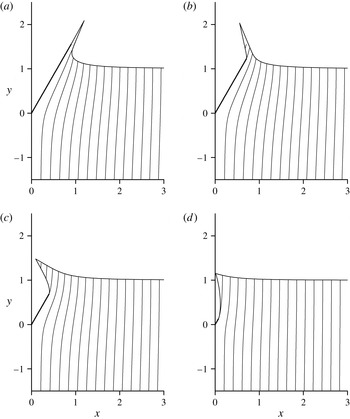
. The streamline patterns at different values of
 $b$
are shown in figure 2 for
 ${\it\alpha}=30^{\circ }$
. The wedge surface is shown as a thick line. The slopes of the streamlines show the flow velocity direction, and their density show the velocity magnitude since the flowrate between the streamlines is constant. In the figure, the flow configuration is presented in the similarity plane
 $z$
. The vertical coordinate of the free surface at
 $x\rightarrow \infty$
equals unity because the incoming flow velocity is chosen as the reference velocity. The length of the wedge side is equal to the expansion speed,
 $l_{w}$
, which depends on the parameter
 $b$
. As discussed in § 2, for the case of
 $b\rightarrow 0$
the solution tends to that corresponding to the initial stage of the water entry of a finite fixed-length wedge, for which the tip of the jet is on the body surface. In the present formulation, this is in fact equivalent to the case in which the expansion speed of the wedge,
 $l_{w}$
, is the same as the speed of the tip of the jet.
Streamline patterns with increment
 ${\rm\Delta}{\it\psi}=0.2$
in the similarity plane for an expanding wedge of half-angle
 ${\it\alpha}=30^{\circ }$
at different expansion speeds: (a)
 $l_{w}=1.795$
,
 $b=0.001$
; (b)
 $l_{w}=1.415,b=0.1$
; (c)
 $l_{w}=0.789,b=0.5$
; (d)
 $l_{w}=0.146,b=2.0$
.

As
 $b$
increases from
 $0.001$
in figure 2(a) to
 $0.1$
in figure 2(c), the jet bends inwards and the angle at the jet tip increases. At
 $b=0.5$
in figure 2(c), this trend continues. At the much larger value of
 $b=2$
shown in figure 2(d), the tip of the jet nearly touches the
 $y$
axis. For the limiting case
 $b\rightarrow \infty$
it is expected that the ratio
 $l_{w}/l_{c}\rightarrow 0$
, where
 $l_{c}$
is the length of the cavity measured from point
 $O$
to
 $B$
. This limiting case corresponds to the steady cavity flow of a fixed wedge at
 $t\rightarrow \infty$
. The half-width of the steady cavity,
 $X_{c}$
, tends to infinity at a rate of
 $X_{c}\sim \ln Y_{c}\sim \ln Vt$
(Batchelor Reference Batchelor1967). Therefore in the similarity plane
 $x_{c}=X_{c}/(Vt)\sim \ln (Vt)/(Vt)=0$
. Graphically, the cavity surface
 $OB$
in the limiting case becomes the cut
 $0\leqslant y\leqslant 1$
, while the free surface
 $BD$
becomes the line
 $0<x<\infty$
,
 $y=1$
. Therefore, the angle between the main free surface and the cavity surface
 ${\it\mu}={\rm\pi}/2$
. Such a tendency can already be seen in figure 2(d).
The results in the self-similar plane are time independent. In the physical plane, a wedge which expands from zero length with speed
 $Vl_{w}$
will reach a length
 $L$
at the time
 $$\begin{eqnarray}t=\frac{L}{Vl_{w}},\end{eqnarray}$$
which, when non-dimensionalized, will become
 $t^{\prime }=tV/L=1/l_{w}$
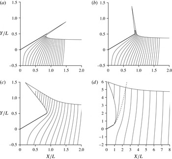
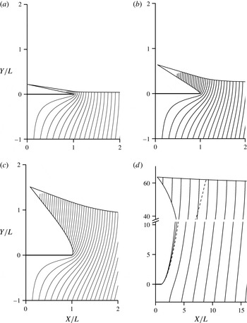
. Figure 3 provides the results for a wedge of half-angle
 ${\it\alpha}=60^{\circ }$
in the physical plane for different expansion speeds at the moment when the plate length has reached
 $L$
. For the case
 $b=0.001$
shown in figure 3(a), the expansion speed is slightly smaller than the speed of the jet tip. Because the pressures on both sides of the jet are the same, there is no lateral force which bends the jet and its main direction is along the wedge surface. This case is also related to earlier stage of impact of a finite wedge at the time when the jet tip has just left the wedge. As
 $b$
increases, the expansion speed slows. This is related to the later stage of entry of a wedge of fixed length where the jet root has passed the edge of the wedge. The jet itself begins to bend towards the
 $y$
axis. As
 $b$
further increases in figure 3(b,c), it is related to even later stage of a fixed wedge. It should be pointed out that the jet
 $OB$
leaves the wedge at
 $O$
tangentially according to (2.5) at
 ${\it\zeta}=0$
, even though the curve may appear to turn sharply at this point.
Streamline patterns in the physical plane for an expanding wedge of half-angle (
 ${\it\alpha}=60^{\circ }$
) at different speeds of expansion at time
 $t=L/(Vl_{w})$
at which the length of the wedge side becomes equal to
 $L$
(
 $t^{\prime }=1/l_{w}$
): (a)
 $t^{\prime }=0.305$
; (b)
 $t^{\prime }=0.358$
; (c)
 $t^{\prime }=0.725$
; (d)
 $t^{\prime }=4.61$
. The dashed line in (d) corresponds to the steady Helmholtz flow.

The case shown in figure 3(d) at smaller expansion speed, or a larger
 $t$
in the sense defined by (3.1). The cavity shape begins to evolve towards that corresponding to the steady Helmholtz flow. The two results are close to each other near the wedge, while they differ significantly away from the wedge. This is similar to the transient problem of a fixed-length wedge. The flow near the wedge will tend to the steady one earlier, and the flow far behind the wedge will take longer time to become steady. Here it can be expected when
 $l_{w}\rightarrow 0$
or
 $t\rightarrow \infty$
in (3.1), the corner point
 $B$
will move to infinity and the free surface will approach that in the Helmholtz steady cavity flow.
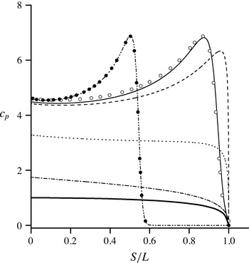
Pressure coefficient on the wedge surface for the cases in figure 3: solid line (a), dashed line (b), dotted line (c) and dash-dotted line (d); dot-dot-dashed line for time
 $t^{\prime }=0.177$
; closed circles are the results of Zhao & Faltinsen (Reference Zhao and Faltinsen1993) for the water entry of an infinite wedge, open circles are the same as the closed circles but with
 $S/L$
calculated at
 $t^{\prime }=0.295$
; the thick solid line corresponds to the steady Helmholtz flow.

The pressure coefficient on the wedge surface is shown in figure 4 for different expansion speeds, or different
 $t$
based on (3.1).
 $S=Vts$
in the figure is the distance to the tip of the wedge in the physical plane. When
 $t$
is taken from (3.1),
 $S=sL/l_{w}=sLt^{\prime }$
. For the case
 $b=0$
, or
 $l_{w}=l_{wmax}=5.65$
, (dot-dot-dashed line) the result coincides with that of Zhao & Faltinsen (Reference Zhao and Faltinsen1993) (closed circles) for an infinite wedge. The self-similar result for an infinite wedge is also shown as opened circles at
 $t^{\prime }=0.295$
through rescaling
 $S=sLt^{\prime }$
, in which
 $s$
remains the same as that at
 $t^{\prime }=0.177$
while
 $t^{\prime }$
itself is adjusted. As long as the jet root in the case of an expanding wedge still remains on the body surface (see figure 3
a), the pressure is quite close to that for an infinite wedge. For the case shown in figure 3(b), the jet root has left the wedge but is still near the edge of the wedge, and therefore the pressure decreases only slightly. As the jet root further moves away from the wedge (at smaller
 $l_{w}$
), the pressure on the wedge further decreases, and it will gradually tend to that of the steady Helmholtz flow when
 $t^{\prime }\rightarrow \infty$
.
We may link further the present similarity solution of an expanding wedge with that of a finite wedge of fixed length
 $L$
to investigate the similarity and the difference between the two cases. At the initial stage before the jet tip leaves the fixed-length wedge, the solution will be self-similar and it corresponds to that of an expanding wedge with
 $l_{w}=l_{wmax}$
. When the jet tip leaves the fixed-length wedge, the solution will become fully transient, or time dependent. Corresponding to each time in figure 3, the tips of the fixed-length and the expanding wedges are at the same location, and their lengths are the same. However, their flow features are not identical, as the former is time dependent and the latter is self similar. On the other hand, as
 $t^{\prime }\rightarrow \infty$
, the flows in both cases approach the steady Helmholtz one. Therefore, the flows in these two cases are initially the same at
 $l_{w}=l_{wmax}$
. They become non-identical when
 $0<l_{w}<l_{wmax}$
, and then they tend to identical again when
 $t^{\prime }\rightarrow \infty$
, or
 $l_{w}\rightarrow 0$
.
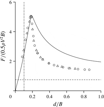
The problem of a finite wedge entering the water has been studied previously. In particular, by Zhao et al. (Reference Zhao, Faltinsen and Aarsnes1997), Iafrati & Battistin (Reference Iafrati and Battistin2003), Maki et al. (Reference Maki, Lee, Troesch and Vlahopoulos2011) using the fully nonlinear time stepping method. The results of Iafrati & Battistin (Reference Iafrati and Battistin2003), Maki et al. (Reference Maki, Lee, Troesch and Vlahopoulos2011) for the vertical force
 $F$
acting on the wedge are shown in figure 5, in which
 $B=2L\sin {\it\alpha}$
is the width of the wedge top and
 $d=Vt$
is the depth of the vertex. We have also given the results based on the present self-similar solution for the expanding wedge in the figure. As discussed above, the positions and lengths of the expanding and fixed wedges are the same. For forces at early stage before flow separation are in full agreement as the flow configuration for the fixed wedge is also self-similar. After the jet tip leaves the wedge, the transition stage of the fixed wedge starts. However, as the jet root is on the wedge surface, the force is still close to the self-similar solution. The difference starts when the jet root leaves the wedge. As the peak pressure at the jet root no longer exists, the forces in both cases decrease very quickly. As
 $t$
increases, the force in both cases will tend to that corresponding to the steady Helmholtz flow.
At the transition stage, the hydrodynamic force for the expanding wedge is larger than that on the fixed wedge. It is the expected result, because the hydrodynamic force for the expanding wedge includes a contribution caused by the wedge expansion, which can be seen from the temporal derivative of the equivalent plate width in the equation for pressure (Faltinsen Reference Faltinsen2005) based on the Wagner theory.
Vertical force history on a finite wedge at different stages of water entry: Iafrati & Battistin (Reference Iafrati and Battistin2003) (circles) and Maki et al. (Reference Maki, Lee, Troesch and Vlahopoulos2011) (triangles); the expanding wedge model (solid line). The dot-dashed line shows the beginning of the transition stage when the jet tip leaves the finite wedge. The dashed line corresponds to the steady flow.

Streamline patterns for the impact of a horizontal expanding flat plate at different values of b: (a)
 $l_{w}=24.4,t^{\prime }=0.041$
; (b)
 $l_{w}=4.11,t^{\prime }=0.243$
; (c)
 $l_{w}=1.204,t^{\prime }=0.831$
; (d)
 $l_{w}=0.0172,t^{\prime }=58.3$
.

3.2 Water entry of a plate expanding relative to its centre
The case of wedge angle
 ${\it\alpha}=90^{\circ }$
corresponds to an expanding flat plate entering a water surface. The streamline patterns in the physical plane for times
 $t^{\prime }=1/l_{w}$
, at which
 $Vl_{w}=L$
, are shown in figure 6 for different
 $l_{w}$
. Figure 6(a) for
 $l_{w}=24.4$
shows that the free surface has turned almost
 $180^{\circ }$
at the plate edge. At time
 $t=0$
, point
 $B$
of the jet tip and point
 $O$
of the plate wedge coincide with the origin at point
 $A$
in the physical plane. Then point
 $B$
will move up with a vertical velocity. Point
 $O$
will move along the
 $x$
axis with speed
 $l_{w}$
and it leaves point
 $B$
behind, as the latter has a smaller horizontal velocity. When
 $l_{w}\gg v_{B}$
, the jet will then bend
 $180^{\circ }$
as the coordinates of point
 $B$
in the similarity plane equal its velocity components (see (2.13)). When the expansion speed
 $l_{w}$
decreases, the flow turns less sharply. At
 $l_{w}=1/t^{\prime }=1.2$
in figure 6(c), the turn of the free surface at point
 $O$
is quite mild. For case (
 $d$
), the expansion speed of the plate
 $l_{w}=0.0172$
is still larger than the horizontal component of the velocity at point
 $B$
. However, it is much smaller than its vertical component. We may notice that in figure 6(d) the flow pattern near the body tends to that in the steady cavity flow past the plate, while it is still different from that away from the body. It is expected that as
 $t^{\prime }$
increases, more and more flow regions will tend to the steady solution. In other words, the flow near the plate will become steady first, while the flow away from the body will take a longer time to settle.
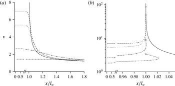
In figure 7 are shown the velocity magnitude along the main free surface
 $BD$
figure 7(a) and the cavity surface
 $OB$
figure 7(b) against
 $x/l_{w}$
for different expansion speeds. It can be seen that as
 $l_{w}$
becomes larger and larger, the velocity magnitude on the free surface
 $BD$
figure 7(a) for
 $x/l_{w}>1$
tends to that corresponding to the impulse solution shown by the solid line, while the free-surface elevation for
 $x/l_{w}>1$
tends to zero (see figure 6
a). We also notice that the vertical velocity on the plate (
 $x/l_{w}<1$
) and the horizontal velocity on the symmetry line (
 $x=0$
) are given through the boundary condition, and they are identical to those in the impulse problem. Thus, it can be expected that as
 $l_{w}\rightarrow \infty$
, the velocity corresponding to
 $y\leqslant 0$
obtained from the similarity solution of the expanding plate will tend to that from the impulse solution of a fixed-length plate. For the expanding plate there is a thin jet within
 $x/l_{w}<1$
as
 $l_{w}\rightarrow \infty$
, which is obviously missing in the impulse solution. From figure 7, it can be seen that the velocity is nearly constant at the most part of both the upper and the lower sides of the splash jet. In particular, as
 $l_{w}\rightarrow \infty$
, the thickness of the jet tends to zero, and there is no velocity jump across the jet. It is then immediate from the Cauchy integral of the complex velocity along the fluid boundary that the presence of the jet does not affect the flow in the main fluid domain,
 $y\leqslant 0$
.
Velocity magnitude along (a) the free surface
 $BD$
and (b) the cavity surface
 $OB$
. Solid line: the impulse solution; dashed line:
 $l_{w}=42.6$
; dotted line:
 $l_{w}=24.2$
; dash-dotted line:
 $l_{w}=4.11$
, dash-dot-dot line:
 $l_{w}=0.357$
. Open circles show the values at the trailing edge of the plate,
 $x/l_{w}=1$
.

The above behaviour at
 $l_{w}\rightarrow \infty$
can be explained through the evolution of the boundary condition of the problem in this limit. We may replace the length scale
 $Vt$
in (2.1) with
 $l_{w}Vt$
, or
 $W(z,t)=V^{2}l_{w}tw^{\prime }(z^{\prime })$
,
 $z^{\prime }=Z/(l_{w}Vt)$
,
 $Z(S,t)=l_{w}Vtz^{\prime }(s^{\prime })$
, similar to that in the 3-D impact of a water cone (Sun & Wu Reference Sun and Wu2014). The plate is then within
 $0\leqslant x^{\prime }\leqslant 1$
. The dynamic condition on the free surface for this self-similar problem may be written in terms of the real potential
 ${\it\phi}^{\prime }=\text{Re}(w^{\prime })$
with
 $s^{\prime }=s/l_{w}$
measured from
 $B$
(Semenov & Iafrati Reference Semenov and Iafrati2006):
 $$\begin{eqnarray}{\it\phi}^{\prime }-\frac{\text{d}{\it\phi}^{\prime }}{\text{d}s^{\prime }}s^{\prime }=\frac{v^{2}-v_{B}^{2}}{2l_{w}},\end{eqnarray}$$
where
 $s^{\prime }=0$
and
 ${\it\phi}^{\prime }=0$
correspond to the tip of the splash jet (point
 $B$
). The kinematic condition can be written in the form
 $$\begin{eqnarray}\frac{\text{d}Z}{\text{d}t}=l_{w}V\left(z^{\prime }-\frac{\text{d}z^{\prime }}{\text{d}s^{\prime }}s^{\prime }\right)=Vv\text{e}^{\text{i}{\it\beta}},\Longrightarrow z^{\prime }-\text{e}^{\text{i}{\it\gamma}}s^{\prime }=\frac{1}{l_{w}}v\text{e}^{\text{i}{\it\beta}},\end{eqnarray}$$
where
 ${\it\gamma}=\arg (\text{d}z^{\prime }/\text{d}s^{\prime })$
and
 ${\it\beta}$
is the velocity direction. As
 $l_{w}\rightarrow \infty$
, the right-hand sides of these two equations tend to zero, which leads to
 $y^{\prime }=\text{Im}z^{\prime }\rightarrow 0$
and
 ${\it\phi}^{\prime }\rightarrow 0$
on the free surface when
 $x^{\prime }>1$
. This is the same as the condition of the impulse potential and the velocity at large
 $l_{w}$
being close to the impulse solution. Care is, however, needed at
 $x^{\prime }=1$
. As
 $v(x^{\prime })=x^{\prime }/\sqrt{(x^{\prime 2}-1)}$
on the free surface based in the impulse solution, a singularity exists at
 $x^{\prime }=1$
. The right-hand sides of (3.2), (3.3) may not necessarily tend to zero as
 $l_{w}\rightarrow \infty$
at
 $x^{\prime }=1$
. The limit of
 $l_{w}\rightarrow \infty$
at that point may have its own behaviour. In fact, as can be seen in figure 6(a), the jet length
 $OB$
, initiated from
 $x^{\prime }=1$
, becomes
 $|OB|\sim 1$
, which is absent in the impulse solution. However, as we have discussed above, the thickness of the jet tends to zero, and it has no real impact on the main flow below
 $y^{\prime }=0$
. This is the reason for the behaviour of the results in figures 6 and 7 for larger expansion speeds
 $l_{w}$
.
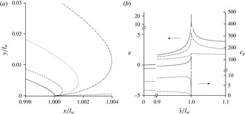
(a) Free surface near the plate edge, or the lower surface of the jet, for various expansion speeds: solid line
 $l_{w}=10.9$
; dashed line
 $l_{w}=4.11$
; dotted line
 $l_{w}=2.95$
; dash-dotted line
 $l_{w}=2.24$
; dot-dot-dashed line
 $l_{w}=0.36$
; (b) velocity magnitude and the pressure coefficient along the plate (
 $0\leqslant \bar{s}/l_{w}\leqslant 1$
) and along the free surface
 $OB$
(
 $\bar{s}/l_{w}>1$
):
 $l_{w}=10.9$
(solid line),
 $l_{w}=2.24$
(dot-dashed line) and
 $l_{w}=0.357$
(dot-dot-dashed).

In figure 8(a) are shown the local close-ups of the free surface near the edge of the plate at different
 $l_{w}$
. Here,
 $\bar{s}/l_{w}=(s_{O}-s)/l_{w}$
, where
 $s_{O}$
is the arc length coordinate at the edge of the plate. Then,
 $\bar{s}/l_{w}=0$
at the wedge apex
 $A$
and
 $\bar{s}/l_{w}>1$
along the free surface
 $OB$
. The free surface leaves the plate tangentially as it follows from (2.5) for
 ${\it\zeta}=i{\it\eta}\rightarrow 0$
. The larger the expansion speed results in larger curvature of the free surface. In figure 8(b) are shown the velocity magnitude and the pressure coefficient along the plate and the free surface
 $OB$
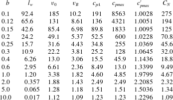
. The velocity and the pressure coefficient take their maxima values towards the edge of the plate. In the vicinity of the edge it increases with the expansion speed, and rapidly decreases in both directions away from the edge, along the plate and along the free surface.
Main reference parameters for an expanding flat plate at different
 $b$
.

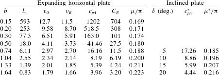
Table 1 gives the obtained expansion speed of the plate,
 $l_{w}$
, fluid velocity at the plate edge,
 $v_{0}$
, (point
 $O$
) and at the tip of the splash jet,
 $v_{B}$
, (point
 $B$
), the pressure at the stagnation point
 $A$
,
 $c_{pA}$
, and the maximum pressure on the plate,
 $c_{pmax}$
and the vertical force coefficient,
 $C_{N}=F/(0.5{\it\rho}V^{2}L)$
. For
 $b>1$
, the maximum pressure occurs at the stagnation point
 $A$
, and therefore the values of
 $c_{pA}$
and
 $c_{pmax}$
coincide. The pressure
 $c_{pmax}^{\prime }$
is the pressure coefficient normalized by the square of the non-dimensional speed of the plate edge relative to the incoming liquid,
 $c_{pmax}^{\prime }=c_{pmax}/(1+l_{w}^{2})$
. It is seen that
 $c_{pmax}^{\prime }\rightarrow 1$
at a large expansion speed. This is similar to that in water entry of a body with small deadrise angle (Howison et al.
Reference Howison, Ockendon and Wilson1991).
3.3 Comparison between flows due water entries of a slightly inclined flat plate and an expanding horizontal plate
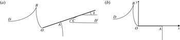
An inclined plate entering the liquid generates a splash jet near the edge, and a jet along the plate. In the latter the tip of the jet is the intersection point of the free surface and the plate, shown as
 $C$
in figure 9(a). The problem has been considered earlier by Faltinsen & Semenov (Reference Faltinsen and Semenov2008). At very small deadrise angles
 ${\it\delta}$
, for example
 ${\it\delta}<5^{\circ }$
, the contact angle at point
 $C$
becomes too small, which caused numerical difficulties in computations. We note that as the deadrise angle
 ${\it\delta}\rightarrow 0$
, the inclined plate approaches the horizontal plate. This gives a possibility of using a horizontal plate expanding relative to one of its edges to model the flow generated by an inclined plate. The zero streamline in figure 9(a) starting from the stagnation point
 $A$
has been found to be nearly a vertical straight line at small
 ${\it\delta}$
(Faltinsen & Semenov Reference Faltinsen and Semenov2008). For the flow generated by a horizontal plate expanding relative to the edge, the flows near its two edges may not be identical or the flows may not be exactly symmetric, as one edge is fixed and the other is moving. In such a case the streamline passing its stagnation point
 $A$
may not be strictly a straight line. However, when the expansion speed is sufficiently large and stagnation point
 $A$
becomes sufficiently away from the plate edge
 $O$
, the approximation made for the streamline passing
 $A$
is not expected to have significant effect on the flow near the edge. Thus we use a straight line perpendicular to the plate to approximate the streamline passing
 $A$
. As a result, the flow region
 $AOBD$
in figure 9(a) becomes consistent with that of the horizontal plate whose sketch is shown in figure 9(b) in which the edge of the plate is fixed while its centre point
 $A$
moves away from
 $O$
. In such a way, we link the problem of a slightly inclined half-infinite plate with the problem of the horizontal plate expanding relative to its fixed edge when they enter into the water surface. In both cases the distances between points
 $O$
and
 $A$
in the similarity plane are the same.
Sketch of the water-entry problem (
 $a$
) an inclined half-infinite plate and (
 $b$
) a horizontal plate expanding relative to its edge at point
 $O$
.

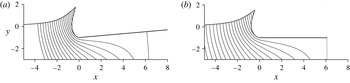
Streamlines and the free-surface shapes near the edge: (
 $a$
) the inclined plate with a deadrise angle of
 $5^{\circ }$
(based on solution by Faltinsen & Semenov (Reference Faltinsen and Semenov2008)); (
 $b$
) the expanding plate with
 $l_{w}=6.1$
.

We now put the origin of the coordinate system at point
 $O$
, where the complex potential is taken to be zero,
 $W(Z_{O},t)=0$
, or
 $w({\it\zeta})_{{\it\zeta}=0}=0$
. There is a significant difference between the two cases of the plate expansion, relative to its fixed centre and relative to its edge. In particular, it it significantly changes the orientation of the splash jet. This occurs due to (2.13) relating the velocity at point
 $B$
to its position relative to the origin of the similarity plane, and the origin is chosen at the fixed point of the plate. Indeed, for the case of the plate expansion relative to point
 $A$
, (2.13) relates points
 $A$
and
 $B$
,
 $z_{B}-z_{A}=v_{B}\text{e}^{\text{i}{\it\beta}_{B}}$
, while for the plate expanding relative to its edge at point
 $O$
(2.13) relates points
 $O$
and
 $B$
,
 $z_{B}-z_{O}=v_{B}\text{e}^{\text{i}{\it\beta}_{B}}$
. Because the velocity at point
 $B$
,
 $v_{B}\text{e}^{\text{i}{\it\beta}_{B}}$
, is affected slightly by the choice of the origin based on the fix point of the plate, the vectors
 $z_{A}z_{B}$
and
 $z_{O}z_{B}$
are close to each other. That significantly influences the orientation of the splash jet.
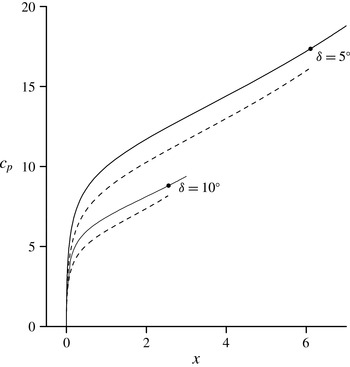
Pressure distribution along the plates: inclined (solid lines) based on solution by Faltinsen & Semenov (Reference Faltinsen and Semenov2008), horizontal and expanding (dashed lines) for
 ${\it\delta}=5^{\circ }$
,
 $l_{w}=|OA|=6.1$
, and
 ${\it\delta}=10^{\circ }$
,
 $l_{w}=|OA|=2.55$
. The solid circle corresponds to the stagnation point.

Results for a plate expanding relative to its edge and their comparison with those for an inclined plate.
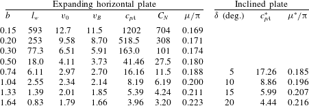
Figure 10(a) shows the streamline patterns for an inclined plate with a deadrise angle of
 ${\it\delta}=5^{\circ }$
. This is a case considered by Faltinsen & Semenov (Reference Faltinsen and Semenov2008). However we have rerun the calculations with more discrete points to ensure convergence and the figure is replotted using the updated results. We then use
 $|OA|=6.1$
in figure 10(a) for
 $l_{w}$
of the expanding horizontal plate and the streamlines for this case are given in figure 10(b). It can be seen that the flow configurations near the edge of the plate in these two cases are very close to each other. Detailed results are given in table 2, in which the relative error in the tip angle of the jet is approximately
 $1.6\,\%$
. Results for
 ${\it\delta}=10^{\circ }$
,
 $15^{\circ }$
and
 $20^{\circ }$
are also provided in the table, in which the corresponding
 $l_{w}=|OA|$
is obtained from the solution of the inclined plate for each case. It can be seen that the approximation by the expanding plate for an inclined plate is still quite good in these three angles. The accuracy of the approximation, however, does decrease slightly within this range of
 ${\it\delta}$
, as
 ${\it\delta}$
increases. Obviously, it is partly due to the fact that the inclined plate has further departed from the
 $x$
-axis, and the streamline passing point
 $A$
, will be more distorted from a straight line. The approximation of straight line used in figure 10(b) will be less accurate.
Although the approximation of the case in figure 9(a) through that in figure 9(b) is primarily for the flow near the edge of the plate, it would be interesting to see the comparison of the pressure distributions along
 $OA$
. It can be seen in figure 11 that the results for pressure distribution are in fairly good agreement.
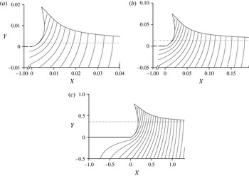
Figure 12 shows the free-surface shape and the streamline patterns for different expansion speeds. The undisturbed free surface is shown as a dotted line. As can be seen from figure 12(a), the splash jet moving away from the plate edge has a larger vertical and a smaller horizontal velocity component. A non-zero horizontal velocity component at the splash tip is a specific feature in this approximation. Based on the full solution for an inclined plate (Faltinsen & Semenov Reference Faltinsen and Semenov2008), the jet tip moves strictly in the vertical direction, and can be seen in figure 10(a), through
 $x_{B}\approx 0$
.
Streamline patterns for a plate expanding relative to its edge for different expansion speeds
 $l_{w}$
: (
 $a$
)
 $l_{w}=593$
; (
 $b$
)
 $l_{w}=77.3$
; (
 $c$
)
 $l_{w}=2.81$
.

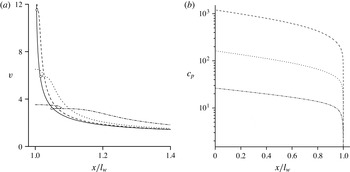
(a) Velocity along the free surface and (
 $b$
) pressure coefficient on the plate:
 $l_{w}=593.6$
(dashed line);
 $l_{w}=77.3$
(dotted line);
 $l_{w}=10.9$
(dash-dotted line); open circles correspond to point
 $B$
; the impulse solution (solid line).

The model in figure 9(b) can also be used for a horizontal plate expanding relative to its edge at large speed. In such a case, the assumption about symmetry with respect to the vertical line passing point
 $A$
, would be a good approximation as
 $A$
is far away from
 $O$
. Figure 13 shows the speed of the liquid on the free surface and the pressure distribution on the plate for different expansion speeds. The larger the expansion speed, the closer the speed distributions on the free surface are to that corresponding to the impulse solution. The behaviour of the speed on the free surface is similar to that for the plate expanding relative to its centre shown in figure 7. However, the pressure distribution on the plate shown in figure 13(b) is significantly different from that in figure 8(b). In figure 13(b) the pressure takes its maximum value at the stagnation point and gradually decreases to zero, without a pressure peak near the end of the plate, which can be seen in figure 8(b).
The main flow parameters are presented in table 2. All of them (excluding the angle of the splash jet
 ${\it\mu}$
) increase as the parameter
 $b$
decreases just as they do in the case of a plate expanding from its centre (see table 1). However, the difference between the velocities at points
 $O$
and
 $B$
is not so high as that in table 1. This is due to a smaller bending of the splash jet. The slope of the cavity surface near the plate end is turned approximately
 $90^{\circ }$
instead of
 $180^{\circ }$
for the cases presented in table 1.
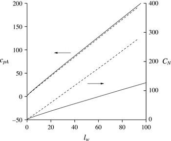
Comparison between the plate expending from its centre (dashed lines) and from the edge (solid lines): the left axis corresponds to the pressure at the stagnation point,
 $c_{pA}$
, and the right axis corresponds to the force coefficient
 $C_{N}$
.

Figure 14 shows a comparison of the pressure coefficients at the stagnation point against the expansion speed for the two different ways of plate expansion. The horizontal axis of the solid starts from
 $l_{w}=1$
, although the assumption made in 9(b) is for large
 $l_{w}$
. As can been seen, they are about the same for both cases. However, the force coefficient for the plate expanding relative to its edge is more than twice smaller than that for the plate expanding relative to its centre. It should be noticed that for the inclined plate only the part of the flow region between the stagnation point and the plate edge is considered, and the other part between the stagnation point and the contact point
 $C$
in figure 9(a) is not symmetric to it. Therefore, we do not expect the same values of the force coefficients for these two cases.
4 Conclusions
Analytical self-similar solutions for water entry of an expanding wedge and plate with flow detachment have been presented. The integral hodograph method has been employed to derive the governing functions, which are based on the complex velocity and the derivative of the complex potential defined in the parameter plane. Through the method, the problem is reduced to a system of integral and integro-differential equations after the dynamic and kinematic boundary conditions on the free surface are imposed. The formulation includes a free parameter
 $b$
whose choice determines the expansion speed,
 $l_{w}$
and covers two limiting cases. For
 $b=0$
the initial stage of water entry of a fixed length wedge without flow detachment or an infinite wedge is obtained, for which
 $l_{w}=l_{wmax}$
is the speed of the jet tip. For
 $b\rightarrow \infty$
, the expansion speed
 $l_{w}\rightarrow 0$
, thus the steady free-streamline Helmholtz flow past a finite wedge is obtained.
For
 $0<l_{w}<l_{wmax}$
the solution describes the water entry of an expanding wedge with flow detachment from the top of the wedge. At large values of
 $l_{w}$
the main free surface is close to the wedge, while for
 $l_{w}\rightarrow 0$
it moves away to infinity. The results for an expanding wedge have been compared with nonlinear numerical solutions for a wedge of fixed length penetrating a liquid. The expansion speed has been linked with the time or the penetration depth, with which the expanding wedge and the fixed-length wedge take the same values. Although the self-similar and the transient flows are different by their nature and generate different free-surface geometries, their comparison revealed a good correlation between the forces and between the flow configurations, especially at the beginning of the transition stage. For larger times/depths, the expanding wedge demonstrates a larger hydrodynamic force, which is due to the additional slamming force component caused by the variation of the wedge length.
The obtained general solution has enabled us to consider the water-entry problem of an expanding horizontal plate as a special case of a wedge of inner angle
 ${\rm\pi}$
. Two self-similar solutions of the expanding plate are presented. The first one corresponds to a plate with its centre fixed while the plate edges move away at speed
 $l_{w}$
. For
 $l_{w}\rightarrow \infty$
, the computations has revealed that the speed of the liquid on the free surface and its elevation approach those corresponding to the impulse solution of a flat plate impacting the free surface at time
 $t=0^{+}$
. The pressure distribution on the plate at large expansion speeds
 $l_{w}$
exhibits a peak near its edge. The pressure peak is associated with the plate expansion speed, similarly to the water entry of a body with a small deadrise angle (Howison et al.
Reference Howison, Ockendon and Wilson1991). The peak pressure normalized by the total speed relative to the edge
 $c_{pmax}/(1+l_{w}^{2})\rightarrow 1$
approaches unity as
 $l_{w}\rightarrow \infty$
.
The second case is a plate with a fixed edge while the other edge, and therefore the stagnation point moves away. At large expansion speed in particular, the problem can be approximated by the flow which is assumed to be symmetric about a vertical line passing the stagnation point of the plate. This has also been found to be a good approximation for the self-similar flow generated by an inclined semi-infinite flat plate entering the liquid at small angles. For expansion speed
 $l_{w}\rightarrow \infty$
the solution from this model also approaches the impulse solution. However, the splash jet orientation and pressure distribution on the plate are significantly different from those in the first case. The maximum pressure on the plate occurs at the stagnation point.
Acknowledgements
This work is supported by Lloyd’s Register Foundation (LRF) through the joint centre involving University College London, Shanghai Jiaotong University and Harbin Engineering University, to which the authors are most grateful. LRF supports the advancement of engineering-related education, and funds research and development that enhances safety of life at sea, on land and in the air.