Introduction
In the present years, Fifth Generation (5G) communication systems are more popular as they improve throughput capability and reduce overall latency of antenna which enhances transmission and reception capability of antenna. Generally, the Multiple Input and Multiple Output (MIMO) structures are more suitable for enhancing data rate capability and to achieve good level of polarization diversity performance which is required for mobile handsets. The most important issue was with the antennas orientation is ultimately resolved by circularly polarized MIMO antenna [Reference Volakis1]. The MIMO antennas are essentially used to get different directions of polarizations which enhance the entire coverage area of antenna. This type of orthogonal arrangement in feeding structure gives different circular polarization (CP) senses which ultimately improve the transmission and reception capability also essential for achieving good level of polarization diversity function. The circularly polarized antennas are not easily susceptible to multipath interferences; it reduces fading issues and also these CP antennas are free from polarization loss problems which makes it very much suitable for 5G mobile handsets [Reference Gao, Luo and Zhu2, Reference Gunjal and Kshirsagar6]. Because of its benefits over linearly polarized antennas, the multiport CP antennas were now prominently implemented in recent mobile systems [Reference Midya, Bhattacharjee and Mitra3, Reference Gunjal and Kshirsagar6]. The multiport structures are now paying more attention because these structures offer the left-handed and right-handed CP (RHCP/LHCP) characteristics [Reference Row and Shih4]. It is also possible to change the polarization statistics by simply exciting another port. The dual feed MIMO structures are more compact and light in weight in comparison with the other multiport structures and it becomes a strong candidate toward future 5G wireless/mobile systems for actual implementation purposes. Various geometries of slot antennas are available in the present literature to obtain broadband CP such as crescent-shaped slot antennas [Reference Parchin, Basherlou and Abd-Alhameed5], microstrip line slot [Reference Gunjal and Kshirsagar6, Reference Chen, Chen, Lee and Hsu7], substrate integrated waveguide slot [Reference Li, Chen, Qing, Zhang, Xu and Feng8], monopole slot [Reference Kumar and Harish9], spiral-shaped slot [Reference Siahcheshm, Nourinia, Ghobadi, Karamirad and Mohammadi10], and corner truncated slot [Reference Wu, Wei, Li and Yang11]. The antenna consists of non-uniform width elliptical slot at the bottom ground side and unequal length feed-line structure at the top side of substrate to obtain CP. Due to the use of common ground structure it is possible to suppress the mutual coupling effect amongst the antenna elements and integration with the mobile devices also becomes easier. Every antenna is surrounded by two different polarizations in MIMO environment which improves the transmission and reception capability of antenna and makes it suitable for future mobile systems [Reference Chakraborty, Rahman, Hossain, Mobashsher, Nishiyama and Toyoda12]. Meta-material-based triple band high gain vivaldi antenna is proposed for 5G mobile handsets. Four vertically polarized vivaldi antennas and four horizontally polarized spiral antennas form 8 × 8 MIMO array structure. The smaller meta-material units were protruded in the design structure to enhance the peak gain and antenna efficiency by suppressing mutual coupling behavior amongst the antennas [Reference Saeidi, Ismail, Noghanian, Alhawari, Abbasi, Imran, Zeain and Ali13]. A horseshoe-shaped ground slot and two asymmetrically fed L-shaped patches were used to obtain broadband CP. By adjusting the shape of the patches, 3 dB axial ratio bandwidth (ARBW) and − 10 dB impedance bandwidth (IBW) are improved [Reference Xu, Li, Liu, Zhou, Xing and Wei14]. The antenna consists of four vertically polarized and four horizontally polarized semi-arc-shaped radiating antenna elements. The open-ended ground slot radiator with vertically and horizontally protruded smaller square strips is used to improve the IBW and isolation amongst the antenna elements [Reference Ojaroudi Parchin, Jahanbakhsh Basherlou, Al-Yasir, Abdulkhaleq and Abd-Alhameed15]. The composite feed aperture-coupled antenna with improved characteristics is presented. The antenna has more than 18 dB isolation level and is demonstrated without using power divider [Reference Chakrabarti16]. In this article, a compact size 2 × 2 MIMO array antenna for mid-band 5G wireless applications or polarization diversity application is presented. Ground V-shaped slot and top patches were responsible for generation of LHCP and RHCP. The ground V-shaped slot is used to obtain broadband CP antenna. By adjusting the length and width of the middle square strip (K1 × K2) it is possible to enlarge IBW and also the 3 dB ARBW. The proposed dual feed antenna is also known as a 2 × 2 MIMO array antenna.
This paper is organized as follows; Introduction of proposed two-port MIMO array antenna in the first section. A detailed overview of proposed antenna geometry and its analysis in the second section. Surface current distribution analysis of CP antenna in the third section. Parametric analysis of proposed antenna in the fourth section. MIMO performance parameter analysis included in the fifth section. Simulated and measured results comparison in the sixth section, and lastly, the paper is concluded in the seventh section.
Proposed design with analysis
The top view of proposed MIMO antenna is depicted in Fig. 1. The proposed antenna structure is fabricated with the help of a square FR4 substrate material having a relative permittivity of 4.4 and a loss tangent of 0.027. Overall MIMO antenna size is 48 × 48 × 1.0 mm here. These two diamond-shaped patches on the top side of substrate are placed in such a way that both the ports have 180° of phase angle between them. The antenna has a common V-shaped slot at the bottom plane. By protruding polyline and square strips on the outer and inner counter surface of the ground V slot, improvement in IBW and gain is possible. The antenna is designed using HFSS (High Frequency Structure Simulator) 19.0 simulation software tool. The half wavelength ground slot structure is accountable for lower band CP performance and quarter wavelength structure formed by the patch feed network is accountable for upper band CP performance. By adding these two CP resonances generated by the ground V slot and top patch feed network, it is easy to obtain broadband circular radiation. The antenna shows a good simulated design symmetry when one sees it from the middle toward left-hand side part and right-hand side part of the antenna as shown in Fig. 1.
Top side view of 2 × 2 MIMO array antenna.

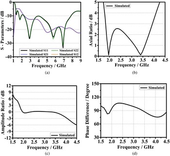
The optimized parameter values were given in Table 1. Figure 2 depicts the simulated results of the proposed MIMO antenna. The –10 dB IBW is shown in Fig. 2(a) which ranges from 1.7 to 7.8 GHz (6.1 GHz). The polygon and square strips on the outer and inner counter surface of the ground V slot enhance the IBW of antenna. The simulated S21 and S12 values are almost equal. Since patches are connected to feed directly, the electrical length of the feed line is reduced. The shorter length of feed-line has an adverse effect on isolation value at the lower frequency side. Because of this, isolation values were found to be lesser at lower frequency side in comparison with higher frequency side isolation values within the impedance bandwidth of antenna as shown in Fig. 2(a). The peak isolation of − 23 dB at 5.0 GHz frequency is obtained. Simulated 3 dB ARBW is depicted in Fig. 2(b). The 3 dB ARBW ranges from 1.82 to 3.92 GHz (2.1 GHz). The ARBW shows the peak resonances at 1.9 and 3.4 GHz respectively. The axial ratio graph is in close proximity to 0 dB at these frequencies. Simulated amplitude ratio shown in Fig. 2(c) is exactly equal to 0 dB at 1.9 and 3.4 GHz frequency. Similarly, the simulated phase difference is shown in Fig. 2(d) showing perfect 90° of phase difference at the same frequency where axial ratio peak resonances occurred.
Simulated results of (a) S-Parameters, (b) axial ratio bandwidth, (c) amplitude ratio, (d) phase difference.

Optimized values of proposed antenna

Surface current distribution analysis of CP antenna
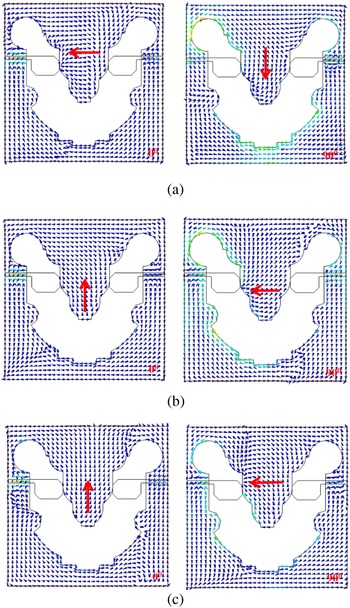
The lower order CP mode generated by bottom ground slot and higher order CP mode generated by two asymmetric ports constitute broadband CP radiation. The CP is mainly obtained by generating two different polarized modes having a phase difference of approximately 90° and equal magnitude ratio of one. As depicted in Fig. 3(a) at 2.0 GHz frequency when port 1 excited, the surface current moves toward –Y direction for 00 phase and toward + X direction when port 1 is fed by 90° phase current. The surface current rotates in a counter-clockwise direction at 2.0, 2.7, and 3.5 GHz frequency respectively. Figure 3(b) depicts that at 2.7 GHz frequency, the vector current flows in the –X direction for 00 phase current and for 90° phase current the surface current moves toward –Y direction. Similarly, at 3.5 GHz frequency the superimposed vector current on ground plane is –X directed at 0° phase and at 90° phase, the surface current is along –Y direction as depicted in Fig. 3(c).
Simulated current distribution of antenna for port 1 at (a) 2.0, (b) 2.7, and (c) 3.5 GHz.

Parametric analysis of proposed antenna
To verify the length–width effect of elements on the performance of antenna in terms of S11, S21, and 3 dB, ARBW is carried out. The width of the feedline and length–width variation effect of middle protruded small square strip is determined and its effect on − 10 dB bandwidth, isolation, and ARBW is verified. The feed width and protruded square strip on the middle are modified to have good enhancement in S11 and ARBW, as the inserted square strip improves the orthogonal current at the bottom plane and selected particular width of a feed gives good impedance matching effect between the elements of antenna which further enhances antenna performance. Some changes done on the common ground slot have a drastic impact on mutual coupling behavior of antennas, ultimately on the isolation values.
Feed width effect on antenna performance
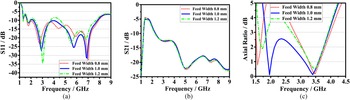
Figure 4 shows the feed-width effect on the performance of antenna. The different values of feed widths are taken as 0.8, 1.0, and 1.2 mm respectively. It has been observed that as the width of feed decreases the − 10 dB return loss of antenna also decreases as shown in Fig. 4(a). It is also found that, there is no such impact on isolation values as shown in Fig. 4(b). Major feed-width impact on the 3 dB ARBW is observed. At the particular selected value of feed width (1.0 mm) the line stays below the 3 dB level, ultimately enhances the ARBW of proposed antenna as shown in Fig. 4(c).
Feed-width effect on (a) S11, (b) S21, and (c) ARBW of proposed antenna.

Effect of middle square strip on antenna performance
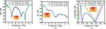
Figure 5 shows the effect of middle square strip on S11, S21, and ARBW of antenna. As seen, the middle square strip has a drastic impact on 3.5–4.5 GHz frequency where the return loss of antenna is varied with the change in length–width of square strip. For smaller values of K1 and K2 the return loss is slightly higher than the larger K1 and K2 values as shown in Fig. 5(a). Similarly, as the K1 and K2 values increase, the isolation values slightly decrease because of the change in mutual coupling effect of common ground slot on both the antennas as shown in Fig. 5(b). ARBW is easily optimized by properly selecting the (K1 x K2) values to achieve the broader CP bandwidth as shown in Fig. 5(c).
Protruded middle square strip effect on (a) S11, (b) S21, and (c) ARBW of proposed antenna.

MIMO performance parameters of antenna
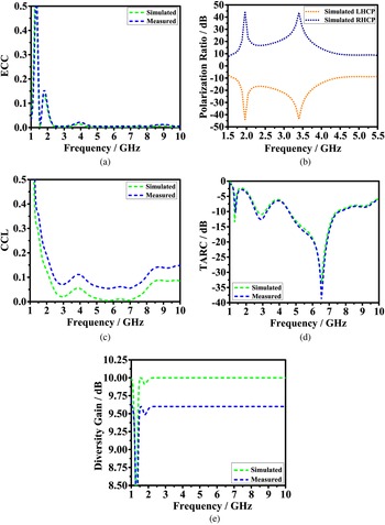
Each MIMO performance parameter requires its own minimum acceptable value likely as channel capacity loss (CCL) and envelope correlation coefficient (ECC) are required to be very small. ECC and CCL parameters must be less than 0.5 [Reference Amin, Saleem, Shabbir, Bilal, Shafique, Rehman, Bilal and Shafique17]. Total active reflection coefficient (TARC) parameter below 0 dB is considered as minimum [Reference Jafri, Saleem, Shafique and Brown18, Reference Chandel, Gautam and Rambabu19]. Minimum value for diversity gain (DG) must be close to 10 dB level [Reference Amin, Saleem, Shabbir, Bilal, Shafique, Rehman, Bilal and Shafique17]. All these MIMO performance parameters are evaluated by using S-parameters of antenna. ECC parameter is used to find orthogonal polarization diversity performance. CCL is used to obey channel transmission and reception capacity of antenna. TARC gives a clear idea on the overall mutual coupling effect of MIMO antenna. DG parameter investigates the increase in signal to noise interference level. The MIMO performances were verified with these five important parameters. It is found that these five MIMO performance parameters are within the minimum acceptable limits discussed above.
Figure 6 shows simulated versus measured MIMO performance parameters. Figure 6(a) shows the ECC of proposed antenna. Both simulated and measured ECC values are less than 0.2 by considering the 3 dB ARBW of antenna. Polarization ratio defines the polarization purity of a MIMO antenna. The simulated polarization ratio curve depicts that both the polarizations are identical to each other as shown in Fig. 6(b). Minimum polarization ratio value of 10 dB is obtained by considering the ARBW. The simulated and measured CCL values are less than 0.2 within the operational bandwidth of antenna shown in Fig. 6(c). Minimum TARC value of 0 dB is achieved by considering the entire bandwidth of antenna depicted in Fig. 6(d). The simulated DG is nearer to 10 dB while the measured graph shows more than 9.6 dB compared with 3 dB ARBW of antenna as shown in Fig. 6(e).
Simulated versus measured (a) ECC, (b) polarization ratio, (c) CCL, (d) TARC, and (e) DG.

Experimental analysis of proposed antenna
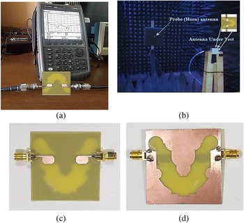
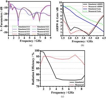
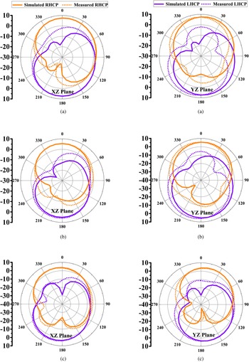
Practical validation of simulated results is obtained by fabricating it using the same substrate material used for simulation analysis. The low cost FR-4 material is selected for designing the proposed MIMO antenna, because the material shows more robustness toward environmental changes and it is a very good heat-absorbing material. Figures 7(c) and 7(d) depict the top and bottom side view of the proposed fabricated geometry of CP MIMO antenna. The gain, ARBW, radiation efficiency, and radiation pattern can be only tested using anechoic chamber because of the reference antenna requirement. To check the proposed antenna performances, the reference antenna which is a circularly polarized horn antenna is placed in front of the designed antenna to have that far-field measurements to clearly verify the measured gain, ARBW, radiation pattern, and radiation efficiency of the proposed antenna under test. The antenna is covered by Antenna Under Test (AUT) unit as shown in Fig. 7(b) to have a low effect of surrounding microwave components on antenna performances during measurements which is shown here clearly. Figure 8 depicts the simulated and measured graphs for S11, radiation efficiency, ARBW, and gain. The 3 dB ARBW, efficiency, and gain are measured using anechoic chamber to perform measured result analysis of antenna. All the S-parameters are measured using Vector Network Analyzer (VNA) with model No.- N9925A. Measured results of S11 shown in Fig. 8(a) and VNA S11 results shown in Fig. 7(a) slightly deteriorate because of surrounding interferences and noises present during VNA testing. The measured S11 < −10 dB graph ranges from 1.70 to 8.00 GHz (6.30 GHz). Simulated and measured S21 and S12 graphs are very well matched with the tested results. Simulated 3 dB ARBW covers from 1.82 to 3.92 GHz while the measured results cover from 1.81 to 3.87 GHz (2.06 GHz). Compared with simulated ARBW, measured ARBW is much closer to 0 dB level which ultimately improves the polarization ratio and orthogonal diversity function of antenna shown in Fig. 8(b). Figure 8(c) depicts simulated versus measured antenna efficiency. During simulation, radiation efficiency of antenna is very close to 100% which is practically impossible to achieve. The simulated radiation efficiency plot is obtained by using tanh function rather than using the abs function to easily fit both simulated and measured plots of radiation efficiency into one plot. Along with some manufacturing tolerances, measurement errors during testing which are also the bad effect of soldering on feed-line structure give rise to variation in simulated and measured efficiency of antenna. Measured radiation efficiency is plotted using abs function. The measured graph depicts that antenna has more than 93% radiation efficiency by considering the entire bandwidth of antenna. The gain is a productive sum of efficiency and antenna directivity. Conversely, the simulated and measured gain values deteriorate slightly. The measured gain is slightly higher than that of simulated gain depicted in Fig. 8(b). Simulated and measured gain values differ by 1 dBic level for each frequency within the ARBW of antenna. Measured results depict peak gain of 8.8 dBic at the lower frequency side of ARBW. The gain value changes from 8.8 to 4.0 dBic within the ARBW. Figure 9 shows simulated and measured radiation pattern for both xz and yz planes. The simulated radiation pattern covers smaller area in comparison with measured LHCP and RHCP radiation plots because measured gain is slightly higher than simulated one. RHCP component leads LHCP component when we excite port 1 and LHCP component leads RHCP component if we excite port 2. Because of antenna design symmetry, both the polarizations are almost symmetrical in every xz and yz plane for each frequency. These two LHCP and RHCP components can easily capture the entire radiation plot which increases total coverage area required for antenna's polarization. The simulated cross-polarization difference between two components is greater than 20, 17, and 30 dB in both planes for 2.0, 2.7, and 3.5 GHz respectively. Radiation patterns depicted in Figs 9(b) and 9(c) slightly deteriorate from broadside direction causing lower value of gain in the upper frequency side of ARBW. Table 2 shows that proposed antenna has size compactness, high peak gain, stable radiation efficiency, and widest IBW.
(a) VNA measurements, (b) anechoic chamber measurements, (c) top, and (d) bottom view of antenna geometry.

Simulated versus measured results of (a) S-parameters, (b) ARBW and gain, and (c) antenna radiation efficiency.

Simulated versus measured antenna radiation pattern for port 1 at (a) 2.0, (b) 2.7, and (c) 3.5 GHz respectively.

Comparison between different broadband antennas

Conclusion
A compact broadband 2 × 2 MIMO array antenna for mid-band 5G wireless application or indoor/outdoor remote access application is proposed. By protruding polyline and square strips on the outer and inner surface of V ground slot it is easy to achieve good enhancement in gain, radiation efficiency, and bandwidth of antenna. The patches cut on edges also have good impact on gain. The impedance bandwidth from 1.70 to 8.00 GHz (6.30 GHz), radiation efficiency of more than 93%, and peak gain of 8.8 dBic are achieved. The radiation pattern shows good CP performance within 3 dB operating band of CP antenna. The gain is nearly stable and it varies from 8.8 to 4.0 dBic by considering the 3 dB ARBW. MIMO performance parameters obey that proposed CP antenna has trustworthy MIMO performance which gives suitability for the 5G wireless application.
Acknowledgements
The authors thank the journal editors and the unknown reviewers for reviewing the research work and providing insightful suggestions to improve the quality of the work.
Conflict of interest
None.
 Aniket Gunjal (graduate student member, IEEE) obtained bachelor's degree in electronics and telecommunication from MET Institute of Engineering, affiliated to Savitribai Phule Pune University (SPPU), Pune, Maharashtra, India, in 2014. He earned master's degree in microwave engineering from SPPU, Pune, Maharashtra, India, in 2016, and now he is pursuing Ph.D. degree in microwave engineering from Symbiosis Institute of Technology, Symbiosis International (Deemed University), Lavale, Pune, India. He is the author of many research articles. His research interest includes the multiple input, multiple output antennas, 5G smartphone antennas, slot antennas, mobile communication, satellite radar applications, wireless access applications, and filters. His major focus is on designing antennas based on the 5G technology and its services.
 Ujwala A. Kshirsagar is an associate professor skilled in internet of things, very large-scale integration, VLSI and embedded system design. A life-long learner with a strong educational background holding master's degree, M.E. in digital electronics and Ph.D. in VLSI technology from Sant Gadge Baba Amravati University, Amravati, India. She is currently working as an associate professor in the Department of Electronics and Tele communication from March 2020 at Symbiosis International University, India. Earlier she was professor and dean at H.V.P. M's College of Engineering and Technology, Amaravati, India from 2003. She is a distinguished academician with 20 years of experience as a researcher and her areas of research include IoT, VLSI and embedded system design and micro/nano electronics manufacturing. She has worked on different analog and digital applications using VLSI Technology, Electronics health care applications using IoT and embedded systems. She has completed six funding projects in the field of nano electronics manufacturing sponsored by Government of India and MeitY. She is the recipient of three national awards for outstanding research in advanced electronics manufacturing. She has published several research papers and are showcased in many refereed journals and conferences. Kshirasagar has published more than 50 international journal papers including Scopus, Web of Science with two best paper awards. She also has two patents to her credit and a book published by an international publisher, Germany. She has served as a resource personnel in many workshops, STTPs and Conferences at national and international levels. She also has delivered lectures on “Future Trends in Technology”, “VLSI Technology and Its Applications” and “Futuristic Technology for Industry 4.0” in various engineering colleges throughout India.