





Impact Statement
This work demonstrates a practical framework for reliably localizing tendon breakage in prestressed concrete structures using high-resolution fiber-optic sensors combined with computational modeling. By embedding uncertainty directly into material and interface models, the approach allows predictions to be transferred to new structural configurations without additional testing, improving confidence in simulation-based assessments. Influence- and separability-based analyses identify which sensor measurements are most informative, guiding monitoring strategies and highlighting where models are most trustworthy. The methodology enhances transparency, reliability, and decision-making in structural health monitoring, offering industry-relevant tools for understanding complex behavior, optimizing sensor deployment, and assessing risk under uncertainty.
1. Introduction
Understanding the location of tendon breakage in prestressed concrete members is essential for assessing structural integrity (Sieradzki and Newman, Reference Sieradzki and Newman1987), guiding emergency interventions, and designing effective monitoring strategies within Structural Health Monitoring (SHM) (Farrar and Worden, Reference Farrar and Worden2007; Bergmeister et al., Reference Bergmeister, Mark, Österreicher, Sanio, Heek, Krawtschuk, Strauss and Ahrens2015; Richter et al., Reference Richter, Will, Herbers and Marx2025). In recent years, SHM approaches have therefore gained popularity for extending the life of critical structures such as bridges (Becks et al., Reference Becks, Lippold, Winkler, Moeller, Rohrer, Leusmann, Anton, Sprenger, Kähler, Rudenko, Arcones, Koutsourelakis, Unger, Weiser, Petryna, Schnellenbach-Held, Lowke, Wessels, Lenzen, Zabel, Könke, Claßen and Hegger2024; Herbers et al., Reference Herbers, Bartels, Richter, Collin, Ulbrich, Al-Zuriqat, Geck, Naraniecki, Hahn, Jesse, Smarsly and openLAB2024; Kang et al., Reference Kang, Arcones, Becks, Beetz, Blankenbach, Claßen, Degener, Eisermann, Göbels, Hegger, Hermann, Kähler, Peralta, Petryna, Schnellenbach-Held, Schulz, Smarsly, Sönmez, Sprenger, Unger, Vassilev, Weiser and Marx2025). Recent studies have explored both data-driven and probabilistic approaches for the assessment of prestressed concrete structures. Machine learning techniques were applied to predict the loss of prestressing forces (Zhang et al., Reference Zhang, Guo and Xu2023; Calò et al., Reference Calò, Ruggieri, Buitrago, Nettis, Adam and Uva2025), while probabilistic data-driven frameworks were employed to evaluate the failure probability of prestressed concrete bridges considering tendon corrosion (Nettis et al., Reference Nettis, Nettis, Ruggieri and Uva2024). However, many data-driven approaches rely on representative training data and often provide limited physical interpretability and uncertainty quantification when extrapolated to configurations that differ from those used during model development. For tendon breakage, however, destructive experiments on operated structures cannot be performed, making direct calibration or validation of mechanical models against in situ tendon failures infeasible (Pirskawetz and Schmidt, Reference Pirskawetz and Schmidt2023). As a result, model calibration must rely on controlled laboratory experiments, where tendon breakage can be safely induced and instrumented. The central challenge is therefore not only to calibrate a model to experimental data, but to do so in a way that allows reliable propagation of uncertainties from laboratory-scale tests to simulations of real structural systems, where tendon breakage localization is ultimately required.
In particular, tendon breakage produces abrupt and highly localized redistribution of strains that propagates along the member. These strain changes can be captured using a spatial grid of distributed fiber-optic sensors (DFOS) (Paul et al., Reference Paul, Sanio and Mark2024b), which provides high-resolution, full-field strain change profiles (Barrias et al., Reference Barrias, Casas and Villalba2016). Such data contain rich information about load transfer mechanisms and bond–slip behavior, making DFOS a powerful sensing technology for tendon-related damage assessment. However, leveraging dense DFOS measurements for tendon breakage localization requires uncertainty-aware methodologies capable of reconciling measurement noise, nonlinear physics, and modeling errors, particularly when results must be transferred beyond the experimental configuration.
A natural framework for simulating the tendon–concrete interaction (Ayoub and Filippou, Reference Ayoub and Filippou2010; Abdelatif et al., Reference Abdelatif, Owen and Hussein2017) and the resulting strain redistribution after breakage (Seiffert and Jensen, Reference Seiffert and Jensen2019; Paul et al., Reference Paul, Sanio and Mark2025) is provided by Finite element models (FEM). Yet, even detailed nonlinear FEMs are affected by model-form uncertainty (MFU) due to idealized constitutive laws, uncertain boundary conditions, and geometric simplifications. When calibration is performed solely against laboratory data, these deficiencies can lead to biased or overconfident predictions if not explicitly accounted for. Discrepancy-based approaches such as the Kennedy–O’Hagan (KOH) formulation (Kennedy and O’Hagan, Reference Kennedy and O’Hagan2001) can improve calibration fidelity in the experimental configuration (Arcones et al., Reference Arcones, Weiser, Koutsourelakis and Unger2024), but the inferred discrepancy terms are tied to the calibration setup and do not naturally transfer to new structural configurations, limiting their usefulness for real-world tendon breakage localization.
To overcome this limitation, embedded MFU is adopted, whereby uncertainty is absorbed directly into an enlarged stochastic parameterization of the model (Sargsyan et al., Reference Sargsyan, Najm and Ghanem2015; Sargsyan et al., Reference Sargsyan, Huan and Najm2019). For tendon-breakage problems, sensitivity studies indicate that the Young’s modulus of the concrete matrix plays a dominant role in controlling the strain response (Paul et al., Reference Paul, Sanio and Mark2026). Treating this modulus as a stochastic variable allows MFU to be represented within the constitutive behavior itself, enabling Bayesian inference approaches to jointly estimate physical parameters and model uncertainty. This embedded representation produces probabilistic parameter descriptions that can be meaningfully transferred from laboratory experiments to simulations of real structural systems without relying on non-transferable discrepancy corrections.
Bayesian calibration involving both deterministic and stochastic parameters requires repeated model evaluations, which are computationally prohibitive for detailed nonlinear FEMs. Gaussian Process (GP) surrogates are therefore employed to emulate FEM responses with quantified predictive uncertainty (Rasmussen, Reference Rasmussen2006), enabling efficient assimilation of full-field DFOS data and uncertainty propagation. Beyond calibration, the framework supports diagnostic analyses. A
$ \phi $
 -divergence-based influence analysis (Weiss, Reference Weiss1996) identifies which DFOS measurements most strongly affect posterior distributions, providing insight into sensor informativeness and model adequacy. This data-centric diagnostic capability is essential for improving physical models in complex structural systems.
As demonstrated in previous studies on small-scale laboratory tests (Paul et al., Reference Paul, Sanio and Mark2025), structural-scale tests (de Domenico et al., Reference de Domenico, Shamsaddinlou, Maugeri, Longo, Messina, Recupero, La Mazza, Longo, Darò and Mancini2026; Sträter et al., Reference Sträter, Clauß, Ahrens and Mark2026), or tests on existing structures (Burger et al., Reference Burger, Betz, Richter, Herbers, Schramm, Diers, Schacht, Lingemann, Marx and Fischer2024; Fiedler and Marx, Reference Fiedler and Marx2026), breakage and subsequent re-anchoring of tendons represent a very localized type of damage. This allows the transfer of the embedded stochastic parameters into new FEM models representing more realistic structural configurations, such as T-beam cross-sections or varying tendon embedment depths. This enables the prediction of strain fields in scenarios where no experimental data are available. In particular, comparing predictive distributions across different tendon positions allows the assessment of separability—a measure of how distinguishable different structural configurations, realized by varying embedment depths of the tendons, are under the propagated uncertainty. This is also commonly known as structural identifiability (Bellman and Åström, Reference Bellman and Åström1970). Regions where predictive distributions overlap indicate sensor locations that provide limited information under the current propagated uncertainty, whereas regions with clear separation identify locations where measurements would be most informative for detecting tendon-related anomalies. This can be used for guiding potential sensor placement (Ostachowicz et al., Reference Ostachowicz, Soman and Malinowski2019).
In this work, we present a fully uncertainty-aware workflow that integrates DFOS measurements, FEM modeling, Bayesian inference with embedded MFU, influence diagnostics, and uncertainty transfer from laboratory experiments to full-scale structural simulations. The framework addresses the fundamental SHM challenge of localizing tendon breakage in systems where direct experimental calibration is impossible, providing a rigorous and transferable basis for uncertainty-informed structural assessment.
2. Methodology
The overall workflow used in this study is summarized in Figure 1. The methodology combines surrogate modeling, Bayesian inference, uncertainty quantification, and influence analysis in a unified framework. First, a computational model of the experimental setup is developed. It is approximated using a GP regressor in order to alleviate the cost of repeated high-fidelity simulations (Section 2.4). Using observational data together with the GP surrogate, the model parameters are inferred through a Bayesian calibration procedure that explicitly accounts for MFU (Section 2.1). Based on the resulting uncertainty estimates, an influence analysis is performed to assess the contribution of different data subsets and parameters to the inferred posterior distributions (Section 2.2). This analysis provides insight into dominant sources of discrepancy and supports targeted model improvements. Finally, the inferred parameters and their associated uncertainties are propagated to related prediction tasks in order to assess the robustness of the results under uncertainty (Section 2.3). The application of this methodology to the specific case study of tendon breakage in reinforced concrete is presented in a dedicated section, where the experimental setup, the high-fidelity model, and the corresponding results are described in detail.
Workflow for the parameter updating and transfer of the simulation of tendon breakage in pretensioned concrete.

Figure 1. Long description
The flowchart is organized into three vertical columns.
1. Model development (left column, grey background):
- Top box: Tendon-break experiment, showing a schematic of a concrete beam and a cross-section with three tendons.
- Bottom box: F E M model, showing the same cross-section and a triangular mesh grid.
- Arrows from both boxes point right into the next phase.
2. Parameter updating (middle column, red and blue backgrounds):
- Bottom red box: Gaussian Process, showing a graph with a red curve, blue data points, and a shaded uncertainty region. An arrow points upward to the next box.
- Top red box: Bayesian model updating, showing a probability density graph with two overlapping curves (blue and red). An arrow points right to the next box.
- Blue vertical box: Calibrated model parameters with U Q, showing a joint probability distribution plot with marginal distributions on the top and right axes.
3. Parameter transfer (right column, green background):
- Top box: New structure F E M model, showing a T-shaped beam cross-section and a triangular mesh grid. An arrow points downward.
- Bottom box: Separability assessment, showing a graph with two distinct bell curves and a small shaded area of overlap at the base.
Arrows connect the phases sequentially from left to right, indicating the flow of data from experimental and numerical models through statistical calibration to final structural assessment.
2.1. Bayesian parameter updating under model-form uncertainty
2.1.1. Model calibration
We define the simulation-based forward model as

where
$ \left(\mathbf{x},\boldsymbol{\theta} \right)\in {\mathcal{X}}_f\times \Theta \subset {\mathrm{\mathbb{R}}}^d $
 is a
$ d $
 -dimensional vector of input parameters composed of observation coordinates
$ \mathbf{x} $
 and model parameters
$ \boldsymbol{\theta} $
 and
$ f\left(\boldsymbol{\xi} \right)\in {\mathrm{\mathbb{R}}}^m $
 is the corresponding
$ m $
 -dimensional simulation output. For calibration, we have the observations dataset
$ \mathcal{Y}=\left({\mathbf{x}}_i,{y}_i|i=1,\dots, N\right) $
 or in matrix form
$ \mathcal{Y}=\left(X,\mathbf{y}\right) $
 . Each observation relates to the simulation model
$ f $
 as

where
$ {\delta}_f\left(\mathbf{x}\right) $
 is a discrepancy term between observations and predictions of
$ f $
 due to the MFU and
$ {\varepsilon}_N $
 is some prescribed noise, which will be treated as
$ \varepsilon \sim \mathcal{N}\left(0,{\sigma}_{\varepsilon}^2\right) $
 .
Without MFU, the classical parameter updating problem consists of solving

where
$ \parallel \cdot \parallel $
 is a norm to be defined, typically the Euclidean norm that leads to solving a minimization of the mean-squared error (MSE). Following the common principles of modularization (Bayarri et al., Reference Bayarri, Berger, Paulo, Sacks, Cafeo, Cavendish, Lin and Tu2007), the training of the surrogate and the calibration of the parameters are performed sequentially and independently.
In the Bayesian framework, the main objective is to find the posterior probability distribution of
$ {\boldsymbol{\theta}}^{\ast } $
 given the observations. We start by disregarding the discrepancy term
$ \left({\delta}_f=0\right) $
 and imposing an error structure for the observation vector
$ \mathbf{y} $
 such that it follows a multivariate normal distribution as
$ \mathbf{y}-f\left(X,\boldsymbol{\theta} \right)\sim \mathcal{M}\mathcal{VN}\left(\mathbf{0},{\Sigma}_{\varepsilon}\right) $
 , where
$ {\Sigma}_{\varepsilon } $
 is the covariance matrix equal to
$ {\sigma}_{\varepsilon}^2I $
 for independent normal errors. We obtain then the likelihood distribution as

where
$ \parallel \mathbf{y}-f\left(X,\boldsymbol{\theta} \right){\parallel}_{\Sigma_{\varepsilon}^{-1}}^2 $
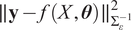 denotes the Euclidean norm of the residuals weighted by the inverse of the covariance of the noise model. One option is directly substituting the model
$ f\left(X,\boldsymbol{\theta} \right) $
 by the mean of its approximation
$ {\mathbf{m}}_{\mathrm{GP}}\left(\boldsymbol{\theta} \right)=\unicode{x1D53C}\left[\tilde{f}\left(X,\boldsymbol{\theta} \right)\right] $
 , where
$ \tilde{f}\left(X,\boldsymbol{\theta} \right) $
 is the GP regression fitted for
$ f\left(X,\boldsymbol{\theta} \right) $
 . The details on the GP implementation are provided in Section 2.4.
Applying Bayes’ theorem, it is possible to obtain the posterior probability distribution of
$ \boldsymbol{\theta} $
 from the likelihood
$ \mathcal{L}\left(\boldsymbol{\theta} \right) $
 and the prior
$ \pi \left(\boldsymbol{\theta} \right) $
 . In particular,

Sampling approaches such as those based on Markov Chain Monte Carlo (MCMC) draw realizations of the posterior distribution by evaluating samples of
$ \boldsymbol{\theta} $
 at Equation 5.
2.1.2. Model form uncertainty
Traditional Bayesian approaches do not treat MFU effectively, as the discrepancy term
$ {\delta}_f(x) $
 is generally disregarded. Under additive Gaussian observation noise with diagonal covariance, Bayesian calibration reduces to a (weighted) least-squares problem, which, in the present case of a scalar diagonal covariance, coincides with ordinary least squares. As a result, the inferred posterior distribution
$ \pi \left(\boldsymbol{\theta} |\mathbf{y}\right) $
 concentrates around the least-squares estimate as the noise level decreases, and any unexplained variability in the observations is necessarily attributed to parameter uncertainty. Consequently, the posterior predictive distribution
$ f\left(X,\boldsymbol{\theta} |\mathbf{y}\right) $
 fails to reflect variability arising from structural model inadequacy, leading to overconfident predictions that do not capture the observed variability (Arcones et al., Reference Arcones, Weiser, Koutsourelakis and Unger2024).
One popular alternative is the framework from Kennedy and O’Hagan (Reference Kennedy and O’Hagan2001), which implements
$ {\delta}_f(x) $
 as a flexible parameterized function that compensates for the discrepancy, generally a GP. However, the
$ {\delta}_f(x) $
 inferred within that framework cannot be propagated to other than systems or datasets than the one used for calibration. A promising alternative is the embedding of the uncertainty within the parameter formulation, as proposed in Sargsyan et al. (Reference Sargsyan, Huan and Najm2019). The model with discrepancies is then reformulated as

where
$ \tilde{\boldsymbol{\theta}} $
 is a stochastic extension of the parameter vector
$ \boldsymbol{\theta} $
 , endowed with a probability density
$ {\pi}_{\overline{\theta}}\left(\tilde{\boldsymbol{\theta}}\right) $
 defined on the parameter space
$ \Theta $
 . This formulation implicitly accounts for the model discrepancy
$ {\delta}_f(x) $
 through variability in the extended parameters. Introducing a probability distribution for
$ \tilde{\boldsymbol{\theta}} $
 follows a hierarchical Bayesian construction and prevents excessive concentration of the posterior distribution of the affected parameters and their associated predictions. The resulting predictive uncertainty can be calibrated to provide a suitable representation of the MFU, provided that the extended model is sufficiently flexible to cover the range of the observations through variations in
$ \tilde{\boldsymbol{\theta}} $
 . The hyperparameters governing the density
$ {\pi}_{\overline{\theta}} $
 are inferred jointly with the original model parameters. In this paper, we follow the methodology developed in Andrés Arcones et al. (Reference Arcones, Weiser, Koutsourelakis and Unger2026), defining explicitly such probability distributions as normal or log-normal, and adding their parameters to the inference. Therefore,
$ {\boldsymbol{\theta}}_{\mathrm{ext}}=\left\{\boldsymbol{\theta}, {\boldsymbol{\theta}}_{\boldsymbol{\delta}}\right\} $
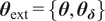 , where
$ {\boldsymbol{\theta}}_{\boldsymbol{\delta}} $
 represents the vector of parameters associated with the stochastic extension for the discrepancy
$ \tilde{\boldsymbol{\theta}} $
 .
2.1.3. Uncertainty propagation
As
$ \tilde{\boldsymbol{\theta}} $
 is a random variable,
$ f\left(x,\tilde{\boldsymbol{\theta}}\right) $
 is also stochastic, which means that the probability distribution
$ {\pi}_{\tilde{\boldsymbol{\theta}}} $
 of
$ \tilde{\boldsymbol{\theta}} $
 must be either sampled or propagated through
$ f $
 for its full description. As is common in embedded approaches—in contrast to hierarchical Bayesian methods—we opt for propagating
$ \tilde{\boldsymbol{\theta}} $
 by using a Polynomial Chaos Expansion (PCE) (Sudret, Reference Sudret2021). For a given coordinate vector
$ \mathbf{x} $
 , we seek a PCE of the form:

where
$ \left\{{\Psi}_{\boldsymbol{\alpha}}\left(\tilde{\boldsymbol{\theta}}\right)\right\} $
 is a multivariate orthogonal polynomial basis with respect to the probability measure of
$ \tilde{\boldsymbol{\theta}} $
 ,
$ \boldsymbol{\alpha} \in {\mathrm{\mathbb{N}}}_0^n $
 is a multi-index defining the total degree of each multivariate polynomial,
$ \mathrm{A}\subset {\mathrm{\mathbb{N}}}_0^n $
 is the finite set of indices used in the expansion (e.g., corresponding to polynomials up to total degree
$ p $
 ),
$ {c}_{\boldsymbol{\alpha}}\left(\mathbf{x}\right)\in \mathrm{\mathbb{R}} $
 are the PCE coefficients, which are functions of the input coordinate
$ \mathbf{x} $
 . The polynomials
$ {\Psi}_{\alpha } $
 are chosen to be orthonormal following Askey’s scheme based on the input distributions of
$ \tilde{\boldsymbol{\theta}} $
 (Xiu and Karniadakis, Reference Xiu and Karniadakis2002) such that
$ \left\langle {\Psi}_{\boldsymbol{\alpha}},{\Psi}_{\boldsymbol{\alpha}}\right\rangle =1 $
 with
$ \left\langle {\Psi}_{\boldsymbol{\alpha}},{\Psi}_{\boldsymbol{\alpha}}\right\rangle ={\int}_{{\mathrm{\mathbb{R}}}^n}{\Psi}_{\boldsymbol{\alpha}}^2\left(\boldsymbol{\theta} \right)\hskip0.1em {\pi}_{\tilde{\boldsymbol{\theta}}}\left(\boldsymbol{\theta} \right)\hskip0.1em d\boldsymbol{\theta} $
 .
To approximate
$ {c}_{\boldsymbol{\alpha}}\left(\mathbf{x}\right) $
 , we use a pseudo-spectral projection approach based on Gaussian quadrature with
$ Q $
 quadrature points, such that the coefficients of the PCE are obtained as

where
$ {\left\{{\boldsymbol{\theta}}^{(q)},{w}^{(q)}\right\}}_{q=1}^Q $
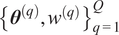 are the quadrature nodes and weights associated with
$ {\pi}_{\tilde{\boldsymbol{\theta}}} $
 . For a collection of input points
$ X=\left\{{\mathbf{x}}^{(1)},\dots, {\mathbf{x}}^{(N)}\right\} $
 , the model is evaluated at each
$ {\mathbf{x}}^{(j)} $
 for all quadrature nodes
$ {\boldsymbol{\theta}}^{(q)} $
 . A single model simulation yields

which allows constructing all
$ {c}_{\boldsymbol{\alpha}}\left({\mathbf{x}}^{(j)}\right) $
 simultaneously for only
$ Q $
 evaluations of the model. As full model evaluations
$ f $
 are typically computationally expensive, evaluations of the mean
$ {\mathbf{m}}_{\mathrm{GP}} $
 of the surrogate model
$ \tilde{f} $
 are used instead. The PCE provides a full surrogate model for the stochastic response
$ {\mathbf{m}}_{\mathrm{GP}}\left(\tilde{\boldsymbol{\theta}}\right)=\unicode{x1D53C}\left[\tilde{f}\left(X,\tilde{\boldsymbol{\theta}}\right)\right] $
 across all input locations
$ X=\left\{{\mathbf{x}}^{(1)},\dots, {\mathbf{x}}^{(N)}\right\} $
 .
The approximation is expressed as

where each
$ {\mathbf{c}}_{\boldsymbol{\alpha}}\in {\mathrm{\mathbb{R}}}^N $
 is a vector of PCE coefficients evaluated at all input points, such as

From this expansion, the mean at the observations
$ {\mathbf{m}}_{\mathrm{PCE}}\left(\boldsymbol{\theta} \right)\in {\mathrm{\mathbb{R}}}^N $
 and the variances at observations
$ {\boldsymbol{\sigma}}_{\mathrm{PCE}}^2\in {\mathrm{\mathbb{R}}}^N $
 of the model response over
$ X $
 are obtained directly as components of the surrogate:


where the square
$ {\mathbf{c}}_{\boldsymbol{\alpha}}^2 $
 is computed component-wise, and therefore the covariance matrix is
$ {\Sigma}_{\mathrm{PCE}}={\boldsymbol{\sigma}}_{\mathrm{PCE}}^2\left({\boldsymbol{\theta}}_{\mathrm{ext}}\right)I $
 , assuming independent outputs. The last expressions follow immediately from the orthogonality of the polynomial basis. Further statistical moments can be extracted, but once the PCE is constructed, it is possible to approximate the full statistical behavior of
$ f\left(X,\tilde{\boldsymbol{\theta}}\right) $
 , without requiring any additional sampling or postprocessing.
Since the response of
$ \tilde{f}\left(X,\tilde{\boldsymbol{\theta}}\right) $
 is stochastic and depends on the extrinsic parameters
$ {\boldsymbol{\theta}}_{\mathrm{ext}} $
 , one can identify those parameters for which the induced variance of
$ f\left(X,\tilde{\boldsymbol{\theta}}\right) $
 provides a quantitative measure of MFU. To do so, we adapt the likelihood term defined in Equation 4 to include the variance of the prediction under the assumption that the response follows a normal distribution. The resulting likelihood is

In a given iteration of an MCMC loop, samples of
$ {\boldsymbol{\theta}}_{\mathrm{ext}} $
 are drawn; then
$ \tilde{\boldsymbol{\theta}} $
 is defined based on them; the PCE for
$ \tilde{f}\left(X,\tilde{\boldsymbol{\theta}}\right) $
 is constructed using evaluations of the forward model at a set of quadrature points; the statistical moments of the PCE
$ {\mathbf{m}}_{\mathrm{PCE}} $
 and
$ {\Sigma}_{\mathrm{PCE}} $
 are computed; and finally the likelihood
$ {\mathcal{L}}_{\mathrm{IN}}\left({\boldsymbol{\theta}}_{\mathrm{ext}}\right) $
 is evaluated to obtain a sample of the posterior distribution
$ \pi \left({\boldsymbol{\theta}}_{\mathrm{ext}}|\mathbf{y}\right) $
 .
2.2. Influence analysis
2.2.1.
$ \phi $
 -divergence with full posterior

Let
$ Y=\left({y}_1,\dots, {y}_n\right) $
 denote the whole dataset of observations. Let
$ S $
 denote a nonempty proper subset of indices
$ \left\{1,\dots, n\right\} $
 and let its complement be
$ {S}^c=\left\{1,\dots, n\right\}\backslash S $
 . We denote by
$ {Y}_S=\left\{{Y}_i:i\in S\right\} $
 and
$ {Y}_{S^c}=\left\{{Y}_i:i\in {S}^c\right\} $
 the corresponding subvectors of observations. We investigate the effect of removing
$ S $
 from the dataset on the posterior distribution of the model parameters. Assuming that
$ \pi \left(\boldsymbol{\theta} |Y\right) $
 has global support, we define the posterior distributions

The influence of
$ S $
 can be quantified using a
$ \phi $
 -divergence (Weiss, Reference Weiss1996). The
$ \phi $
 -divergence between the two probability density functions
$ \pi \left(\boldsymbol{\theta} |Y\right) $
 and
$ \pi \left(\boldsymbol{\theta} |{Y}_{S^c}\right) $
 is defined as

where
$ \phi :{\mathrm{\mathbb{R}}}_0^{+}\to \mathrm{\mathbb{R}} $
 is a convex function satisfying
$ \phi (1)=0 $
 . A common choice for
$ \phi $
 is the reverse Kullback–Leibler (KL) divergence, obtained by setting
$ \phi \left(\cdot \right)=-\log \left(\cdot \right) $
 . For simplification, we will denote by
$ {D}_{\phi }(S) $
 the
$ \phi $
 -divergence of the posterior distribution obtained with the full data
$ Y $
 and after excluding the subset
$ S $
 , using the reverse KL divergence.
This formulation has the advantage that it does not require recomputing the posterior distribution for each subset
$ {Y}_{S^c} $
 . Instead, it can be evaluated directly from posterior samples and their likelihood values (Weiss, Reference Weiss1996; Zhu et al., Reference Zhu, Ibrahim, Cho and Tang2012). The data vector
$ Y=\left({Y}_S,{Y}_{S^c}\right) $
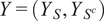 fulfills the chain rule of probability

Therefore, we define the ratio of likelihoods between using all data
$ Y $
 and using only
$ {Y}_{S^c} $
 as

Then, applying Bayes’ law and Equation 18,


where
$ {\unicode{x1D53C}}_{\boldsymbol{\theta} \mid Y} $
 denotes expectation with respect to the posterior distribution
$ \pi \left(\boldsymbol{\theta} |Y\right) $
 . Substituting this expression into the definition of
$ {D}_{\phi }(S) $
 and simplifying yields the following expression for the influence of
$ S $


Finally, substituting the influence function
$ \phi (u)=-\log (u) $
 we get

This influence measure can be computed for different sets
$ S $
 to evaluate the relative influence of some observations over others on the inferred posterior. See Appendix B.1 for a stable estimation of the global influence from posterior samples.
2.2.2.
$ \phi $
-divergence on the marginal posterior using kernel density estimation

We are interested in extending the formulation of
$ {D}_{\phi } $
 of Equation 25 for a single parameter component
$ {\theta}_j $
 . Since
$ {\pi}_S\left(\boldsymbol{\theta} \right) $
 is not a probability density, marginalization must be defined with respect to the joint posterior distribution. We therefore consider the conditional posterior expectation of
$ {\pi}_S\left(\boldsymbol{\theta} \right) $
 given
$ {\theta}_j $
 . The posterior expectation conditional on the value of
$ {\theta}_j $
 is

where
$ {\theta}_{-j} $
 denotes all components except
$ {\theta}_j $
 . An alternative would be to marginalize the perturbed
$ \pi \left({Y}_{S^c}|\boldsymbol{\theta} \right) $
 and reference posteriors
$ \pi \left(Y|\boldsymbol{\theta} \right) $
 with respect to
$ {\theta}_{-j} $
 and compute a divergence directly between the resulting marginal distributions of
$ {\theta}_j $
 .
In practice, we approximate
$ {\pi}_S^{(j)}\left({\theta}_j\right) $
 from a posterior sample
$ {\left\{{\boldsymbol{\theta}}^{(i)}\right\}}_{i=1}^N $
 using a one-dimensional weighted kernel density in the
$ {\theta}_j $
 coordinate (Hastie et al., Reference Hastie, Tibshirani and Friedman2009). Let
$ K:\mathrm{\mathbb{R}}\to {\mathrm{\mathbb{R}}}^{+} $
 be a kernel and
$ h>0 $
 the bandwidth. We define the Gaussian kernel
$ {K}_h(u)=\frac{1}{h}K\left(\frac{u}{h}\right) $
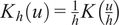 with
$ K(u)={\left(2\pi \right)}^{-1/2}{e}^{-{u}^2/2} $
 . Using sample values
$ {\theta}_j^{(i)} $
 and weights
$ {w}_i\propto {\pi}_S\left({\boldsymbol{\theta}}^{(i)}\right) $
 computed from full-sample likelihoods, we compute the Nadaraya–Watson estimator (Nadaraya, Reference Nadaraya1964; Watson, Reference Watson1964) of the conditional expectation as

where the bandwidth
$ h $
 is chosen following Scott’s rule (Scott, Reference Scott2008). We then insert this smoothed conditional ratio into the
$ \phi $
 -divergence influence functional. The marginal influence for component
$ j $
 is

See Appendix B.2 for a stable estimation of the marginal influence from posterior samples using the KDE approach.
2.2.3.
$ \phi $
-divergence on the marginal posterior using fixed-mean parameter estimators

It is also of interest to compute the marginal influence on one parameter when the others are fixed to their estimated values. In this case, this marginal influence is approximated by fixing them at the mean of their posterior samples. We first compute such mean of
$ {\theta}_{-j} $
 as

The fixed-mean perturbation as a function of
$ {\theta}_j $
 is the pointwise evaluation

Using this plug-in perturbation, we define the fixed-mean influence

See Appendix B.3 for a stable estimation of the marginal influence from posterior samples using the fixed-mean approach.
2.3. Uncertainty propagation, separability and identifiability
Unlike classical approaches, the embedded formulation enables the propagation of quantified MFU through an extended parameter set. Let
$ g $
 be a real-valued map, analogous to
$ f $
 , defined as

where
$ \mathbf{x}\in {\mathcal{X}}_g $
 denotes the input coordinates at which the model response is evaluated,
$ \boldsymbol{\theta} \in {\Theta}_g\subseteq \Theta $
 is the vector of parameters previously calibrated using model
$ f $
 , and
$ \boldsymbol{\lambda} \in {\Lambda}_g $
 is a vector of additional parameters that are not identified in the calibration stage. In contrast to
$ \boldsymbol{\theta} $
 , the parameters
$ \boldsymbol{\lambda} $
 are quantities of direct interest that must be inferred from measurement data in the physical system, for example, damage-related state variables.
The model
$ g $
 represents a downstream prediction task in which the calibrated parameters
$ \boldsymbol{\theta} $
 are reused under a different modeling context. When the parameters
$ \boldsymbol{\theta} $
 are calibrated with embedded uncertainties, they are represented by random variables
$ \tilde{\boldsymbol{\theta}} $
 , rendering the model response
$ g\left(\mathbf{x},\tilde{\boldsymbol{\theta}},\boldsymbol{\lambda} \right) $
 inherently stochastic. For each fixed value of
$ \boldsymbol{\lambda} $
 , the uncertainty in
$ \tilde{\boldsymbol{\theta}} $
 induces a predictive distribution of the model output. The central objective is to assess how this propagated uncertainty affects the ability to distinguish between different candidate values of
$ \boldsymbol{\lambda} $
 based on the resulting predictive distributions.
In this work, the model
$ g $
 is a FEM of a reinforced concrete beam used to investigate whether measurements from a SHM system can be linked to corresponding values of the model-state parameters
$ \boldsymbol{\lambda} $
 . Specifically,
$ \boldsymbol{\lambda} $
 encodes the location of a tendon failure, parameterized through the depth of the tendon break. The predictive distributions of the structural response for different values of
$ \boldsymbol{\lambda} $
 are compared against observed strain patterns to evaluate how accurately the damaged tendon can be identified in the presence of embedded MFU. As in the calibration stage, a PCE surrogate is employed to approximate the stochastic model response, following Equations 7–13. This surrogate enables efficient propagation of the uncertainty in
$ \tilde{\boldsymbol{\theta}} $
 for each candidate value of
$ \boldsymbol{\lambda} $
 , yielding the predictive distributions required for subsequent identifiability and influence analyses.
Using the calibrated parameter set
$ \boldsymbol{\theta} $
 , we simulate system responses
$ g\left(\mathbf{x},\tilde{\boldsymbol{\theta}},\boldsymbol{\lambda} \right) $
 for various hypothesized values of
$ \boldsymbol{\lambda} $
 . Running these simulations over a range of possible breakage locations generates a family of predictive distributions, each representing the expected system response for a particular damage scenario. These predictive distributions provide the basis for defining detection thresholds within the monitoring framework, which can be tailored to specific spatial locations
$ \mathbf{x} $
 in the structure. A diagram of the proposed workflow is represented in Figure 2.
Flow diagram of uncertainty propagation and identifiability analysis. The calibrated parameters
$ {\boldsymbol{\theta}}^{\ast } $
 are extended with a set of non-calibrated parameters
$ \boldsymbol{\lambda} $
 , propagated through the FEM model
$ g $
 , approximated via PCEs, and used to train GP surrogates for separability analysis.

Figure 2. Long description
The flowchart is divided into three vertical sections.
1. Calibrated Section (Top, Blue):
- Left: A contour plot showing the posterior distribution pi of theta super asterisk given y, with marginal distributions on the top and right axes.
- Right: Two sequential boxes. The first is labeled Posterior pi of theta super asterisk given y. An arrow points down to the second box labeled M A P: theta hat super asterisk.
2. Non-calibrated Section (Middle, Red):
- Left: A diagram of a T-shaped structural component with a central hole and a corresponding triangular mesh grid, labeled g of x, theta sub ext.
- Right: Two sequential boxes. The first is labeled Extend: theta sub ext equals the set of theta hat super asterisk and lambda. An arrow points down to the second box labeled F E M: g of x, theta sub ext.
3. Propagated Section (Bottom, Green):
- Left: A graph showing two overlapping green bell curves labeled G sub x of lambda sub 0 and G sub x of lambda sub 0 plus delta lambda. The overlapping area contains a question mark.
- Right: Three sequential boxes. The first is labeled Fit P C E at each x, lambda: m sub P C E of x, lambda, sigma squared sub P C E of x, lambda. The second box is labeled Gaussian Process surrogate with Inputs: x, lambda and Outputs: m sub P C E of x, lambda, sigma squared sub P C E of x, lambda. The final box at the bottom is labeled Separability: lambda super asterisk sub 0 of x, delta lambda sub min of x.
However, the MFU embedded in
$ \tilde{\boldsymbol{\theta}} $
 leads to overlapping output distributions for different values of
$ \boldsymbol{\lambda} $
 . When the predictive distributions for
$ g\left(\mathbf{x},\tilde{\boldsymbol{\theta}},{\boldsymbol{\lambda}}_1\right) $
 and
$ g\left(\mathbf{x},\tilde{\boldsymbol{\theta}},{\boldsymbol{\lambda}}_2\right) $
 , corresponding to
$ {\boldsymbol{\lambda}}_1 $
 and
$ {\boldsymbol{\lambda}}_2={\boldsymbol{\lambda}}_1+\Delta \boldsymbol{\lambda} $
 , are not statistically distinguishable, it becomes impossible to unambiguously infer the change in
$ \boldsymbol{\lambda} $
 from the observed data. This is the essence of the identifiability problem. Therefore, a central objective is to quantify the minimal detectable perturbation
$ \Delta {\boldsymbol{\lambda}}_{\mathrm{min}} $
 such that the induced change in system response exceeds the uncertainty envelope defined by the calibrated model. This enables a principled definition of detection thresholds that are both sensitive and robust, grounded in the probabilistic structure of the FEM response. The identifiability of a change in the parameter vector
$ \boldsymbol{\lambda} $
 depends not only on the magnitude of the perturbation
$ \Delta \boldsymbol{\lambda} $
 , but also on the current operating point
$ {\boldsymbol{\lambda}}_0 $
 and the direction of change (i.e., whether
$ {\boldsymbol{\lambda}}_0\pm \Delta \boldsymbol{\lambda} $
 ). Due to the nonlinear and probabilistic nature of the forward model
$ g\left(\mathbf{x},\tilde{\boldsymbol{\theta}},\boldsymbol{\lambda} \right) $
 , the propagated response distributions may differ significantly depending on both
$ {\boldsymbol{\lambda}}_0 $
 and the sign of the perturbation.
The identifiability analysis is conducted locally at each point
$ \mathbf{x} $
 in the spatial domain. For a given
$ \mathbf{x} $
 , the objective is to determine the smallest perturbation
$ \Delta \boldsymbol{\lambda} $
 that leads to a statistically distinguishable change in the model response, as well as the corresponding parameter configuration
$ {\boldsymbol{\lambda}}_0^{\ast } $
 for which this minimal change is most difficult to detect. Let the response distribution at
$ \mathbf{x} $
 be defined as
$ {\mathrm{G}}_{\mathbf{x}}\left(\boldsymbol{\lambda} \right)=g\left(\mathbf{x},\tilde{\boldsymbol{\theta}},\boldsymbol{\lambda} \right) $
 . The chosen identifiability criterion is based on the principle of non-overlap of the confidence intervals at 95%. We define the spatially-localized maximin optimization problem as

Here,
$ \Delta {\boldsymbol{\lambda}}_{\mathrm{min}}\left(\mathbf{x}\right) $
 is the smallest detectable parameter shift at point
$ \mathbf{x} $
 and
$ {\boldsymbol{\lambda}}_0^{\ast}\left(\mathbf{x}\right) $
 is the least favorable configuration, that is, the point in parameter space where distinguishability is hardest under the confidence interval criterion. This formulation ensures that detection thresholds are defined locally and conservatively, based on the worst-case identifiability scenario at each spatial location. In practical terms, solving this problem enables spatially varying sensitivity maps to be constructed, guiding sensor placement and interpretation of system responses under monitoring conditions.
Due to the high computational cost of evaluating the FEM model
$ g\left(\mathbf{x},\boldsymbol{\theta}, \boldsymbol{\lambda} \right) $
 , a surrogate modeling strategy is adopted to make the identifiability optimization tractable. The surrogate captures the dependence of the distribution of
$ g $
 on the parameters
$ \boldsymbol{\lambda} $
 , accounting for the uncertainty introduced by the parameters
$ \tilde{\boldsymbol{\theta}} $
 . For each pair
$ \left(\mathbf{x},\boldsymbol{\lambda} \right) $
 , the distribution
$ {\mathcal{G}}_{\mathbf{x}}\left(\boldsymbol{\lambda} \right)=g\left(\mathbf{x},\tilde{\boldsymbol{\theta}},\boldsymbol{\lambda} \right) $
 is approximated using a PCE with
$ \tilde{\boldsymbol{\theta}} $
 as input, yielding the conditional mean
$ {\mathbf{m}}_{\mathrm{PCE}}\left(\mathbf{x},\boldsymbol{\lambda} \right) $
 and variance
$ {\boldsymbol{\sigma}}_{\mathrm{PCE}}^2\left(\mathbf{x},\boldsymbol{\lambda} \right) $
 of the model response as formulated in Equations 7–13. These statistics are then modeled using two independent GP regressors, one for the mean and one for the variance, whose implementation details will be reviewed in Section 2.4. The training dataset for the GP surrogates is constructed as follows: a set of spatial locations
$ X={\left[{\mathbf{x}}_i\right]}_{i=1}^{N_x} $
 is selected as a subset of the mesh nodes used in the FEM simulation. Then, a discrete grid
$ {\left\{{\boldsymbol{\lambda}}_j\right\}}_{j=1}^{N_{\lambda }}\subset {\Lambda}_g $
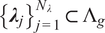 is chosen to cover the admissible domain
$ {\Lambda}_g $
 of the uncertain parameters. For each training pair
$ \left({\mathbf{x}}_i,{\boldsymbol{\lambda}}_j\right) $
 , the corresponding PCE is constructed to compute the mean and variance of
$ {\mathcal{G}}_{\mathbf{x}}\left(\boldsymbol{\lambda} \right) $
 , which are then used to train the GPs. This dataset can be formulated as

Only
$ {N}_{\lambda}\cdot {N}_Q $
 evaluations of
$ g $
 are required, where
$ {N}_Q $
 is the number of quadrature points for the PCE. Once trained, the GPs provide efficient predictions
$ {\mathbf{m}}_{\mathrm{PCE}}\left(\mathbf{x},\boldsymbol{\lambda} \right) $
 and
$ {\boldsymbol{\sigma}}_{\mathrm{PCE}}^2\left(\mathbf{x},\boldsymbol{\lambda} \right) $
 at any
$ \left(\mathbf{x},\boldsymbol{\lambda} \right) $
 pair within the domain of interest. The 95% confidence intervals for the response distributions are then approximated as

where
$ {\tilde{\mathbf{m}}}_{\mathrm{PCE}} $
 and
$ {\tilde{\boldsymbol{\sigma}}}_{\mathrm{PCE}}^2 $
 are the statistical moments estimated by their respective GPs. The variance introduced by the GP is disregarded for simplicity, as
$ {\mathcal{D}}_{\mathrm{train}} $
 is sufficiently dense. The confidence interval approximation of Equation 35 can be directly plugged into the optimization problem in Equation 33. The domain
$ {\Lambda}_g $
 is discretized for the maximization part of the optimization problem, choosing the same fixed grid
$ {\left\{{\boldsymbol{\lambda}}_j\right\}}_{j=1}^{N_{\lambda }} $
 as used in the GP training, thereby improving the evaluation efficiency. The minimization problem for
$ \Delta \boldsymbol{\lambda} $
 is solved using the Nelder–Mead algorithm, while the maximization of
$ {\boldsymbol{\lambda}}_0 $
 is performed by comparison in the grid. This formulation enables efficient computation of the minimal detectable changes across the spatial domain, making it feasible to generate full-field maps of identifiability under uncertainty.
If separability is not achieved within a predefined maximum perturbation
$ \Delta {\lambda}_{\mathrm{max}} $
 , the optimization problem in Equation 33 is infeasible. Even in that case, we can extract some insight from partial solutions. To address this, we first check separability at
$ \lambda \pm \Delta {\lambda}_{\mathrm{max}} $
 for each candidate
$ \lambda $
 . If separability is already satisfied at this level, then the optimization proceeds as usual. Otherwise, we fix
$ \Delta \lambda =\Delta {\lambda}_{\mathrm{max}} $
 and quantify the degree of indistinguishability by computing the overlap between the two distributions. The overlap integral is computed to measure the amount of shared probability mass between the two distributions corresponding to
$ \lambda $
 and
$ \lambda \pm \Delta {\lambda}_{\mathrm{max}} $
 as

where
$ y $
 represents the output of the (i.e., the support of
$ {\mathcal{G}}_{\mathbf{x}} $
 ) over which the probability mass is defined. In practice,
$ {\mathcal{G}}_{\mathbf{x}} $
 is modeled as a normal random variable defined by the PCE, and the integrals are calculated by numerical integration in the range of
$ {\tilde{\mathbf{m}}}_{\mathrm{PCE}}\pm 4{\tilde{\boldsymbol{\sigma}}}_{\mathrm{PCE}}^2 $
 , truncating the distribution everywhere else.
From the collection of overlaps across the parameter grid, summary statistics can be extracted as

These values provide complementary information:
$ {O}_{\mathrm{min}} $
 indicates the best-case separability,
$ {O}_{\mathrm{max}} $
 the worst-case indistinguishability, and
$ {R}_O $
 quantifies the variability of overlap across
$ {\Lambda}_g $
 . The complete procedure is summarized in Algorithm 1.
Algorithm 1 Minimal detectable change with separability check at
$ \Delta {\lambda}_{\mathrm{max}} $

Require: Spatial nodes
$ X={\left\{{\mathbf{x}}_i\right\}}_{i=1}^{N_x} $
 , parameter grid
$ {\Lambda}_g={\left\{{\lambda}_j\right\}}_{j=1}^{N_{\lambda }} $
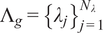 , GP surrogates for
$ {\tilde{\mathbf{m}}}_{\mathrm{PCE}},{\tilde{\sigma}}_{\mathrm{PCE}}^2 $
 , maximum perturbation
$ \Delta {\lambda}_{\mathrm{max}} $
 , optimizer
$ \mathcal{O} $
 .
Ensure: For each
$ {\mathbf{x}}_i $
 :
$ \left({\boldsymbol{\lambda}}_0^{\ast}\left({\mathbf{x}}_i\right),\Delta {\boldsymbol{\lambda}}_{\mathrm{min}}\left({\mathbf{x}}_i\right)\right) $
 , overlap map
$ O\left({\mathbf{x}}_i,{\lambda}_j\right) $
 , and
$ \left({O}_{\mathrm{min}},{O}_{\mathrm{max}},{R}_O\right) $
 .
-
1: for each spatial node $ {\mathbf{x}}_i\in X $
do -
2: for each parameter $ {\lambda}_j\in {\Lambda}_g $
do -
3: Check separability at $ \Delta {\lambda}_{\mathrm{max}} $
:$$ \mathrm{S}\mathrm{e}\mathrm{p}\mathrm{a}\mathrm{r}\mathrm{a}\mathrm{b}\mathrm{l}\mathrm{e}\leftarrow \left\{\begin{array}{l}{\mathrm{CI}}_{0.95}[{\mathcal{G}}_{{\mathbf{x}}_i}({\lambda}_j)]\cap {\mathrm{CI}}_{0.95}[{\mathcal{G}}_{{\mathbf{x}}_i}({\lambda}_j+\Delta {\lambda}_{\mathrm{max}})]\overset{?}{=}\mathrm{\varnothing},\\ {}{\mathrm{CI}}_{0.95}[{\mathcal{G}}_{{\mathbf{x}}_i}({\lambda}_j)]\cap {\mathrm{CI}}_{0.95}[{\mathcal{G}}_{{\mathbf{x}}_i}({\lambda}_j-\Delta {\lambda}_{\mathrm{max}})]\overset{?}{=}\mathrm{\varnothing}.\end{array},\operatorname{}\right. $$
-
4: end for
-
5: if $ \mathrm{Separable}\forall {\lambda}_j\in {\Lambda}_g $
then -
6: {Perform optimization}
-
7: Solve Eq. (33) with optimizer $ \mathcal{O} $
to obtain
$ \left({\boldsymbol{\lambda}}_0^{\ast}\left({\mathbf{x}}_i\right),\Delta {\boldsymbol{\lambda}}_{\mathrm{min}}\left({\mathbf{x}}_i\right)\right) $
. -
8: else
-
9: {Fix to $ \Delta {\lambda}_{\mathrm{max}} $
and compute overlap} -
10: Set $ \Delta {\lambda}^{\ast}\left({\mathbf{x}}_i,{\lambda}_j\right)\leftarrow \Delta {\lambda}_{\mathrm{max}} $
. -
11: for each parameter $ {\lambda}_j\in {\Lambda}_g $
do -
12: Compute overlap $ O\left({\mathbf{x}}_i,{\lambda}_j\right) $
using Eq. (36). -
13: Compute statistics $ {O}_{\mathrm{min}},{O}_{\mathrm{max}},{R}_O $
with Eq. (37). -
14: end for
-
15: end if
-
16: end for
-
17: return Maps of $ {\boldsymbol{\lambda}}_0^{\ast } $
,
$ \Delta {\boldsymbol{\lambda}}_{\mathrm{min}} $
,
$ O $
,
$ {O}_{\mathrm{min}},{O}_{\mathrm{max}},{R}_O $
.













2.4. Gaussian Process surrogate model
We consider the previously defined simulation
$ f $
 defined in Equation 1 as the forward model to be calibrated, mapping model parameters to observable system responses. Throughout this section, we construct a GP surrogate
$ \tilde{f} $
 to emulate the input–output behavior of the model. Let
$ \left\{{\boldsymbol{\xi}}_i\in \Omega \subset {\mathrm{\mathbb{R}}}^d,i=1,\dots, n\right\} $
 denote a set of design points. Evaluations of the model at these points yield the training dataset

For each output component, a GP prior is placed as

where
$ \mu :\Omega \to \mathrm{\mathbb{R}} $
 is the prior mean and
$ k:\Omega \times \Omega \to \mathrm{\mathbb{R}} $
 is a positive semi-definite covariance kernel (Rasmussen, Reference Rasmussen2006). Since the training outputs are standardized to zero mean for numerical stability, we take
$ m\left(\boldsymbol{\xi} \right)\equiv 0 $
 .
Let
$ {\Xi}^{\ast }={\left[{\boldsymbol{\xi}}_1^{\ast },\dots, {\boldsymbol{\xi}}_n^{\ast}\right]}^{\top } $
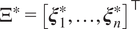 be a set of test points with corresponding outputs
$ {\mathbf{f}}^{\ast}=\tilde{f}\left({\Xi}^{\ast}\right) $
 . The GP prior implies the joint distribution

with
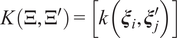
$ K\left(\Xi, {\Xi}^{\prime}\right)=\left[k\left({\boldsymbol{\xi}}_i,{\boldsymbol{\xi}}_j^{\prime}\right)\right] $
 . Denoting the vector of the kernel evaluation for a given test point
$ {\boldsymbol{\xi}}^{\ast } $
 with respect to the training points
$ {\boldsymbol{\xi}}_i $
 as
$ \mathbf{k}\left({\boldsymbol{\xi}}^{\ast}\right)={\left[k\left({\boldsymbol{\xi}}^{\ast },{\boldsymbol{\xi}}_1\right),\dots, k\left({\boldsymbol{\xi}}^{\ast },{\boldsymbol{\xi}}_n\right)\right]}^{\top } $
 , the predictions for such point are


The chosen kernel will be a radial basis function (RBF) with added white noise:

where
$ {\sigma}_f^2 $
 is the signal variance,
$ \mathrm{\ell} $
 is the correlation length scale,
$ {\sigma}_n^2 $
 is the white noise variance, and
$ {\delta}_{ij} $
 is the Kronecker delta, which is 1 if
$ i=j $
 and 0 otherwise. Other kernels are possible but do not present any apparent advantages due to the expected smoothness of the target response surface.
Training a GP regressor as a surrogate model is reduced to solving the minimization problem

where
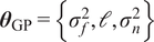
$ {\boldsymbol{\theta}}_{\mathrm{GP}}=\left\{{\sigma}_f^2,\mathrm{\ell},{\sigma}_n^2\right\} $
 denotes the set of hyperparameters of the kernel, and
$ \pi \left(\mathbf{f}|\Xi, {\boldsymbol{\theta}}_{\mathrm{GP}}\right) $
 is the probability density function of the GP evaluated at the training outputs
$ \mathbf{f} $
 , which follow a multivariate normal distribution. This corresponds to maximizing the log marginal likelihood of the training data under the GP prior. The optimization is performed using gradient-based methods, as implemented in scikit-learn’s GaussianProcessRegressor (Pedregosa et al., Reference Pedregosa, Varoquaux, Gramfort, Michel, Thirion, Grisel, Blondel, Prettenhofer, Weiss, Dubourg, Vanderplas, Passos, Cournapeau, Brucher, Perrot and Duchesnay2011), which follows the standard algorithmic framework described in Rasmussen (Reference Rasmussen2006). All models are trained using automatic hyperparameter tuning via marginal likelihood maximization with multiple restarts to avoid poor local optima.
GP constitute an appropriate surrogate modeling framework for the present application due to their sample efficiency and strong approximation capabilities for smooth, deterministic response surfaces. Their kernel-based structure enables accurate emulation of complex simulation outputs from a limited number of high-fidelity evaluations (Forrester et al., Reference Forrester, Sóbester and Keane2008). We employ GP surrogates in two distinct ways. The first approach approximates the response surfaces with respect to a set of parameters
$ \boldsymbol{\theta} \in \Theta \subset {\mathrm{\mathbb{R}}}^d $
 at a fixed set of spatial coordinates
$ X={\left\{{\mathbf{x}}_i\right\}}_{i=1}^N $
 . The second approach constructs a single GP surrogate defined jointly over both coordinates and parameters.
In the first case, the input to the GP is restricted to the parameter vector, that is,
$ \boldsymbol{\xi} =\left\{\boldsymbol{\theta} \right\} $
 . For each spatial coordinate
$ {\mathbf{x}}_i\in X $
 , a separate GP is trained and later evaluated as

using the training dataset
$ \mathcal{D}={\left\{\left({\boldsymbol{\theta}}_j,f\left({\mathbf{x}}_i,{\boldsymbol{\theta}}_j\right)\right)\right\}}_{j=1}^n $
 . Since a single simulation produces
$ N $
 observations (one per coordinate in
$ X $
 ), only
$ n $
 simulations are required to train the
$ N $
 independent GPs, one for each fixed coordinate. The surrogate can therefore interpolate only in the parameter space
$ \Theta $
 , while predictions must be evaluated at the fixed coordinate set
$ X $
 . This formulation is suitable when all quantities of interest are measured or required at predefined observation locations. This first formulation is used in the calibration of the parameters of the simulation model
$ f $
 based on experiments. In general, including a GP in the calibration process generates an additional uncertainty that should be considered in the likelihood. In some cases, it can be exploited for more efficient surrogate building (Perrin et al., Reference Perrin, Marco, Soize and Funfschilling2025). However, in the current paper we validate the GP, showing that the variances in the validation dataset can be neglected, and use it as a mean response surface.
In the second case, the GP input includes both the coordinate and parameter vectors,
$ \boldsymbol{\xi} =\left\{\mathbf{x},\boldsymbol{\theta} \right\} $
 , with
$ \boldsymbol{\xi} \in \Omega =\mathcal{X}\times \Theta \subset {\mathrm{\mathbb{R}}}^d $
 , where
$ \mathcal{X} $
 and
$ \Theta $
 denote the coordinate and parameter spaces, respectively. A single GP is trained on this joint domain, enabling predictions across both spatial coordinates and parameter values. This formulation is particularly suitable when predictions are needed on a dense or variable spatial grid, such as for computing full-field system responses. This second formulation is used for the propagation of the uncertainties in the FEM model
$ g $
 , which will be used for additional parameter identification.
3. Application to a model for tendon breakage in reinforced concrete structures
The methodology outlined in the former section 2 establishes the foundation for an uncertainty-embedded calibration. This framework is applied to a tendon-breakage experiment in pretensioned concrete instrumented with DFOS (see Section 3.1.2) on the surface, allowing the measurement of strain changes with high spatial resolution. This section provides a comprehensive description of the experimental setup and the accompanying FEM. It also presents the resulting calibration, influence, and identifiability analysis. The objective of the identifiability assessment is to analyze how accurately can we distinguish the breakage of a tendon at different depths of a concrete specimen considering measurement noise and model uncertainty.
3.1. Experimental investigation
3.1.1. Experimental setup
The experimental investigation was executed on a pretensioned concrete beam of rectangular cross section (
$ L\cdot b\cdot h=2000\cdot 300\cdot 200 $
 [mm3]). In a stressing bed, a prestress of
$ {\sigma}_{p,0}=755 $
 N/mm2 was applied to three prestressing wires with smooth surfaces (
$ {\varnothing}_p=9.4 $
 mm, St 1375/1570) and transferred to the beam after hardening of the concrete (28 d). A normal strength concrete was employed. Based on three tested cubes, a mean compressive strength of
$ {f}_{cm, cube}=55.0 $
 N/mm2 was measured. The installation of a plastic tube between the designated breakage point of the tendon and the concrete surface ensured the accessibility of the tendon after pouring of the concrete. The location was initially shifted in the
$ x $
 -direction to ensure full re-anchoring on at least one side of the breakpoint. However, DFOS measurements conducted on the tendon during the experiment showed that complete re-anchorage was attained on both sides of the breakage (Paul et al., Reference Paul, Sanio and Mark2024a). After application of the measurement equipment (details see Section 3.1.2), the beam was transferred to the test rig, which is illustrated in Figure 3a. The breakage of the centric tendon (at
$ x=800 $
 mm,
$ y=z=0 $
 , cf. Figure 3b) was then induced using a drill. The complete separation was visually confirmed through the previously installed plastic tube and terminated the experimental investigation.
Setup of the experimental investigation: specimen with drill and applied grid of distributed fiber optical sensors (a), sketch of the specimen with corresponding geometrical properties (b).

3.1.2. Instrumentation
DFOS (Speck et al., Reference Speck, Vogdt, Curbach and Petryna2019; Clauß et al., Reference Clauß, Ahrens and Mark2021) were applied to the concrete surface (Janiak et al., Reference Janiak, Becks, Camps, Classen and Hegger2023; Paul et al., Reference Paul, Sanio and Mark2024a) to instrument the test specimen. The measurement principle of DFOS can be roughly described as follows: A light beam is emitted into the sensor core (
$ \varnothing \approx 5 $
 μm; see Figure 4a), which possesses a variable refractive index along the sensor due to micro-inclusions. This variation enables identification of each measurement section through a distinctive “fingerprint.” The backscatter is converted into the frequency domain by discrete Fourier transformation. Changes in strain
$ \Delta \varepsilon $
 cause alterations in the wavelength (Samiec, Reference Samiec2011; Barrias et al., Reference Barrias, Casas and Villalba2016).
Distributed fiber-optic sensor, as used in the instrumentation of the specimen: general structure of a sensor (a), sensor grid applied to the concrete surface (b).

Figure 4. Long description
Panel a is a 3 D diagram of a D F O S cable structure. At the center is the Core with a diameter of approximately 5 mu m. The next layer outward is the Cladding with a diameter of approximately 125 mu m. The outermost layer is the yellow Coating with a diameter of approximately 155 mu m. Panel b is a photo of a concrete block. At the top is the Concrete Surface. Below this, a grid of sensors is visible. On the left, the sensors are labeled Glued D F O S, appearing as dark lines bonded to the surface. On the right, the sensors are labeled Unglued D F O S, showing the fiber looping freely across the concrete.
A variety of sensor configurations are available. The main distinction between these sensors lies in their outer sensor layer (coating, see Figure 4a), which exerts a substantial influence on the transfer of strain from the sample to the sensor. Sensors with a polyimide, acrylate, or nylon coating are popular. Rigid coatings, such as polyimide (Young’s modulus of
$ {E}_{\mathrm{Polyimide}}=400{E}_{\mathrm{Acrylate}} $
 (Chapeleau and Bassil, Reference Chapeleau and Bassil2021)), are recommended for high-precision measurements (Herbers et al., Reference Herbers, Richter, Gebauer, Classen and Marx2023). The increased risk of breakage and sensor loss exhibited by stiff coatings in the presence of cracks can be disregarded here, as the induced damage to the prestressing steel usually does not result in concrete cracks (Sträter et al., Reference Sträter, Clauß, Ahrens and Mark2024).
After the transfer of the prestressing force and removal of the formwork, the DFOS was applied to the side surfaces of the concrete structure using a two-component epoxy-based adhesive as shown in Figure 4b. The application was executed parallel and orthogonal to the tendon axis as a 2D-grid, following a meandering pattern in which a single fiber traversed varying height levels. Loops were left unglued. The outer points of each layer of the grid were distinctly designated to their respective positions on the fiber strand according to the touch-to-locate method (Konertz et al., Reference Konertz, Löschmann, Clauß and Mark2019). The interpolation of strains between measurement points and layers was achieved through bilinear interpolation (Paul et al., Reference Paul, Sanio and Mark2025). The measurements were performed throughout the entire experiment with a measuring point spacing of 2.6 mm and a frequency of 1 Hz.
3.2. Numerical model
A numerical model of the experimentally investigated specimen was developed by means of the FEM. For this purpose, the commercial software ABAQUS was used. The concrete volume was modeled with cylindrical recesses corresponding to the positions of the tendons. Both the tendon and the concrete were discretized using three-dimensional solid elements with linear shape functions. A uniform element size was used in regions remote from the tendons, while progressive mesh refinement was applied toward the prestressing steel. This approach is consistent with established FEM practices for reinforced and prestressed concrete structures (van Meirvenne et al., Reference van Meirvenne, de Corte, Boel and Taerwe2018). The analysiswas performed using a static step-wise procedure, with loads applied incrementally under quasi-static conditions. Details are provided in the upcoming subsections.
3.2.1. Constitutive laws
The nonlinear Concrete Damage Plasticity (CDP) constitutive law, developed by Lubliner et al. (Reference Lubliner, Oliver, Oller and Oñate1989) and improved by Lee and Fenves (Reference Lee and Fenves1998) was employed for the concrete. It combines isotropic, non-associative plasticity with damage parameters to consider the degradation of the material. The effective stress
$ \overline{\boldsymbol{\sigma}} $
 was calculated by means of the elasticity matrix
$ {\boldsymbol{D}}_0^{el} $
 , the total strain tensor
$ \boldsymbol{\varepsilon} $
 , and the plastic strain tensor
$ {\boldsymbol{\varepsilon}}^{\hskip.2em pl} $


For the computation of the Cauchy stress tensor
$ \boldsymbol{\sigma} $
 , the scalar degradation factor
$ \left(1-d\right) $
 was additionally employed

The computation of
$ d $
 depends on
$ \overline{\boldsymbol{\sigma}} $
 and a set of two hardening variables
$ {\tilde{\boldsymbol{\varepsilon}}}^{\hskip.2em pl} $
 . These hardening variables refer to equivalent plastic strains and are introduced to differentiate between behavior under compression (crushing failure;
$ {\tilde{\varepsilon}}_c^{\hskip.2em pl} $
 ) and tension (cracking failure;
$ {\tilde{\varepsilon}}_t^{\hskip.2em pl} $
 ). In addition to the degradation of the elastic stiffness, these also control the evolution of the yield function (Jankowiak and Lodygowski, Reference Jankowiak and Lodygowski2005)

$ \overline{\boldsymbol{\sigma}} $
 was decomposed into one invariant describing the volume change (hydrostatic stress
$ \overline{p} $
 )

and one component describing the shape change (deviatoric stress
$ \overline{\mathbf{S}} $
 )

with I as the identity tensor.
$ \overline{\boldsymbol{S}} $
 was then transformed into the invariant von Mises equivalent stress
$ \overline{q} $


The yield function
$ F $
 was expressed in terms of
$ \overline{p} $
 ,
$ \overline{q} $
 , and the Macauley Bracket
$ \left\langle x\right\rangle =0.5\left(|x|+x\right) $
 as

Its shape was defined by
$ \alpha $
 ,
$ \beta $
 , and
$ \gamma $
 , which are calculated according to


The ratio of initial equibiaxial to uniaxial compressive yield stress
$ \frac{\sigma_{b0}}{\sigma_{c0}} $
 was used to compute
$ \alpha $
 (Eq. (52)). The function
$ \beta $
 considers the effective stress
$ \overline{\boldsymbol{\sigma}} $
 computed by means of the hardening variables
$ {\tilde{\varepsilon}}_c^{\hskip.2em pl} $
 and
$ {\tilde{\varepsilon}}_t^{\hskip.2em pl} $
 (eq. (53)), while
$ \gamma $
 is derived from
$ {K}_c $
 , which represents the ratio of the second stress invariant of the tensile meridian to that of the compressive meridian (eq. (54)).
$ \frac{\sigma_{b0}}{\sigma_{c0}}=1.16 $
 and
$ {K}_c=\frac{2}{3} $
 are commonly used (van Meirvenne et al., Reference van Meirvenne, de Corte, Boel and Taerwe2018).
$ {\overline{\sigma}}_{\mathrm{m} ax} $
 denotes the maximum eigenvalue of
$ \overline{\boldsymbol{\sigma}} $
 (Jankowiak and Lodygowski, Reference Jankowiak and Lodygowski2005).
For non-associative plasticity, the plastic flow
$ {\dot{\boldsymbol{\varepsilon}}}^{\hskip.2em pl} $
 resulted from the derivative of the flow potential function

The Drucker–Prager hyperbolic function was used for this purpose. It also takes
$ \overline{p} $
 and
$ \overline{q} $
 as input parameters and is defined by the eccentricity
$ \unicode{x025B} $
 , the mean tensile strength of the concrete
$ {f}_{ctm} $
 and the dilation angle in the
$ \overline{p}-\overline{q} $
 -plane
$ \psi $
 . Commonly used values are
$ \unicode{x025B} =0.1 $
 mm and
$ \psi =30{}^{\circ} $
 (van Meirvenne et al., Reference van Meirvenne, de Corte, Boel and Taerwe2018).
The CDP distinguishes between compressive and tensile loading. For both loading paths, the formulation developed by Krätzig and Pölling (Reference Krätzig and Pölling2004) was used, employing the parameters suggested by Birtel and Mark (Reference Birtel and Mark2006). Details regarding the formulations can be derived from their work. Under uniaxial compressive stress, ductile behavior with pronounced nonlinear hardening and a softer drop in resistance was captured. As shown in Figure 5a, the first branch of the stress–strain relationship was linear-elastic
$ {\sigma}_{c(1)}\left({\varepsilon}_c\right) $
 (for
$ {\sigma}_c<0.4{f}_{cm} $
 ). The second branch
$ {\sigma}_{c(2)}\left({\varepsilon}_c\right) $
 of the stress–strain relation represented the nonlinear hardening phase (for
$ 0.4{f}_{cm}\le {\sigma}_c\le {f}_{cm} $
 ). It reflected progressive microcracking and damage accumulation in the cement matrix, accompanied by stress redistribution and aggregate interlock, which together enable a continued increase in load-carrying capacity despite a gradual reduction in stiffness (van Mier et al., Reference van Mier, Reinhard and van der Vlugt1987). The third branch described the behavior after the stress exceeded the mean compressive strength
$ {f}_{cm} $
 . It was governed by a progressive loss of load-bearing capacity due to crack formation.
Specifications of the computational model: behavior of concrete under uniaxial compression (a), behavior of concrete under uniaxial tension (b), close-up of the interface at the breakage point (c), local forces at the steel-concrete interface (d), contact specification normal to the interfaces by an exponential relationship between clearance
$ c $
 and contact pressure
$ p $
 , according to ABAQUS [Dassault Systèmes Simulia Corporation (2025)] (e).

Figure 5. Long description
The five panels are organized as follows.
Panel a. A line graph of concrete under uniaxial compression. The y-axis is stress sigma sub c and the x-axis is strain epsilon sub c. The curve starts at origin 0.0, rises linearly to 0.4 f sub cm, then curves parabolically to a peak at f sub cm corresponding to strain epsilon sub c, 1, before declining.
Panel b. Two line graphs for uniaxial tension. The left graph shows a linear increase of stress sigma sub t against strain epsilon sub t up to f sub ctm. The right graph shows an asymptotic decay of stress sigma sub t against crack opening w.
Panel c. A cross-section diagram of a steel tendon embedded in concrete. At the left Break Point, the concrete flares away from the tendon. Arrows indicate normal and shear forces acting along the interface. A force P sub 0 pulls the tendon to the right.
Panel d. A diagram of the Hoyer-Effect at the interface. It shows a force vector F decomposed into normal force N and vertical force V using angle alpha. Equations include R equals mu times V, N equals sin(alpha) times F, and the limit as alpha approaches 0, N approaches 0.
Panel e. A line graph showing an exponential pressure-overclosure relationship. The y-axis is contact pressure p and the x-axis is clearance c. The curve remains at zero for positive clearance and increases exponentially once clearance reaches c sub 0 and becomes negative, passing through p sub 0.
Under tension (Figure 5b), the model depicted brittle behavior, which occured after the mean tensile strength
$ {f}_{ctm} $
 was exceeded. Subsequently, for
$ {\sigma}_t>{f}_{ctm} $
 ,
$ {\sigma}_t $
 was calculated from the crack width
$ w $
 , which according to Hillerborg (Reference Hillerborg and Wittmann1983) was computed as
$ w={l}_e\cdot {\varepsilon}_t^{in} $
 (with the element length
$ {l}_e $
 ).
The constitutive law of the steel was linear-elastic, since the prestress applied to the tendon
$ {\sigma}_{p0} $
 in the experiments did not exceed the yield strength of St 1375/1570. The constitutive law was therefore described using only the Young’s Modulus
$ {E}_p $
 and Poisson Ratio
$ {\nu}_p $
 .
3.2.2. Contact formulation
The pretensioning of a tendon leads to a reduction in its diameter
$ {\varnothing}_p $
 . The release of the prestressing force during a tendon breakage hence results in an increase of
$ {\varnothing}_p $
 to its initial value (see Figure 5c). To appropriately model this so-called Hoyer effect (Briere et al., Reference Briere, Harries, Kasan and Hager2013), the tendon was modeled as a volume element. Contact between steel and concrete was prescribed parallel and orthogonal to the concrete–tendon interface (Figure 5d). Normal to the interface, an exponential relationship provided in ABAQUS was used. The contact pressure
$ p $
 was computed from the clearance between the interfaces
$ c $
 using an exponential function. It was defined by the clearance at which contact pressure is initiated (
$ {c}_0 $
 ) and the contact pressure
$ {p}_0 $
 when
$ c=0 $
 , as visualized in Figure 5e. The employed contact formulation allowed a realistic load transfer, while concurrently permitting slip and decoupling as a consequence of local damage.
Parallel to the interface, contact was modeled by employing Coulomb’s friction law through the friction coefficient
$ \mu $
 .
3.2.3. Simulation steps and boundary conditions
The simulation of the tendon breakage consists of three subsequent steps (cf. Table 1). The boundary conditions are set accordingly. Symmetry with respect to
$ yz $
 -plane at the breakage point (
$ x=0 $
 ) was used, and only one part of the beam (free end at
$ l=1200 $
 mm, cf. Figure 3) was modeled. In the symmetry plane (
$ x=0 $
 ), a corresponding boundary condition (
$ {u}_x={\theta}_y={\theta}_z=0 $
 ) was applied to the beam (concrete and tendons). It should be noted that solid elements do not possess rotational degrees of freedom, which reduces the symmetry conditions to
$ {u}_x=0 $
 . Vertical displacements were prohibited (
$ {u}_z=0 $
 ) through all simulation steps (1–3) at the bottom of the beam (
$ z=100 $
 mm), while displacements in
$ y $
 (
$ {u}_y $
 ) were not constrained.
Boundary conditions for different simulation steps of the computational model

Table 1. Long description
The table consists of five columns and four rows including the header.
Column headers from left to right are:
1. Simulation step.
2. Bottom surface where z equals 0.5 h.
3. Central tendon cross section where x equals 0.
4. Concrete cross section where x equals 0.
5. Tendons free end where x equals l.
Data rows:
- Initial (1): Bottom surface u sub z equals 0; Central tendon cross section u sub x equals 0; Concrete cross section u sub x equals 0; Tendons free end u sub x equals 0.
- Loading (2): Bottom surface u sub z equals 0; Central tendon cross section u sub x equals 0; Concrete cross section u sub x equals 0; Tendons free end is marked with a dash.
- Breakage (3): Bottom surface u sub z equals 0; Central tendon cross section is marked with a dash; Concrete cross section u sub x equals 0; Tendons free end is marked with a dash.
To implement the prestress to the tendons, a predefined stress field (
$ {\sigma}_{p,0}=755 $
 N/mm2) in the
$ x $
 -direction was initially applied to them. During the first simulation step (Initial), axial displacements of the tendons were prohibited at their ends (
$ x=0 $
 and
$ x=l $
 ). Then, the initial boundary conditions were altered in the two subsequent simulation steps: In step 2 (Loading), the transfer of the prestress
$ {\sigma}_{p,0} $
 from the tendons to the concretewas simulated by releasing the fixation of
$ {u}_x $
 at the free end (
$ x=l $
 ) for all tendons. In simulation step 3 (Break), the breakage was initiated by releasing the boundary condition of the central tendon at
$ x=0 $
 . The computation of the strain difference between the simulation steps, as shown in Figure 6 (right), corresponded to the measurements taken in the experiment. Table 1 summarizes the sequence of loading steps and the related boundary conditions.
Strain field determined in the direction of the tendon axis
$ \Delta {\varepsilon}_{c,x} $
 . (Left) Experimental, result from a broken tendon; (right) computational result showing strain changes between simulation steps 2 and 3.

Figure 6. Long description
The figure consists of two side-by-side heat maps. Both share identical axes: the horizontal x-axis represents distance in millimeters from 800 to 1400, and the vertical z-axis represents distance in millimeters from negative 100 to 100. A color scale to the right of each map indicates Axial Concrete Strain Change Delta epsilon sub c comma x, ranging from negative 5 in blue to 25 in dark red.
* Left Panel (Experimental): Shows an irregular distribution of strain. The left side (800 to 1000 mm) is light blue to grey, indicating low strain. Moving right, the strain increases into orange and dark red regions. A black X labeled Break Point is located at x equals 1200, z equals 0, surrounded by the highest strain concentration of approximately 20 to 25.
* Right Panel (Computational): Shows a smoother, more symmetrical gradient. The left side starts with vertical bands of blue and light blue. A large, rounded orange region of increased strain is centered around the Break Point at x equals 1200, z equals 0. The strain values in this central region are more uniform, peaking around 15 to 20, compared to the experimental result.
3.3. Experimental results
The axial strains (
$ x $
 -direction) measured on the concrete surface with DFOS after the breakage of the tendon
$ \Delta {\varepsilon}_{c,x} $
 are visualized in Figure 6 (left). The regions between the sensor strands were interpolated using bilinear interpolation (Paul et al., Reference Paul, Sanio and Mark2025). Positive strain changes of up to 25 μm/m were measured in the proximity of the breakage point (marked with a black cross). As the distance from the breakage in
$ x $
 -direction increased, strains exhibited a decreasing trend, reaching a value of 0 μm/m at approximately 350 mm. Furthermore, a slight change in the strain field was observed in the
$ z $
 -direction. The strain changes exhibited a maximum at the bottom edge (
$ z=0.5h $
 ,
$ \Delta {\varepsilon}_{c,x}\approx 25 $
 μm/m) while smaller changes were measured at the upper edge (
$ z=-0.5h $
 ,
$ \Delta {\varepsilon}_{\mathrm{c},x}\approx 18 $
 μm/m). This was attributed to the full-surface support of the specimen on its bottom surface (
$ z=100 $
 mm) during the experiment and corresponding friction.
It is important to note that the DFOS were applied after the induction of the prestressing force (after step 2), resulting in the specimen being compressed at the reference time
$ {t}_0 $
 . Due to the tendon breakage (at
$ {t}_1 $
 ), the compression diminished around the breakage point and increased again toward the free end because of the re-anchorage of the tendon in the surrounding concrete (Hegger and Bertram, Reference Hegger and Bertram2010). The measured tensile strain changes were therefore calculated as (
$ \Delta {\varepsilon}_{c,x}={\varepsilon}_{c,x}\left({t}_1\right)-{\varepsilon}_{c,x}\left({t}_0\right) $
 ).
3.4. Numerical results
Figure 6 (right) shows the strain changes coming from the simulation model presented in Section 3.2 at simulation step 3. The strain changes were computed at positions corresponding to those of the sensors on the test specimen (Section 3.1.2). To ensure better comparability with the measurements, the
$ x $
 -coordinates of the strain field were shifted to match those of the experimental investigation. Local tensile strains of up to 20 μm/m were observed around the breakage point. They decreased with increasing distance in
$ x $
 -direction. As observed in the experimentthe simulation also computed slightly greater strain changes at the bottom of the beam (
$ z=100 $
 mm; 20 μm/m) than at the top (
$ z=-100 $
 mm; 17 μm/m). This was attributed to the implementation of the boundary condition on the bottom surface (see Table 1). Overall, the calculated strain field was slightly smoother than the experimental one, as the influence of measurement noise and minor inaccuracies in sensor localization during the touch-to-locate process was mitigated. Nonetheless, correspondence between the numerical simulation and the experiment was underscored by the coefficient of determination,
$ {R}^2=0.914 $
 , and the correlation coefficient,
$ r=0.957 $
 .
3.5. Inverse problem definition
For the inverse problem, the parameters to be inferred are
$ \boldsymbol{\theta} =\left[{E}_{cm},{p}_0,{c}_0,\mu \right] $
 . All the other parameters detailed in Sections 3.1 and 3.2, required for the numerical model, were set to their default values as identified from literature or material testing (see Table 2). The geometry was set to reproduce the experimental setup described in Section 3.1.
Model parameters, descriptions, units, and default values
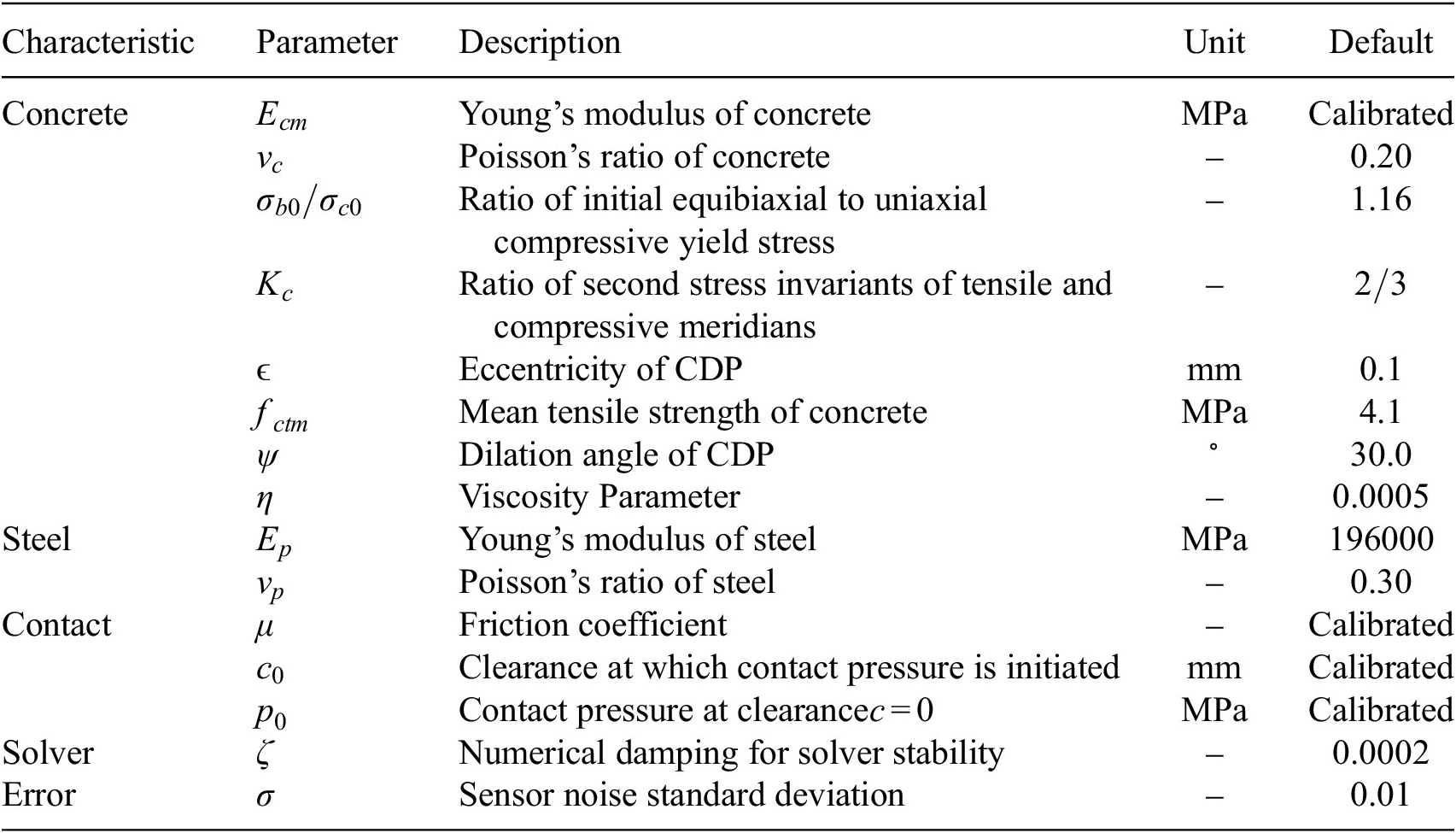
Table 2. Long description
The table consists of five columns: Characteristic, Parameter, Description, Unit, and Default.
1. Concrete characteristics:
- E sub c m: Young’s modulus of concrete, MPa, Calibrated.
- nu sub c: Poisson’s ratio of concrete, unitless, 0.20.
- sigma sub b 0 / sigma sub c 0: Ratio of initial equibiaxial to uniaxial compressive yield stress, unitless, 1.16.
- K sub c: Ratio of second stress invariants of tensile and compressive meridians, unitless, 2 / 3.
- epsilon: Eccentricity of C D P, mm, 0.1.
- f sub c t m: Mean tensile strength of concrete, MPa, 4.1.
- psi: Dilation angle of C D P, degrees, 30.0.
- eta: Viscosity Parameter, unitless, 0.0005.
2. Steel characteristics:
- E sub p: Young’s modulus of steel, MPa, 196000.
- nu sub p: Poisson’s ratio of steel, unitless, 0.30.
3. Contact characteristics:
- mu: Friction coefficient, unitless, Calibrated.
- c sub 0: Clearance at which contact pressure is initiated, mm, Calibrated.
- p sub 0: Contact pressure at clearance c = 0, MPa, Calibrated.
4. Solver characteristic:
- zeta: Numerical damping for solver stability, unitless, 0.0002.
5. Error characteristic:
- sigma: Sensor noise standard deviation, unitless, 0.01.
Note: Parameters calibrated in
$ \boldsymbol{\theta} $
 are indicated.
The observations used for the calibration were a discretization of the observations of the DFOS setup described in Section 3.1. Five rows of measurements were observed at heights
$ z\in \left\{-80,-\mathrm{40,0,40,80}\right\} $
 mm starting at the tendon breakage point toward the end of the beam (
$ x=0 $
 ) with a distance of
$ 40 $
 mm, equivalent to the vertical spacing of the DFOS. At a distance of approximately 400 mm from the break point, the measured strain changes became marginal (see Figure 6), resulting in 11 measurement points per height and accordingly 55 measurement points overall.
The predictions of the FEM model were used as output to be calibrated against. These predictions provided the difference in tensile strain
$ \Delta {\varepsilon}_{c,x} $
 before and after breakage at the DFOS location. The predictions were collected at the equivalent locations in the model as the observations. The aim was to calibrate the model parameters such that the FEM model could reliably reproduce the observations.
3.6. Gaussian Process training
The GP surrogate model was trained using four input parameters:
$ {E}_{cm} $
 ,
$ {c}_0 $
 ,
$ {p}_0 $
 , and
$ \mu $
 . These parameters were selected following a sensitivity analysis by Paul et al. (Reference Paul, Sanio and Mark2026), which demonstrated their dominant influence on the system response, while the remaining parameters exhibited negligible effects. The output quantity of interest was the difference in the strain field
$ \Delta {\varepsilon}_c $
 , extracted at
$ {N}_{\mathrm{points}} $
 spatial locations over the surface of the finite element (FEM) model corresponding to the DFOS setup. This resulted in an output vector of dimension
$ {N}_{\mathrm{points}} $
 for each simulation run.
A total of
$ {N}_{\mathrm{samples}}=100 $
 training points were generated using Latin Hypercube Sampling (LHS), ensuring good coverage of the multidimensional input space. The corresponding FEM simulations provided the training outputs. The GP was implemented with a RBF kernel combined with a white-noise kernel, using the scikit-learn framework. Inputs were normalized to the range of 0 to 1 in the space of the training samples. Outputs were normalized jointly as well to [0,1] over the whole dataset of training points. Table 3 summarizes the ranges of the input parameters and the kernel hyperparameters.
Input parameter ranges and Gaussian Process hyperparameter bounds

Table 3. Long description
The table consists of three columns: Parameter, Lower bound, and Upper bound.
* Row 1: c sub 0 in millimeters. Lower bound 0.2012. Upper bound 0.7988.
* Row 2: p sub 0 in M P a. Lower bound 2.008. Upper bound 5.992.
* Row 3: E sub c m in M P a. Lower bound 2.702 e plus 04. Upper bound 3.898 e plus 04.
* Row 4: mu (dimensionless). Lower bound 0.202. Upper bound 1.198.
* Row 5: Length scales ell sub i. Lower bound 0.01. Upper bound 100.0.
* Row 6: Signal variance sigma sub f squared. Lower bound 0.001. Upper bound 1000.0.
* Row 7: Noise variance sigma sub n squared. Lower bound 1 e minus 07. Upper bound 0.1.
The hyperparameters were optimized by maximizing the log-marginal likelihood. The noise variance
$ {\sigma}_n^2 $
 converged to the minimum admissible value (
$ {\sigma}_n^2={\sigma}_{n,\min}^2 $
 ), which reflects the high consistency between the surrogate and the training data. One GP was trained for each of the observation points, leading to different optimal hyperparameters for each case.
The predictive performance of the trained GP model was assessed using an independent validation set of
$ {N}_{\mathrm{val}} $
 samples, generated through LHS within the same parameter ranges as the training data. The FEM simulations corresponding to these validation points served as the reference values for comparison. The evaluation was based on standard regression metrics, including the coefficient of determination (
$ {R}^2 $
 ), the root mean square error (RMSE), the mean absolute error (MAE), the maximum error, the normalized RMSE (NRMSE) in percentage, and coverage statistics based on the absolute
$ Z $
 -value. The results were validated on 49 random samples on the training domain and are summarized in Table 4.
Training and validation metrics for both GP emulators

Table 4. Long description
The table consists of three columns: Metric, Train, and Validation.
* R M S E: Train 0.1627, Validation 0.4409.
* M A E: Train 0.1127, Validation 0.2738.
* R 2: Train 0.9991, Validation 0.9940.
* Max Error: Train 0.8214, Validation 1.9970.
* N R M S E (percent): Train 0.67, Validation 1.74.
* Mean absolute value of z: Train 0.6277, Validation 0.7481.
* Absolute value of z less than 2 (percent): Train 94.98, Validation 93.21.
* Absolute value of z greater than 0.5 (percent): Train 43.48, Validation 52.39.
The obtained
$ {R}^2 $
 value close to unity confirmed that the GP surrogate accurately reproduced the FEM reference outputs across the parameter space. The RMSE and MAE values were small relative to the magnitude of the strains
$ \varepsilon $
 , indicating low overall prediction error. Additionally, the predictive uncertainty estimates provided by the GP were consistent with the residuals observed in the validation set. The distribution of the normalized prediction errors remained within the
$ 95\% $
 confidence bounds for the majority of the validation points, demonstrating that the model not only achieved high accuracy but also provided reliable uncertainty quantification. These results validated the suitability of the GP surrogate for representing the input–output mapping of the FEM model in the DFOS configuration.
3.7. Parameter updating
The Bayesian calibration was carried out using the affine-invariant ensemble sampler implemented in emcee, with
$ {N}_{\mathrm{walkers}}=20 $
 walkers evolved for
$ {N}_{\mathrm{iter}}=10000 $
 iterations. The parameter space was explicitly bounded to remain within the domain of validity of the GP surrogate. In the presence of residual model–data discrepancy and strong parameter bounds, the resulting posterior could exhibit multiple disconnected modes, some corresponding to low-probability regions near the surrogate limits. In such cases, ensemble samplers could converge to distinct local probability wells (Hou et al., Reference Hou, Goodman, Hogg, Weare and Schwab2012).
To address this issue, we applied a likelihood-based clustering and pruning procedure after burn-in and at the end of sampling, designed to retain the dominant posterior mode while discarding walkers trapped in low-probability regions. The full algorithmic formulation is provided in Appendix A; here, we summarize the key principles. After burn-in, the mean log-posterior of each walker
$ i $
 was computed over the final fraction
$ \alpha $
 of its trajectory

The values
$ {\left\{{\mathrm{\ell}}_i\right\}}_{i=1}^{N_{\mathrm{walkers}}} $
 were sorted in ascending order, and clusters were identified by detecting large jumps in consecutive differences

where a jump was declared whenever

with
$ \gamma =5 $
 . These jumps partitioned the ensemble into disjoint clusters in log-posterior space. The cluster corresponding to the largest coherent posterior mass was retained, while walkers belonging to lower-probability clusters were pruned. Pruned walkers were replaced by new initial states obtained via convex combinations of retained walkers, ensuring that the ensemble remained within the high-probability region and inside the GP training domain. The corrected ensemble was then evolved for an additional
$ {N}_{\mathrm{iter}}=10000 $
 iterations. At the end of the full chain, the same clustering criterion was reapplied to obtain the final posterior ensemble, without resampling. The likelihood function was Gaussian and evaluated using the GP surrogate mean predictions and the observed DFOS data supposing a Gaussian noise variance
$ \sigma =0.01 $
 . GP hyperparameters were fixed during MCMC sampling at the optimized values obtained in Section 3.5.
Two updating approaches were considered. In the first approach, the parameter vector was defined as
$ \boldsymbol{\theta} =\left[{E}_{cm},{p}_0,{c}_0,\mu \right] $
 . In the second approach, the parameter vector was augmented with
$ {\sigma}_{E_{cm}} $
 , where
$ {E}_{cm} $
 was interpreted as the mean of a lognormal distribution and
$ {\sigma}_{E_{cm}} $
 as its standard deviation, such that
$ {\tilde{E}}_{cm}\sim \mathcal{L}\mathcal{N}\left({E}_{cm},{\sigma}_{E_{cm}}\right) $
 . The extended parameter
$ {\tilde{E}}_{cm} $
 was propagated through the GP surrogate using a PCE of degree 2, as described in Section 2.1. Table 5 presents the prior distributions and bounds for the parameters to be calibrated. The likelihood function was adapted accordingly, as shown in Equation 14. The choice of augmenting
$ {E}_{cm} $
 was motivated by its high sensitivity, as it was identified as the primary driver of variations in the model response. The uncertainty represented through
$ {\sigma}_{E_{cm}} $
 was intended to combine the effect of potential model discrepancies, regardless of their physical origin, even when these discrepancies were not directly associated with an incorrect representation of
$ {E}_{cm} $
 . The resulting uncertainty should therefore be interpreted as a vehicle for representing MFU and generating predictive distributions consistent with the observed measurements. Nevertheless, the embedded approach was inherently limited by the selected embedding parameter and the range of response variability that could be reproduced through its stochastic augmentation. In particular, when discrepancies arose from mechanisms not explicitly represented in the model and whose effects could not be approximated through variations in
$ {E}_{cm} $
 (e.g., bond–slip behavior or tendon–concrete interaction effects), part of the model discrepancy remained unaccounted for. Therefore, the transferability and effectiveness of the embedded MFU formulation depended on the ability of the chosen parameter to reproduce the dominant patterns of discrepancy observed in the response (Table 5).
Priors for parameters used in MCMC calibration

Table 5. Long description
The table consists of three columns: Parameter, Prior type, and Parameters / bounds.
* Row 1: Parameter E sub cm. Prior type is Lognormal. Parameters / bounds are mu equals 33000 M P a, sigma equals 3300 M P a, with a range of [25200, 37050].
* Row 2: Parameter sigma sub E sub cm. Prior type is Uniform. Parameters / bounds are [0.25, 7.41].
* Row 3: Parameter p sub 0. Prior type is Uniform. Parameters / bounds are [2.1, 5.7].
* Row 4: Parameter c sub 0. Prior type is Uniform. Parameters / bounds are [0.21, 0.76].
* Row 5: Parameter mu. Prior type is Uniform. Parameters / bounds are [0.21, 1.14].
The comparison between the non-embedded and embedded uncertainty calibration results is summarized in Table 6, while the calibration performance metrics are reported in Table 7. The corresponding trace and pair plots of the posterior samples are shown in Figure 7, and the predictive comparisons against the experimental observations are presented in Figure 8. Without embedding the uncertainty, the confidence intervals (CIs) were generated exclusively from the prescribed noise
$ \sigma $
 . Despite this, the resulting CIs fail to encompass the experimental observations, indicating the presence of model-form uncertainties not captured by the GP variance alone. As a consequence, the calibrated parameters weredriven toward the boundaries of their prior ranges, reflecting an artificial compensation for the missing model discrepancy. This behavior indicated that the calibration in this configuration was not physically meaningful, as reflected by the value of
$ \mu $
 tending toward its maximum allowable value and
$ {E}_{cm} $
 approaching its minimum. In this case, the predictive variance did not constitute an actual quantification of MFU in the simulation model, but rather a by-product of uncertainty in the GP surrogate, which became less accurate near the boundaries of the domain due to the sampling scheme used to generate the training dataset.
Predictive statistics (residual-based and
$ \mid Z\mid $
 -values) for the non-embedded and embedded uncertainty calibration cases

Table 6. Long description
The table is divided into two main sections of metrics: Residual-based and absolute Z-values.
Residual-based metrics include:
* Non-U Q: Mean 0.23, R M S E 1.64 (bold), Median 0.16, M A D 1.66.
* U Q: Mean 0.27 (bold), R M S E 1.67, Median 0.11 (bold), M A D 1.35 (bold).
Absolute Z-values metrics include:
* Non-U Q: Mean 1.87, Standard deviation 1.49, Median 1.52, M A D 1.22, absolute Z greater than 2 is 40 percent, absolute Z less than 0.5 is 16 percent (bold), and 95 percent Coverage is 60.
* U Q: Mean 0.94 (bold), Standard deviation 0.79 (bold), Median 0.61 (bold), M A D 0.68 (bold), absolute Z greater than 2 is 13 percent (bold), absolute Z less than 0.5 is 42 percent, and 95 percent Coverage is 87 (bold).
Bolded values indicate the best performance in each category.
Note: Best values in bold.
Comparison of posterior summaries acros calibrations with and without embedding

Table 7. Long description
The table consists of five columns: Parameter, Mean (std) and 95% C I for ‘Without embedding’, and Mean (std) and 95% C I for ‘With embedding’.
* E sub c m: Without embedding Mean 28368.30 (18.35), C I [28350.47, 28417.44]. With embedding Mean 31244.27 (894.13), C I [29336.98, 32803.68].
* sigma sub E sub c m: Without embedding values are null. With embedding Mean 3548.81 (416.91), C I [2581.66, 4216.89].
* p sub 0: Without embedding Mean 3.36 (0.03), C I [3.30, 3.43]. With embedding Mean 3.77 (0.73), C I [2.56, 5.37].
* c sub 0: Without embedding Mean 0.65 (0.01), C I [0.63, 0.67]. With embedding Mean 0.50 (0.15), C I [0.23, 0.75].
* mu: Without embedding Mean 1.14 (0.00), C I [1.14, 1.14]. With embedding Mean 0.87 (0.15), C I [0.58, 1.12].
Comparison with and without embedding of MCMC calibration for the parameters
$ {E}_{\mathrm{cm}} $
 ,
$ {\sigma}_{E_{cm}} $
 ,
$ {p}_0 $
 ,
$ {c}_0 $
 , and
$ \mu $
 . The left subfigure shows trace plots, and the right shows parameter pair plots.

Figure 7. Long description
The left panel, titled Overlay Trace Plot, contains two columns of five rows. The left column shows probability density functions and the right column shows time-series trace plots for parameters E sub cm, sigma E sub cm, c sub 0, p sub 0, and mu. Red lines represent calibration without embedding, showing narrow, static distributions. Blue lines represent calibration with embedding, showing broader, fluctuating distributions indicating higher variance and exploration of the parameter space.
The right panel, titled Overlay Pair Plot, is a triangular matrix of plots. The diagonal shows the univariate probability density functions for each parameter. The off-diagonal plots show bivariate contour plots representing the correlation between parameter pairs.
* E sub cm: The top-left diagonal plot shows a sharp red peak at approximately 28500 and a broad blue peak centered near 31500.
* sigma E sub cm: The second diagonal plot shows a blue peak near 3500.
* c sub 0: The third diagonal plot shows a sharp red spike near 0.65 and a broad blue distribution.
* p sub 0: The fourth diagonal plot shows a red spike near 3.5 and a broad blue distribution.
* mu: The bottom-right diagonal plot shows a red spike at 1.1 and a broad blue distribution peaking near 0.9.
In the bivariate contour plots, the blue regions show varying degrees of correlation, such as a strong negative correlation between p sub 0 and mu, while the red data points remain highly localized and constrained.
Predicted confidence intervals at
$ 95\% $
 of the posterior predictive for
$ \hat{\tilde{\boldsymbol{\theta}}} $
 with and without embedding. The confidence interval in the calibrated model without embedding depends only on the prescribed noise
$ \sigma $
 .

Figure 8. Long description
The x-axis is labeled Data point and ranges from 0 to 55. The y-axis is labeled Delta epsilon sub c comma m in micrometers per meter and ranges from 5 to 20. A legend at the bottom identifies five data series. Red circles represent Calibration without Embedding mean. Red dashed lines represent Calibration without Embedding plus or minus 2 sigma. Blue squares represent Calibration with Embedding mean. Blue dotted lines represent Calibration with Embedding plus or minus 2 sigma. Black X marks represent Experimental data.
The data is organized into five distinct downward-sloping clusters.
1. Data points 0 to 10. Both models closely follow the experimental data. The red dashed confidence interval is narrow and centered on the mean.
2. Data points 11 to 21. Experimental data points are slightly lower than the model means. The blue dotted confidence interval is significantly wider than the red dashed interval.
3. Data points 22 to 32. Experimental data aligns well with the mean predictions. The blue dotted interval remains wide while the red dashed interval remains tight around the mean.
4. Data points 33 to 43. Experimental data shows higher variance, with several points above the model means. The blue dotted interval encompasses these outliers, whereas the red dashed interval does not.
5. Data points 44 to 54. Similar to the fourth cluster, experimental data points are scattered above the mean. The blue dotted interval successfully captures these points.
A text box in the top left corner lists R M S E values. Calibration without Embedding is 1.636 and Calibration with Embedding is 1.675.
When the uncertainty was embedded through the stochastic representation of
$ {E}_{cm} $
 , the inferred variance was directly associated with the material stiffness. This embedding inflated the CIs and improved their coverage of the observational data. The posterior distributions of the parameters were observed to be less concentrated, as a result of the flatter likelihood induced by the inclusion of variance in the quantification. Nevertheless, these posteriors converged toward more reasonable values than the extreme estimates obtained in the model without embedding. In particular, the inferred Young’s modulus of approximately 31000 MPa, with an associated uncertainty of 3500 MPa, lay within the expected range of experimentally observed values. Additionally, a general lack of influence of
$ d $
 , together with a clear correlation between
$ {p}_0 $
 and
$ \mu $
 , was observed in the posterior behavior. The
$ Z $
 -values, defined as the normalized residuals between observations and model predictions, confirmed these findings. They showed a clear increase in coverage (87% with versus 60% without embedding) and a decrease in outliers (13% of absolute
$ Z $
 -values exceeding 2 with versus 40% without embedding), despite an increase in the percentage of the dataset for which the discrepancy was smaller than the predictive intervals (42% with versus 16% non-without embedding). Nevertheless, some observations still fell outside the 95% predictive intervals, indicating that part of the MFU remains unaccounted for, even after embedding. Moreover, the predicted variance wasvsignificantly larger than the observed residual in more than one third of the predictions, suggesting a general overestimation of the predictive uncertainty due to the remaining discrepancies.
To further investigate the remaining discrepancies observed in the predictions, an influence analysis was performed on the model calibrated with embedded uncertainty. The predictions, representing the change in normal strains after breaking the tendon on the DFOS, still did not fully cover the experimental observations. Since the sensor data originated from five different DFOS located at distinct vertical positions
$ z $
 , the observations were grouped by their distance to the tendon break, forming subsets
$ {S}_i $
 . Each subset
$ {S}_i $
 thus represented measurements obtained at a similar structural region with respect to the failure point.
The influence of each subset
$ {S}_i $
 on the posterior distribution of the parameters was quantified using
$ \phi $
 -divergences, specifically the reverse Kullback–Leibler (KL) divergence between the posterior obtained using all observations for calibration and only a subset of them (see Section 2.2). This approach allowed assessing of how the removal of each subset affected the posterior, thereby identifying which experimental groups exerted the largest influence on the calibrated model. The resulting influence metrics are illustrated in Figure 9. The top plots display the global influence
$ {\hat{D}}_{\phi}\left({S}_i\right) $
 for each subset on the full posterior, while the lower panels show, respectively, the marginal influences
$ {\hat{D}}_{\phi}^{(j)}\left({S}_i\right) $
 and
$ {\hat{D}}_{\phi}^{(j),\left(\mathrm{fix}\right)}\left({S}_i\right) $
 for each parameter
$ {\theta}^{(j)} $
 , obtained using two alternative regularization approaches. All influence values were normalized to sum to one within each case, enabling direct comparison between subsets and parameter-wise influences.
Influence analysis on the model calibrated with embedded parameters. At the top for both sides,
$ {\hat{D}}_{\phi}\left({S}_i\right) $
 for the full posterior for each
$ {S}_i $
 . On the left, influence
$ {\hat{D}}_{\phi}^{(j)}\left({S}_i\right) $
 of each
$ {S}_i $
 on the marginal posterior of the parameters
$ {\theta}^{(j)} $
 using KDE smoothing. On the right, influence
$ {\hat{D}}_{\phi}^{(j),\left(\mathrm{fix}\right)}\left({S}_i\right) $
 of each
$ {S}_i $
 on the marginal posterior of the parameters
$ {\theta}^{(j)} $
 fixing the means of the other parameters. Influence values have been normalized to add to 1 in their respective case to enable the direct comparison.

Figure 9. Long description
A vertical color bar on the far right indicates phi influence D sub phi values from 0.00 in dark blue to 0.30 in dark red. Both heatmaps share a common X axis labeled Subdivision Position with indices 0 through 10 and a common Y axis with rows labeled Global, E sub c m, sigma sub E c m, c sub 0, mu, and p sub 0.
* The left panel titled Kernel approach shows a Global row with values ranging from 0.022 to 0.213. The highest influence is in the E sub c m row at position 0 with a value of 0.331. Other notable peaks include mu at position 9 with 0.225 and c sub 0 at position 5 with 0.199.
* The right panel titled Fixed Mean approach shows an identical Global row. In the parameter rows, the highest influence values are shifted. E sub c m peaks at position 0 with 0.283. Sigma sub E c m shows a significant peak at position 10 with 0.364. The parameters mu and p sub 0 show a trend of increasing influence from left to right, peaking at position 10 with values of 0.230 and 0.217 respectively.
The global influence analysis revealed a dominant contribution from the first subset, corresponding to the portion of the DFOS located closest to the tendon break. This region coincided with the observations least well captured by the predictive intervals, confirming that the local response near the failure point drove the largest posterior changes. A secondary effect was also observed in the sixth to seventh subdivision, affected by the increased discrepancies in the first set of observations (data points 7 and, to a lesser extent, 6).
The marginal influence analyses highlighted that the parameter
$ {E}_{cm} $
 was primarily driven by observations located close to the tendon breaking point. These measurements corresponded to the region exhibiting the largest model–data discrepancies and the highest sensitivity to calibration, indicating that variations in
$ {E}_{cm} $
 induced the most significant changes in the predicted strain response in this zone. The embedded variance parameter
$ {\sigma}_{E_{cm}} $
 was also strongly affected in the fixed-point influence analysis, suggesting that part of the local discrepancy was being absorbed through an increased variability of the embedded stiffness rather than through systematic shifts in the mean response. A similar, albeit weaker, effect was observed for the last observation, which also displayed residual discrepancy at the identified optimum.
Two complementary influence formulations were considered to disentangle these effects. In the kernel-based influence analysis, the parameters were marginalized, such that the influence measure reflected the sensitivity of the joint posterior distribution after integrating out parameter dependencies. In this formulation, part of the discrepancy attributed to a given parameter could be compensated by correlated variations in other parameters, leading to a more spatially homogeneous influence pattern for
$ {\sigma}_{E_{cm}} $
 . In contrast, the fixed-mean influence analysis evaluated sensitivity by conditioning on fixed values of all parameters except the one under investigation. This isolates the direct contribution of individual parameters to the posterior change and was therefore more sensitive to localized discrepancies that could not be alleviated through compensating parameter interactions.
The KDE-based analysis provided a global view of how observations influenced the inferred uncertainty when all parameter interactions were accounted for, while the fixed-mean analysis reveals which parameters were directly responsible for reconciling local discrepancies in the predictions. The latter was particularly relevant in the context of parameter transfer, where mean values are typically propagated to simulations of real structures. Taken together, the two influence measures indicated that the observed discrepancies near the breakage region stem from a localized model deficiency, which was partially absorbed through increased embedded stiffness variability when parameter interactions were allowed.
3.8. Identifiability assessment of parameters of interest
The final step of the analysis aimed to assess the identifiability of parameters of interest when the calibrated and uncertainty-embedded model was transferred to a full-scale, realistic structure. The parameters inferred from the calibration with uncertainty quantification, specifically the stochastic Young’s modulus
$ {\tilde{E}}_{cm} $
 , were propagated to a new FE model representing a structural component with a different cross-section, based on the dimensions of a real bridge. This transfer enabled the propagation of both epistemic and aleatory uncertainties obtained from the experimental calibration into a context that more closely resembled a real engineering application.
The motivation for this analysis arose from the intended use of the model in SHM of prestressed concrete bridges. In a realistic setting, the calibrated parameters from laboratory-scale experiments would be employed to interpret field measurements, with the objective of diagnosing potential failures in the prestressing tendons. In particular, if a tendon breaks, the resulting strain field on the concrete surface changed in a way that depended on the depth of the breakage
$ a $
 (Paul et al., Reference Paul, Sanio and Mark2024b). Identifying which tendon had failed therefore corresponded to solving an inverse problem: given a new set of observed strains, determine the value of
$ a $
 (i.e., the depth of the broken tendon) that most likely produced them. Such identification was only feasible if the predictive distributions corresponding to different tendon depths were sufficiently distinct. The separability analysis presented here thus evaluated whether the embedded model uncertainty allowed discrimination between potential tendon breakage depths.
To perform this assessment, the stochastic Young’s modulus
$ {\tilde{E}}_{cm} $
 , characterized by its mean and variance from the calibration, was treated as a random variable and propagated through the FE model for each tendon depth
$ a $
 . This yields predictive distributions of the strain response
$ \varepsilon \sim {\mathcal{G}}_{\mathbf{x}}(a) $
 at spatial points
$ \mathbf{x} $
 , quantifying how uncertainty in material and bond parameters translated into uncertainty in the observable strain field.
The upscaled structural model represented a symmetric T-shaped beam of length
$ l $
 , shown in Figure 10. Its cross-section was defined by the web height
$ {h}_w=1000 $
 mm, web width
$ {t}_w=1200 $
 mm, flange thickness
$ {t}_f=250 $
 mm, and flange width
$ {b}_f=2250 $
 mm. The geometric parameters remain constant for all analyses. Since the study focused on the breakage of a single tendon and the concrete remained uncracked, the intact tendons were not explicitly modeled. The position of the tendon within the cross-section was defined by
$ \left(\Delta y,\Delta z\right) $
 , where
$ \Delta y $
 denoted the embedding depth with respect to the evaluated concrete surface and corresponded to the control parameter
$ a $
 . The strain response was evaluated along the outer surface of the web at
$ y=0.5{t}_w $
 .
Computational model of an upscaled T-beam used to investigate the separability of predictions for different tendon depths.

The central question of this study was whether the propagated uncertainty from the calibrated parameters still permitted distinguishable predictions for different values of
$ a $
 . If the predictive distributions for different tendon depths overlapped significantly, then new observations would not allow reliable inference of which tendon had failed. Conversely, well-separated predictive distributions implied that the distributed surficial strain measurement could be effectively used to identify the failure location. Hence, the separability of the predictive strain distributions provided a quantitative measure of the model’s diagnostic capability and defined a metric for the informativeness of potential sensor locations.
Direct evaluation of the FE model for all
$ a $
 values and sensor points would be computationally prohibitive. To overcome this limitation, the propagation of
$ {\tilde{E}}_{cm} $
 was performed using a PCE of degree 2, yielding the mean
$ {\tilde{\mathbf{m}}}_{\mathrm{PCE}} $
 and standard deviation
$ {\tilde{\boldsymbol{\sigma}}}_{\mathrm{PCE}} $
 fields at each spatial point. Two GP surrogate models were trained to emulate the PCE outputs: one for the mean field and one for the standard deviation. Each GP takes as input
$ \left(\mathbf{x},a\right) $
 and outputs either
$ {\tilde{\mathbf{m}}}_{\mathrm{PCE}} $
 or
$ {\tilde{\boldsymbol{\sigma}}}_{\mathrm{PCE}} $
 . Both employed an isotropic Matern kernel with a white-noise component, with inputs and outputs scaled to [0,1]. The optimized hyperparameters of the GP surrogates are listed in Table 8. The input dataset was composed of
$ x $
 ,
$ z $
 and
$ a $
 in a grid
$ \left[5\times 15\times 10\right] $
 divisions, from which 2500 data points were taken randomly for training the GPs and the remaining 5000 were used for validation. Validation metrics are presented in Table 9.
Hyperparameter summary for mean and std GP surrogates (input parameter
$ a $
 )

Table 8. Long description
The table consists of four columns: Hyperparameter, Bounds, Mean G P, and Std G P. It contains three rows of data.
* Row 1: Hyperparameter ell. Bounds are open bracket 0.01, 100.0 close bracket. Mean G P is 0.5561. Std G P is 0.2561.
* Row 2: Hyperparameter sigma sub f super 2. Bounds are open bracket 0.001, 10000.0 close bracket. Mean G P is 780.3. Std G P is 0.6031.
* Row 3: Hyperparameter sigma sub n super 2. Bounds are open bracket 1 e minus 08, 0.01 close bracket. Mean G P is 1.373 e minus 05. Std G P is 7.549 e minus 05.
Validation metrics for GP mean and std emulators

Table 9. Long description
The table consists of three columns: Metric, Mean G P, and Std G P.
* R M S E: Mean G P is 0.1639, Std G P is 0.0282.
* M A E: Mean G P is 0.05257, Std G P is 0.00938.
* R 2: Mean G P is 0.9978, Std G P is 0.9938.
* Max Error: Mean G P is 3.772, Std G P is 0.4837.
* N R M S E (percent): Mean G P is 0.23, Std G P is 0.45.
* Mean absolute value of z: Mean G P is 0.3125, Std G P is 0.2445.
* Absolute value of z less than 2 (percent): Mean G P is 97.70, Std G P is 97.51.
* Absolute value of z greater than 0.5 (percent): Mean G P is 13.09, Std G P is 10.19.
The separability of the predictive distributions associated with different tendon depths
$ a $
 was quantified using the GP surrogates following Algorithm 1. Two complementary statistics were employed. The first is a Min-
$ \Delta $
 metric, which measures the smallest distinguishable difference in tendon depth
$ \Delta a $
 such that the corresponding predictive distributions at a given sensor location remained separable under the propagated uncertainty. Smaller values of
$ \Delta a $
 indicated higher sensitivity of the sensor to changes in
$ a $
 . The second is a PDF-overlap metric, which quantifies the degree of overlap between predictive probability density functions associated with different values of
$ a $
 ; low overlap implies high discriminative power, while high overlap indicates limited ability to distinguish tendon breakage depths.
The optimization required to compute these statistics was performed using the Nelder–Mead method. The resulting spatial fields of separability and overlap are shown in Figure 11. The top-left panel presented a classification of virtual sensor locations in the
$ x $
 -
$ z $
 plane on the concrete surface (
$ y={t}_w/2 $
 ) into separable (
$ \circ $
 ) and non-separable (
$ \times $
 ) regions based on the combined criteria of the two metrics. The middle-left panel showed the spatial distribution of the maximin
$ \Delta a $
 values obtained with the Min-
$ \Delta $
 method, highlighting regions where small changes in tendon depth could be reliably distinguished. The bottom-left panel reported the value
$ {a}^{\ast } $
 at which
$ \Delta a $
 is maximized, indicating which tendon depth was most influential at each sensor location. The top-right panel displayed the minimum PDF overlap across all considered tendon depths, identifying sensor locations that provide the strongest discrimination. The middle-right panel showed the maximum overlap, revealing regions where predictive distributions remained highly overlapping regardless of
$ a $
 . The bottom-right panel summarized the range of PDF overlap, providing a measure of variability in discriminative power across depth scenarios.
Comparison of sensor separability and overlap metrics for two classification approaches. Each subplot shows the spatial distribution of virtual sensors in the
$ x $
 –
$ z $
 plane, with separable sensors (
$ \circ $
 ) identified by the Min-
$ \Delta $
 method and non-separable sensors (
$ \times $
 ) identified by the PDF-overlap method. The position of the tendon breakage is at
$ x=0 $
 mm and
$ z=600 $
 mm. (Top left) Sensor separability classification map. (Middle left) Maximin
$ \Delta a $
 field (Min-
$ \Delta $
 method). (Bottom left)
$ {a}^{\ast } $
 field indicating the tendon depth where
$ \Delta {a}^{\ast } $
 is maximal. (Top right) Minimum PDF overlap field. (Middle right) Maximum PDF overlap field (Overlap method). (Bottom right) Range of PDF overlap summarizing overlap variability. Interpolation between applicable sensors is performed using cubic splines.

Figure 11. Long description
The figure consists of six panels arranged in two columns and three rows. All panels share an X Position axis from 0 to 3000 millimeters and a Z Position axis from 400 to 800 millimeters.
Top Left: Sensor Separability Classification. A scatter plot showing green circles for separable sensors using the Min-Delta method and red crosses for non-separable sensors using the Overlap method. Separable sensors are concentrated at the far left and center-right, while non-separable sensors appear in clusters around X equals 750 and X greater than 2250.
Middle Left: Maximin Delta a field. A contour plot with a color scale from 0.0000 to 0.1350. High values (yellow) are concentrated between X equals 1000 and 2000, while low values (dark blue) are at the left edge.
Bottom Left: a super star field. A heatmap with a color scale from 0.00 to 0.90. It shows a complex distribution of values where Delta a super star is maximal, with high values (yellow) appearing in the right half of the active sensor region.
Top Right: Min P D F Overlap. A heatmap with a color scale from 0.00 to 0.90. The field is predominantly light blue (low overlap) for X greater than 500, with a small white region at the top center.
Middle Right: Max P D F Overlap. A heatmap with a color scale from 0.00 to 0.90. Most of the field for X greater than 500 is orange to yellow, indicating high maximum overlap, with a white void in the bottom center.
Bottom Right: Range of P D F Overlap. A heatmap showing the difference between Max and Min overlap. Dark blue regions (low range) dominate the right side, while yellow and white regions (high range) are concentrated between X equals 500 and 1500.
The results of the separability analysis revealed four distinct regions along the beam that corresponded to different identifiability regimes. Close to the breakage point (
$ x<450 $
 mm), the predictive distributions for different tendon depths
$ a $
 were well separated, indicating that the model response was highly sensitive to the breakage position and that the propagated material-form uncertainty did not obscure this sensitivity. In this region, the strain response was dominated by the local stress redistribution caused by the tendon break, which led to measurable and distinguishable strain patterns across different tendon depths.
Moving away from the breakage zone, a region of poor separability was observed (450 mm
$ <x<900 $
 mm). Here, the predictive distributions corresponding to different
$ a $
 values exhibited significant overlap. This behavior was attributed to the interaction between the geometric eccentricity of the broken tendon, which induces a bending moment around the vertical axis
$ z $
 in the structure, and the uncertainty embedded in the stochastic Young’s modulus
$ {\tilde{E}}_{cm} $
 . The superposition of these two effects generated similar strain patterns for different tendon depths, thereby reducing the discriminatory power of the model in this intermediate region.
Further along the beam (900 mm
$ <x<1900 $
 mm), the separability increased again, as the bending-induced strains stabilized and the relative effect of the tendon position on the overall strain field becomes more distinct. However, this trend does not persist indefinitely: far from the breakage point (
$ x>1900 $
 mm), the strain changes become too small to be distinguishable within the propagated uncertainty, and the predictive distributions once again overlapped. This spatial pattern confirmed that the propagation of the material-form uncertainty through the calibration framework provided valuable diagnostic information. It identifies regions where predictions were robust and distinguishable, and conversely, where model predictions should not be trusted for inverse inference. Consequently, this information could directly guide sensor placement strategies in practice, ensuring that measurements were taken in regions of maximal separability when the number of available sensors was limited. This assessment was specific to the calibrated model, a different setup would generate other predictive distributions and affect separability.
It should be noted that the present separability assessment was conducted on a single point-sensor basis, evaluating each spatial location independently. Considering multiple sensor locations simultaneously or a DFOS, and accounting for their spatial correlation, would enable a more comprehensive and tighter assessment of separability, potentially improving the identification of the breakage depth. This extension was left for future work. Additionally, the possible error introduced by transferring the calibrated parameters from the experimental setup to the upscaled model was not been explicitly quantified, as such transfer errors were inherently model-dependent and could not be rigorously evaluated within the current framework.
4. Conclusions
This work presented a comprehensive, uncertainty-aware workflow for tendon breakage localization in prestressed concrete members, integrating laboratory-scale tendon breakage experiments and DFOS measurements, high-fidelity FEM, surrogate modeling via GPs, and Bayesian inference with embedded MFU. The framework addressed the fundamental challenge that direct calibration on real structures is infeasible, as destructive tendon-breakage tests can hardly be performed in situ. By first calibrating models under controlled laboratory conditions and embedding uncertainties probabilistically, the workflow enabled transferable, trustworthy predictions of tendon breakage locations and depths in realistic structural configurations such as bridges.
The starting point of the workflow was a detailed FEM representation of the tendon-breakage experiment, capable of reproducing the nonlinear structural response from re-anchoring and strain redistribution following a tendon breakage. To enable efficient probabilistic calibration, the computationally intensive FEM simulations were replaced by GP surrogate models that emulated the structural response across the parameter space while retaining accuracy in the regions most informed by the data. This surrogation step provided the foundation for the subsequent Bayesian calibration, in which the parameters governing material and bond behavior were inferred using the MCMC sampler. A key achievement of this study lay in the explicit quantification of model form uncertainty through parameter embedding. By interpreting the effective Young’s modulus
$ {E}_{cm} $
 as a stochastic variable with an inferred variance
$ {\sigma}_{E_{cm}} $
 , the calibration gained the ability to represent structural and modeling discrepancies probabilistically. This embedding not only improved the statistical consistency between model predictions and observations but also provided a physically interpretable mechanism for uncertainty propagation, thereby increasing the reliability and trustworthiness of the inferred parameters. Building upon the calibrated model, an influence analysis based on
$ \phi $
 -divergence (using Kullback–Leibler divergence) was conducted to quantify the impact of specific data subsets on the posterior distributions. This diagnostic step allowed the identification of regions and parameters most responsible for model discrepancy, most notably, the sensitivity of the posterior to measurements near the tendon breakage. The insights gained from this analysis could directly guide the improvements to the model, targeting the area around the tendon break.
The final stage of the workflow demonstrated the transferability and predictive power of the calibrated and uncertainty-embedded model. By propagating the stochastic parameters to a realistic structural configuration, the study assessed the identifiability of an additional parameter, for example, the depth of a broken tendon, through a separability analysis of the propagated predictive distributions. This analysis confirmed that the embedded MFU preserved sufficient separability near the breakage point to enable tendon-depth identification, while also revealing spatial regions where predictions are unreliable due to overlapping uncertainties. These findings provided a rational basis for optimizing sensor placement and for assessing confidence in inverse identification tasks. In summary, the developed framework achieves a seamless integration of experimental evidence, physics-based simulation, surrogate modeling, and probabilistic reasoning. The resulting methodology formed a comprehensive, data-informed approach for uncertainty-aware model calibration and validation in structural applications, and established a foundation for extending such techniques to large-scale engineering systems.
Although the proposed workflow demonstrated a reliable integration of experimental data, surrogate modeling, and Bayesian uncertainty embedding, several limitations must be acknowledged. The calibration strongly depended on the quality and representativeness of the experimental DFOS measurements, which were specific to the laboratory setup. Consequently, the inferred posterior distributions and embedded uncertainty reflected the conditions and boundary effects of that configuration. When transferring the parameters to different geometries or scales, these dependencies might not be fully preserved, introducing unquantifiable epistemic uncertainty. The use of GP surrogates and the embedding of MFU through a single stochastic variable
$ {\tilde{E}}_{cm} $
 constituted additional simplifications. While these approaches enabled efficient calibration and propagation, they assumed that the main discrepancies can be captured by the variability in the effective stiffness, neglecting spatial or multi-parameter sources of model error. Similarly, both the influence and separability analyses were performed under independence assumptions, that is, considering each sensor or subset separately, thus not fully capturing correlations that could enhance discriminative power. These limitations highlighted that, although the framework provided a systematic and trustworthy foundation for uncertainty-aware model calibration and interpretation, future developments should aim at multi-source uncertainty representation, adaptive surrogate refinement, and joint sensor analysis to further improve generalization and reliability.
Future developments of the proposed framework will focus on extending its capability to capture more complex and realistic sources of uncertainty and to enhance its diagnostic resolution. Incorporating correlations between sensor measurements and spatially distributed observations (Mu et al., Reference Mu, Liang, Shen and Zhang2022) will enable multivariate separability and influence analyses, providing tighter and more reliable identification of parameter changes. Adaptive surrogate modeling strategies (Semler and Weiser, Reference Semler and Weiser2023), such as active learning or multi-fidelity GP, could be employed to refine the representation of highly nonlinear responses while maintaining computational efficiency. Moreover, the extension of the embedding concept to multiple MFU parameters, potentially coupled with spatial variability fields, would allow a more physically consistent quantification of discrepancies (Strong et al., Reference Strong, Oakley, Brennan and Breeze2015). Finally, integrating experimental design optimization into the workflow could guide sensor placement and data acquisition strategies, maximizing the information gain for future structural monitoring or model updating campaigns (de Souza Mello et al., Reference de Souza Mello, Pereira and Gomes2024; Orozco et al., Reference Orozco, Chamoin, Cortial, de Buhan and Soulier2025; Zhang et al., Reference Zhang, Chun and Lin2025; Bakeer et al., Reference Bakeer, Herbers and Marx2025). In this context, the separability analysis presented in this study could provide a quantitative basis for sensor layout design. Rather than relying exclusively on deterministic sensitivity metrics, sensor placement strategies could prioritize locations that maximize the separability of potential damage states while accounting for both model and measurement uncertainties. Such an approach may lead to more robust monitoring systems and more reliable damage localization in operational bridge environments, where uncertainty levels are typically higher than those encountered under laboratory conditions. Uncertainty from the effect of unknown loads and environmental conditions could enter as additional stochastic terms in the forward model evaluated for the separability assessment, allowing for a seamless integration of those more complex scenarios. Additionally, the current formulation is most directly applicable to the optimization of the placement of individual sensors. Extending the framework to multisensor systems, particularly distributed sensing technologies such as DFOS, would require explicitly accounting for the covariance structure among measurements. In such cases, separability should be evaluated based on the joint response of the sensor network, as correlations between measurements can significantly influence both identifiability and damage-localization performance.
Data availability statement
Replication data and code can be found at Zenodo: https://doi.org/10.5281/zenodo.18713387.
Acknowledgments
The authors used ChatGPT to assist with drafting of this article, specially to improve text clarity and grammar. GPT-4 and GPT-5 were accessed from https://chatgpt.com/ and used without modification between July 2025 and February 2026. All scientific content, ideas, and interpretations originated from the authors. Claude Sonnet 4.5 was used through the Github Copilot interface for assisted programming in generating the code required to obtain the results. All the content was thoroughly reviewed by the authors.
Author contribution
Conceptualization: M.W., D.S., P.M., J.F.U.; Data curation: D.A.A., A.P.; Data visualization: D.A.A., A.P.; Formal analysis: D.A.A., A.P.; Funding acquisition: M.W., D.S., P.M., J.F.U.; Investigation: D.A.A., A.P.; Methodology: D.A.A., A.P.; Project administration: M.W., D.S., P.M., J.F.U.; Resources: P.M., J.F.U.; Review and editing: M.W., D.S., P.M., J.F.U.; Software: D.A.A., A.P.; Supervision: M.W., D.S., P.M., J.F.U.; Writing original draft: D.A.A., A.P.. All authors approved the final submitted draft.
Funding statement
This research was supported by the German Research Foundation (DFG) - Project number 461030501 in the special focus program SPP 2388/1 “Hundert plus – Verlängerung der Lebensdauer komplexer Baustrukturen durch intelligente Digitalisierung” (Hundred Plus – Extending the service life of complex building structures through intelligent digitalization) in the subprojects B04: Pattern detection of internal prestressing wire breaks on concrete surfaces (project number 501774158) and C07: Data driven model adaptation for identification of digital twins of bridges (project number 501811638).
Competing interest
The authors declare none.
Ethical standards
The research meets all ethical guidelines, including adherence to the legal requirements of the study country.
A. Clustering and pruning of walker ensembles
After the burn-in phase of an ensemble MCMC sampler and at thee end of the full chain, we performed a postprocessing step that clustered walkers according to their average log-posterior values and pruned walkers belonging to low-probability clusters. The objective was to suppress walkers stuck in local minima in probability wells while preserving the largest coherent mode of the posterior. Our implementation followed Hou et al. (Reference Hou, Goodman, Hogg, Weare and Schwab2012), with some modifications to consider potential multiple low-probability clusters and to increase robustness against outliers.
Let the ensemble contain
$ N $
 walkers and let
$ {\left\{\ln {\pi}_{i,t}\right\}}_{t=1}^T $
 denote the log-posterior distribution of walker
$ i $
 during the last
$ T=\lfloor \alpha \hskip0.1em {T}_{\mathrm{burn}}\rfloor $
 steps of burn-in, where
$ \alpha \in \left(0,1\right) $
 is a user-specified fraction, which in this paper will be 0.2. Define the mean terminal log-posterior

Sort these values in ascending order
$ {\mathrm{\ell}}_{(1)}\le {\mathrm{\ell}}_{(2)}\le \dots \le {\mathrm{\ell}}_{(N)} $
 , and denote the associated permutation of walker indices by
$ \sigma $
 . Define the first-order differences

and the median difference
$ \tilde{d}=\mathrm{Median}{\left\{{d}_k\right\}}_{k=1}^{N-1} $
 . A jump was declared wherever

where
$ \gamma >0 $
 is a user-specified jump factor that we will choose as 5.0.
Let
$ J=\left\{{k}_1,{k}_2,\dots, {k}_M\right\} $
 be the ordered list of detected jump locations. These induce
$ M+1 $
 disjoint clusters

For each cluster
$ {C}_m $
 with
$ m=1,\dots, M+1 $
 , define its size
$ {S}_m=\mid {C}_m\mid $
 . We select the largest cluster index as

and define the acceptance threshold
$ {\mathrm{\ell}}_{\mathrm{thr}}={\mathrm{\ell}}_{\left(\min {C}_{m^{\star }}\right)} $
 . All walkers satisfying
$ {\mathrm{\ell}}_i\ge {\mathrm{\ell}}_{\mathrm{thr}} $
 were retained. Let
$ K $
 be the set of retained indices and
$ P $
 its complement.
For the next MCMC phase, let
$ {\mathbf{x}}_i^{\mathrm{last}} $
 denote the last state of walker
$ i $
 during burn-in. Construct an array
$ {\mathbf{X}}^{\mathrm{new}}\in {\mathrm{\mathbb{R}}}^{N\times d} $
 , where
$ d $
 is the parameter dimension, by

Resampling of pruned walkers was performed by convex mixing of two randomly drawn kept walkers

where
$ a,b\in K $
 are drawn without replacement and
$ w\sim \mathrm{Uniform}\left(0,1\right) $
 . This preserves the support of the dominant cluster while replenishing the ensemble with diversified points lying within the high-probability region.
At the end of the full chain, the same clustering formulation was reapplied to the final ensemble. In this second application, pruning was performed without resampling; we simply returned the subset of walkers satisfying
$ {\mathrm{\ell}}_i\ge {\mathrm{\ell}}_{\mathrm{thr}} $
 as the final reduced posterior ensemble.
B. Stable estimation of
$ {\boldsymbol{D}}_{\boldsymbol{\phi}}\left(\boldsymbol{S}\right) $
measures from posterior samples

B.1. Estimation of global influence
Given a posterior sample
$ {\left\{{\boldsymbol{\theta}}^{(i)}\right\}}_{i=1}^N\sim \pi \left(\boldsymbol{\theta} |Y\right) $
 , we can estimate
$ {D}_{\phi }(S) $
 from Equation 25 empirically as

To prevent numerical underflow or overflow in evaluating likelihoods and ratios, all computations were performed in log-space. Let

Define
$ M=\underset{i}{\max }-{\mathrm{\ell}}_i $
 to stabilize exponentiation, and the scaled weights

Then, the log-space equivalent of the first term in
$ {D}_{\phi }(S) $
 was written using the log-sum-exp operation as

Similarly, the second term was obtained as the sample mean of
$ {\mathrm{\ell}}_i $
 as

Finally, combining both terms gives the numerically stable estimator

This log-space formulation ensured stable and accurate computation of
$ {D}_{\phi }(S) $
 even when the likelihood ratios
$ {\pi}_S\left(\boldsymbol{\theta} \right) $
 span several orders of magnitude, a situation typical in high-dimensional or data-intensive Bayesian models.
B.2. Estimation of marginal influence with KDE approach
Analogously, we approximate the two expectations of Equation 28 by empirical averages using posterior samples
$ {\left\{{\theta}_j^{(i)}\right\}}_{i=1}^N $
 as

Because
$ {w}_i={\pi}_S\left({\boldsymbol{\theta}}^{(i)}\right) $
 may be very small or large, we compute the kernel weights in log-space as well for numerical stability. Let
$ {\mathrm{\ell}}_i=\log {\pi}_S\left({\boldsymbol{\theta}}^{(i)}\right) $
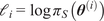 ,
$ M=\underset{i}{\max }-{\mathrm{\ell}}_i $
 , and set scaled weights
$ {\tilde{w}}_i=\exp \left(-{\mathrm{\ell}}_i-M\right) $
 . Then

and the corresponding log-smoothed value is

B.3. Estimation of marginal influence with Fixed Mean approach
The marginal influence of Equation 31 was analogously approximated by samples
$ {\theta}_j^{(i)} $
 as

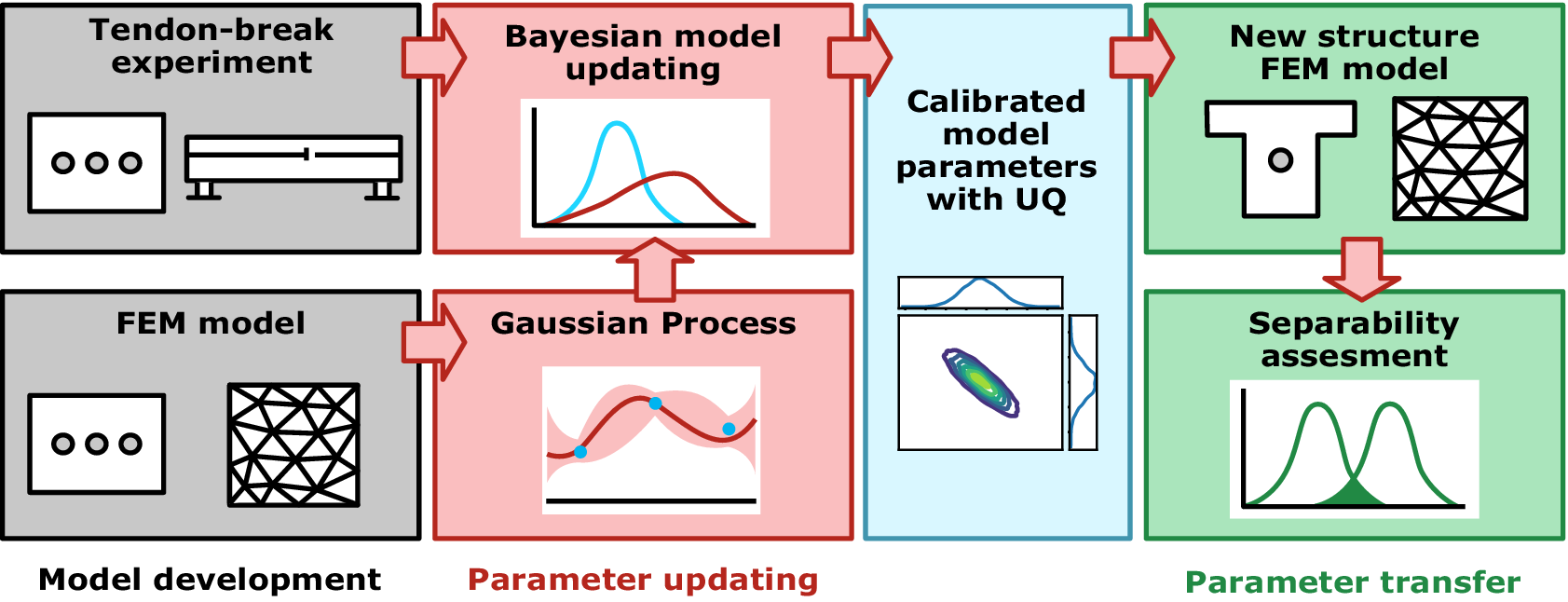
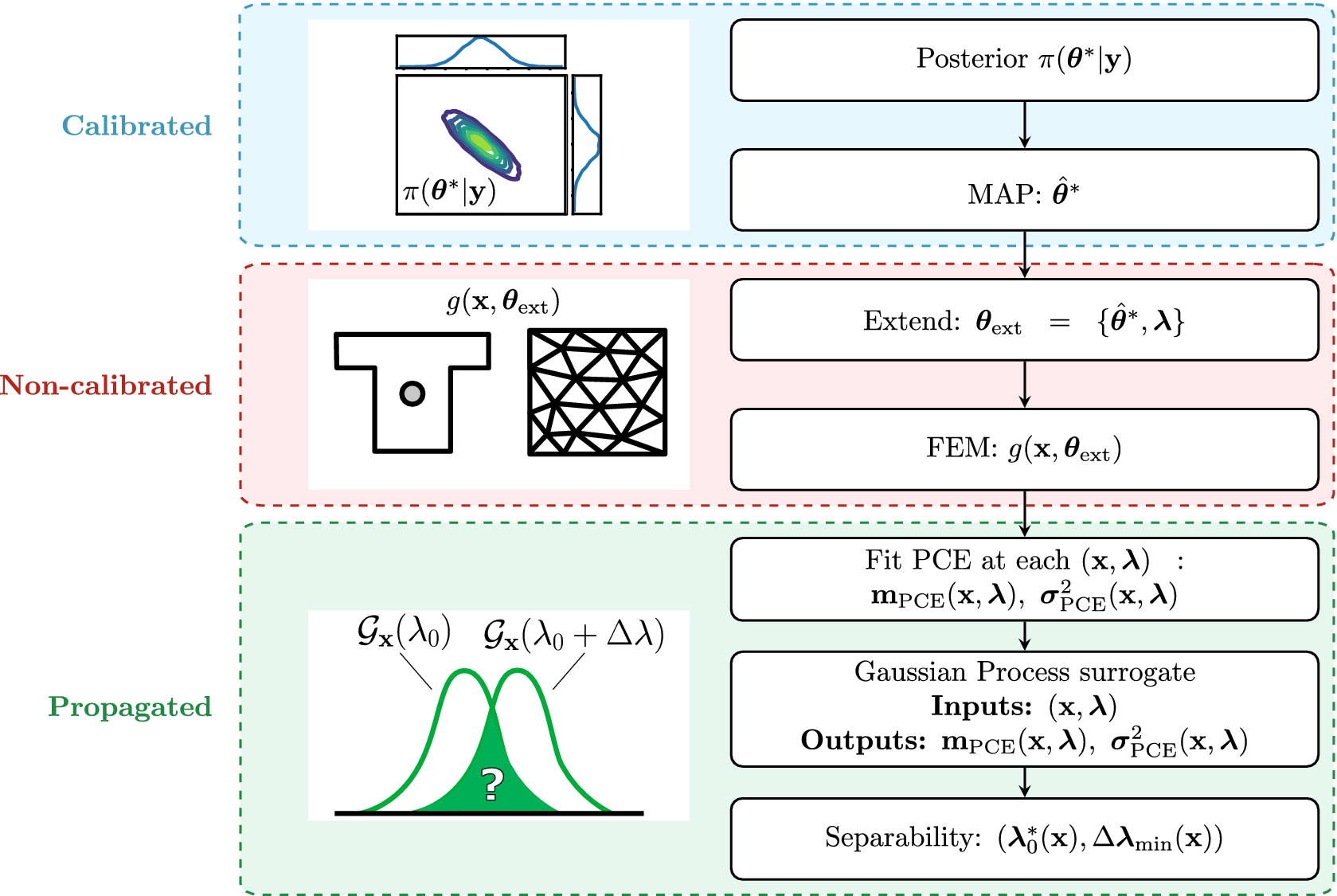


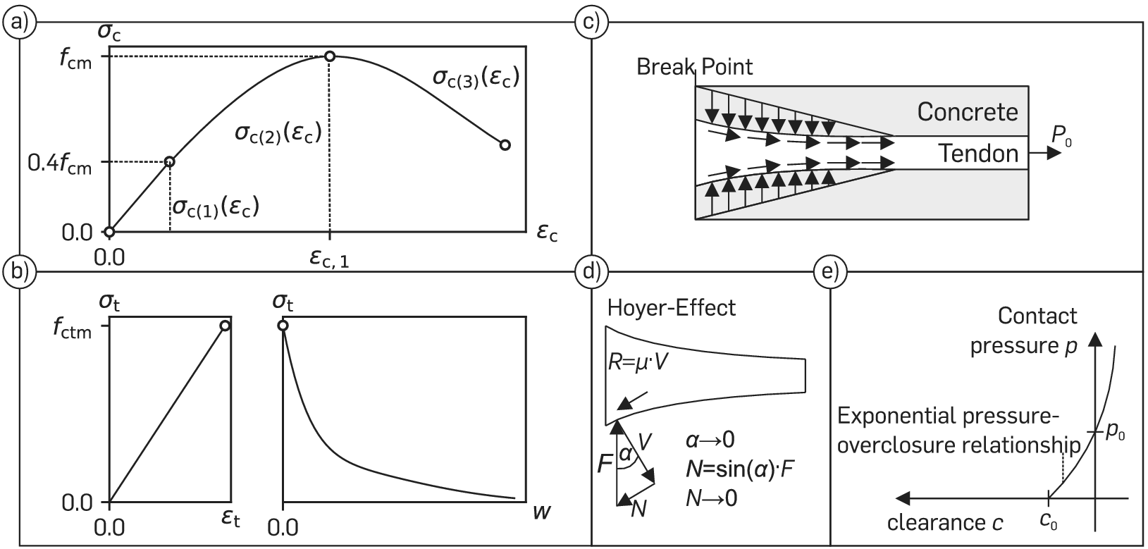



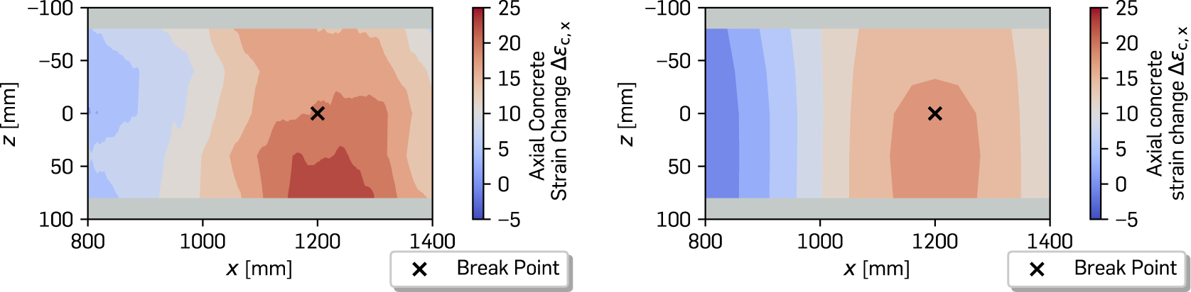


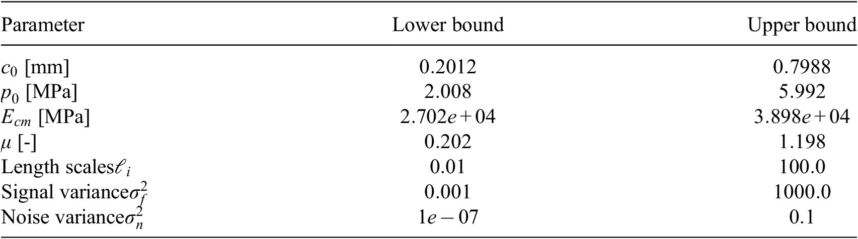
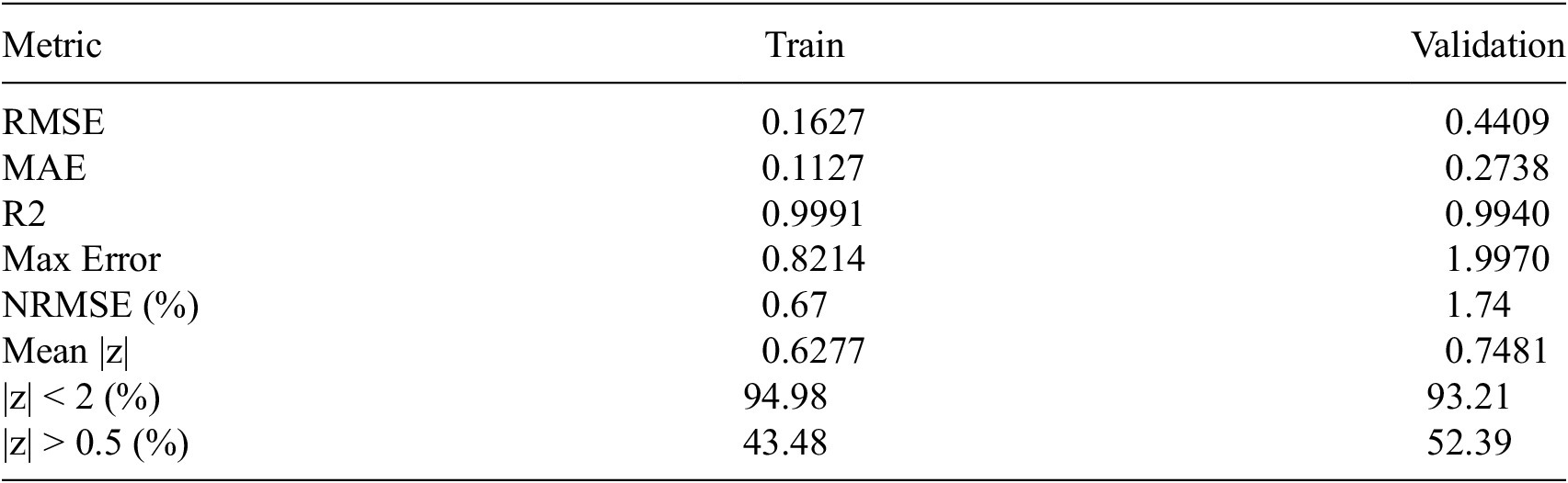
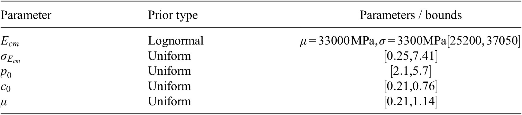
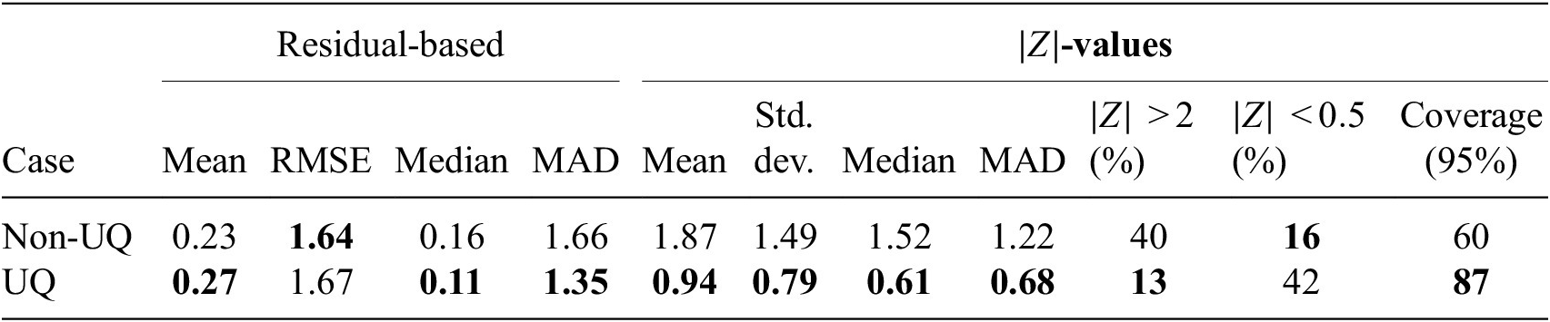

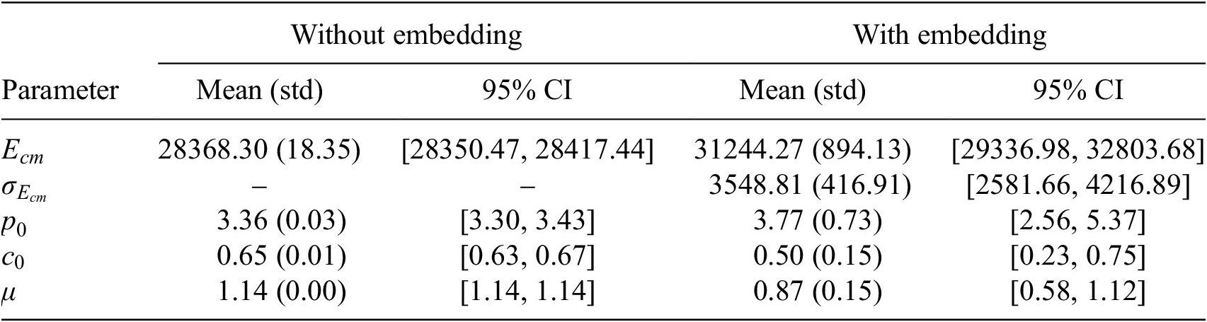


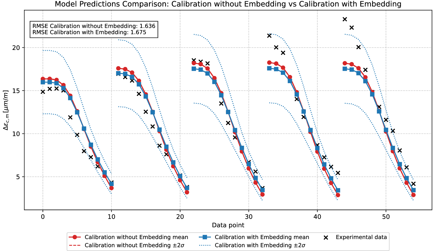


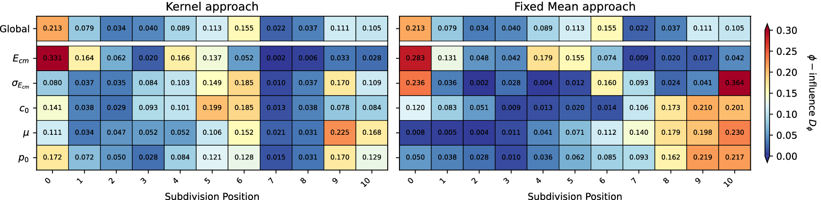




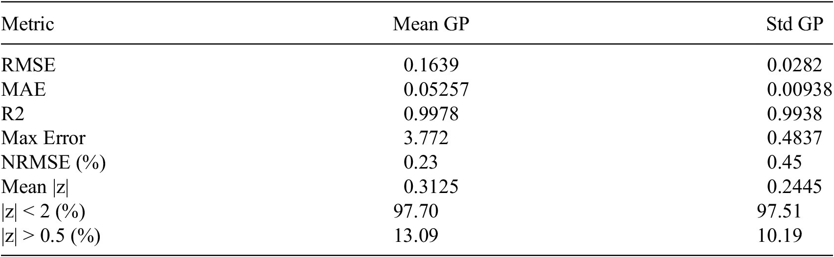


 Open access


Comments
No Comments have been published for this article.