

1 Introduction
The initial phases in a real planning application project typically consist of requirements gathering and preliminary modeling during which the structure and characteristics of the problem are gradually transformed into a formal model that can be sent to an artificial intelligence (AI) planner. We view the overall design process as a series of phases each requiring different knowledge representations for different purposes: languages for gathering requirements, languages to enable formal reasoning to analyze model consistency or dynamics, input languages for planning systems, etc. From this perspective, translations among different knowledge representations are inherent to the design process and the choice of representation languages for the early phases is crucial. Knowledge Engineering (KE) and Requirements Engineering (RE) concepts have been investigated (McCluskey, Reference McCluskey2002; McCluskey & Simpson, Reference McCluskey and Simpson2004; Vaquero et al., Reference Vaquero, Romero, Tonidandel and Silva2007) to support this choice of the representation set as well as to guide the overall design process for planning applications. However, few tools and languages have been applied to the initial design phases.
The itSIMPLE project (Vaquero et al., Reference Vaquero, Romero, Tonidandel and Silva2007) is a research effort to develop a reliable KE environment to support the design of planning applications. Unlike other tools, itSIMPLE focuses on the initial phases of a disciplined design cycle. As a consequence, an important feature of the system is the support for an informal or semi-formal process of requirements elicitation and the transition of requirements to formal specifications. Requirements are gathered and modeled using Unified Modeling Language (UML; Object Management Group (OMG), 2005), a general purpose language broadly accepted in software engineering and RE. UML is used to specify, visualize, modify, construct and document domains or artifacts, generally following an object-oriented approach. We adopt the Naked Object (NO) approach (Pawson & Mathews, Reference Pawson and Mathews2002)—a decoupling and encapsulating discipline—as a guide to requirements elicitation and knowledge modeling. A second representation, Petri Nets (PN; Reisig, Reference Reisig1985; Murata, Reference Murata1989), is automatically generated and used to analyze dynamic aspects of the requirements captured by UML models. A third representation, Planning Domain Description Language (PDDL; Gerevini & Long, Reference Gerevini and Long2006), is also automatically generated in order to input the planning domain and instance to an automated plannerFootnote 1. PDDL is a widely used input language within the AI planning research community; however, it is not intuitive for non-planning experts or domain specialists for problem formulation. itSIMPLE, therefore, translates the entire model described in UML to a solver-ready PDDL representation. Plans from different planners can then be simulated and evaluated using validation tools. itSIMPLE's framework and translators reduces the gap between real planning applications, which are seldom represented directly in PDDL and state-of-the-art AI planners.
itSIMPLE has been applied to several real planning applications since 2005, including petroleum supply port management (Sette et al., Reference Sette, Vaquero, Park and Silva2008), project management (Udo et al., Reference Udo, Vaquero, Silva and Tonidandel2008), manufacturing (Vaquero et al., Reference Vaquero, Tonidandel, Barros and Silva2006), information systems, and intelligent logistics systems. These case studies represent a sample of different applications, including some of reasonable size and complexity.
In this paper, we present the design process supported by itSIMPLE and its language framework. The main contributions of this work are:
• An integrated design environment for AI planning applications that supports a project process consisting of requirements gathering, modeling, analysis, and validation phases that interleave and complement each other.
• A minimal language framework that fits the overall project process. This framework includes a UML core representation and the translation processes to the PN formalism for analysis and to a solver-ready PDDL model for plan generation.
The rest of this paper is organized as follows. First, we give an overview of the itSIMPLE project and the design environment provided by the tool. Next, we describe the language framework and translation processes that guide the user from requirements gathering in UML to PN-based analysis, and to a PDDL model. We then include a brief description of some practical results and related work. Finally, we present the future work and conclusion.
2 The itSIMPLE design environment
The project development process supported by itSIMPLE is divided into three primary phases, which may be re-entered multiple times in an iterative fashion:
1. Requirements elicitation: An informal or semi-formal process is used to generate the requirements for and restrictions on a planning application. The representation used in this phase is UML. It is important that a strong discipline is adopted to guide this phase. itSIMPLE supports object-oriented requirements elicitation based on NOs (Pawson & Mathews, Reference Pawson and Mathews2002).
2. Domain analysis: Once there is no further change in the set of requirements, called saturation (Sommerville & Sawyer, Reference Sommerville and Sawyer1997), the project transitions to static and dynamic analysis of the domain. itSIMPLE can perform static analysis directly in the UML representation while using Elementary PN (Rozemberg & Engelfriet, Reference Rozemberg and Engelfriet1998) for dynamic analysis.
3. Plan generation and analysis: Finally, the analyzed domain is transformed to a PDDL representation suitable for input to planners. Various planners can be used to generate plans leading to an evaluation of plan correctness and planner efficiency. Problems or opportunities in either of these areas typically lead to transitions back to further requirements elicitation and/or domain analysis.
Thus, the overall process proposed is based on a minimal set of formal and semi-formal representations in UML, PN, and PDDL that suits real applications with a minimal amount of information as required by the Axiomatic Design approach (Suh, Reference Suh2001).
A completely formal design process is not possible since it starts, by definition, with non-formalized, and perhaps tacit, knowledge. Such is the usual case with systems that support requirements elicitation and engineering. The formal specification of translations between the different representations is the target of the current work and of the current implementation of itSIMPLE. We return to this point in the next section after providing more details on the above phases and the re-entrant nature of the design process.
2.1 Requirements elicitation and modeling with Unified Modeling Language
Any planning system is embedded in a real environment, that is, a myriad of ‘non-system’ tools, objects, people, and processes with which it must interact. It is necessary to have a detailed model of this domain environment and it is important that this model be developed independently of the planning system (McDermott, Reference McDermott1981). In itSIMPLE, the modeling phase is composed of dual layered sections: one concerned with the modeling of the environment where the plan is to be executed and the other dealing with a specific planning instance to be solved. For example, in the well-known logistics domain the goal is the delivery of a set of packages from specific locations to a set of destinations using a set of trucks. The environment role is played by the city map, composed by streets (two-way and one-way), blockages, dead ends, bridges, and the locations of gas stations. The problem instance is defined by the location and destinations of the packages and trucks.
In itSIMPLE, requirements and knowledge are gathered and modeled in an object-oriented fashion using a suite of UML diagrams: class, state machine, timing, and object diagrams. Such object-oriented approach is guided by the NO (Pawson & Mathews, Reference Pawson and Mathews2002) principle of encapsulation: while modeling, designers focus on identifying the domain objects and ensure that all the system logic is captured by methods on such objects. Thus, an object in the model should not just be a collection of data about the real artifact; it should encapsulate all the behavior that we need to apply to the object. NO is an approach commonly used in software development for faster development and greater agility.
The UML diagrams are used to represent the main aspects of the domain objects in the domain environment and in the planning problem as follows:
• Static information: Objects and agents, along with their properties, relationships, and constraints are defined by using class diagrams. The elements in the class diagram represent most of the static characteristics of a domain. In the logistics example, trucks, locations, packages, and streets are some of the classes that can have properties and relationships.
• Dynamic information: The dynamics are encoded in the domain objects through their operators (methods). Operators and their parameters are also represented using class diagrams, however, their dynamics need a more elaborate representation, such as state machines. Although class diagrams provide operator names and parameters, state machines provide the logical behavior of actions in each class. A state machine diagram represents the possible states of an object and how actions affect it. Thus, a state machine diagram is built for each class that has dynamic features. In order to specify pre- and post-conditions of actions, itSIMPLE uses a formal constraint language derived from UML, called Object Constraint Language (OCL; OMG, 2003). OCL is a pure specification language commonly used for invariants on classes and types to describe pre- and post-conditions on operations and methods, to specify constraints on operations, and to specify derivation rules for attributes for any expression over a UML model. OCL is not commonly available in other UML tools, but in itSIMPLE it is essential for specifying action conditions.
To better address real-world problems, itSIMPLE represents time-based planning domains using timing diagrams (OMG, 2005). Such diagrams cover dependencies that could be expressed by parameters—such as timelines that denote the time spent to perform an action. Currently, time slices are allowed in timing diagrams to define durative-actions. Enlarging the use of itSIMPLE to include more temporal problems (e.g., scheduling) requires a dense time representation. This development is planned for future work.
• Problem definition: Planning problem instances are modeled by using object diagrams representing snapshots of a planning domain. The most common snapshots are the initial state and the goal state. Users can create preferences and constraints (e.g., on the plan trajectory) using object diagrams as well, capturing either desirable or undesirable situations (Vaquero et al., Reference Vaquero, Romero, Tonidandel and Silva2007). When the user creates a state, an object diagram checker verifies whether the objects and their relationships respect the rules defined in the class diagrams. For example, it checks in real time if a particular object can be associated with another, given the set of multiplicity and other constraints. The object diagram checker helps the designer to create valid states according to the classes’ definition.
2.2 Domain analysis and validation
The domain analysis phase is based on static information analysis and validation of dynamics using a state-transition approach. Static analysis is performed by creating snapshots and possible scenarios (using object diagrams) based on the class diagrams and all constraints defined on them.
Dynamic analysis is performed using PN as recently recommended by OMG. In the current version of itSIMPLE, only Elementary PN (Rozemberg & Engelfriet, Reference Rozemberg and Engelfriet1998) is used as a sound and generic schema that includes state machines as a special case. Validation is based on simulation or a token player, in a secured elementary net that is used primarily for qualitative analysis. Further, structural analysis will be included as well as more complex analysis based on High-Level and Object-oriented Nets.
2.3 Plan generation
After modeling and analyzing the domain, a natural step is to generate and examine plans by using AI planners. As an integrated environment, itSIMPLE uses PDDL to communicate with solvers, including Metric-FF, FF, SGPlan, MIPS-xxl, LPG-TD, LPG, hspsp, SATPlan, Plan-A, Blackbox, MaxPlan, LPRPG, and Marvin. This feature gives itSIMPLE a significant flexibility to exploit recent advances in solver technology. Indeed, a designer can test different planning approaches with their model and identify the most promising solver. Moreover, new planners can be easily attached to itSIMPLE.
With such variety of planners, a pre-selection process becomes necessary as it is impractical to run all planners on all problem instances. itSIMPLE provides an initial selection of planners by matching domain requirements (e.g., durative-action, fluents, constraints) and planners’ supporting requirements. Designers can run these planners and obtain the resulting plans to be analyzed, all in the same environment. All available planners can be run for a given set of problems and reports and charts are presented to users showing a comparison of their performance.
2.4 Plan analysis and model refinement
Even with a very disciplined design process, imprecisions and small inconsistencies can result in unexpected behavior from solvers. Such problems could be caused by incompatibility between the solver and the specific problem or because of an incorrect model. In the latter case, plan analysis can reveal unexpected behavior that raises potential inconsistencies in specification.
In one of the features of itSIMPLE for plan analysis, a plan visualization and simulation is provided by a functionality called ‘Movie Maker’ (Vaquero et al., Reference Vaquero, Romero, Tonidandel and Silva2007). This functionality captures the model of a domain and the plan specification in PDDL and shows the simulation of interactions between the plan and the domain through a sequence of object diagrams, snapshot-by-snapshot, while highlighting every change caused by an action. Designers are able to insert new actions during simulation to check different situations. This plan analysis tool can help users to adjust models by observing plans being executed.
Another important functionality is to be able do evaluate plans according metrics defined by the user. In itSIMPLE, a static resource manger was included for plan analysis called ‘Variable Tracking’. Resources such as battery power level, fuel usage, tank level, and on/off states can be evaluated in charts represented in itSIMPLE's GUI (Vaquero et al., Reference Vaquero, Romero, Tonidandel and Silva2007). Moreover, the user can specify metrics and criteria that determine the quality for a plan (e.g., the value of domain variables, action counters, or linear expressions). Using these metrics, it is possible to evaluate the plan according to user's preferences. Such preferences could be refined during the design process.
3 The language framework and translation processes
The language framework of itSIMPLE was designed to be flexible and open, allowing different languages to be added. In order to integrate the languages and phases noted above, the environment uses Extensible Markup Language (XML; Bray et al., Reference Bray, Paoli, Sperberg-McQueen, Maler and Yergeau2004) as a core meta-language. XML is widely used in data transaction systems, web applications, data sharing systems, and ontologies. A significant advantage of using XML is that most of the representational languages integrated into itSIMPLE have a direct representation in XML: Petri Nets Markup Language (PNML; Billington et al., Reference Billington, Christensen, van Hee, Kindler, Kummer, Petrucci, Post, Stehno and Weber2003) for PN and eXtensible Planning Domain Definition Language (XPDDL; Gough, Reference Gough2004) for PDDL.
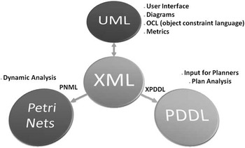
All UML diagrams and expressions are stored directly in an XML representation. All internal verifications and translations are performed using the core XML representation, as shown in Figure 1. The adjustments to and maintenance of the model resulting from analysis of different representations are currently performed manually in the UML/XML representation.
The architecture of the integrated languages. UML = Unified Modeling Language; XML = Extensible Markup Language; PDDL = Planning Domain Definition Language

In order to transform information from one language to another, itSIMPLE uses specially designed translators based on mapping processes. Depending on which translation is requested by users, the tool extracts the necessary data from the central XML-based representation. In this paper, we focus on the translation process between UML/XML and PDDL providing only a brief description of the UML/XML to PN mapping.
3.1 From Unified Modeling Language/Extensible Markup Language to Petri Nets
The mapping from UML/XML to PN captures data from state machine diagrams. A PNML representation is created from the state machine, and is graphically presented to the user as PN for visualization and simulation. In the current version, we use Elementary PN to check for bottlenecks and deadlock situations.
PNML fits properly in itSIMPLE's analysis process via the concept of modules (encapsulations of behavior) in an extension called modular PNML (Kindler & Weber, Reference Kindler and Weber2001). Modules are similar to object-oriented concepts in UML and NOs. A module in PNML encapsulates a set of places and transitions that define the behavior of an object or artifact. A PN of the entire UML model can be created by instantiating and combining modules in PNML. For more details on the mapping process implemented in itSIMPLE3.0, see Vaquero et al. (Reference Vaquero, Silva, Ferreira, Tonidandel and Beck2009b).
3.2 From Unified Modeling Language/Extensible Markup Language to PDDL
UML models do not have a formal semantics, leading to the possibility of unintended interpretations of a given model as well as different choices in defining a translation from UML to a formal language. In order to create a suitable translation from UML to PDDL (with semantics based on STRIPS (Lifschitz, Reference Lifschitz1987) and first order logic (FOL)), we must define an interpretation for UML models. In this section, we describe the interpretation of UML as a PDDL model implemented in itSIMPLE3.0 based on the elements found in PDDL. We use XPDDL for our implementation of the PDDL representation.
Because PDDL models are divided into two files, domain and planning instance, we present the mapping process of each individually. This presentation assumes the reader is familiar with the syntax and meaning of PDDL.
3.2.1 Domain translation
A PDDL domain file contains static information about the model and the specification of actions/operators. This information is found in class diagrams, state machine diagrams, and timing diagrams in the UML/XML representation. The following procedure is used for generating a PDDL domain model.
1 UMLtoPDDLdomain (xmlmodel)
2 Map types;
3 Map predicates and functions;
4 Map actions;
5 Map temporal characteristics of actions;
6 Map constraints;
7 return PDDLdomain;
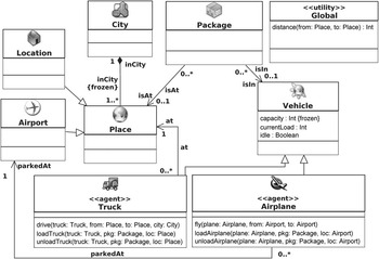
Figure 2 illustrates the class diagram from a logistics domain that will be used as our running example.
A UML class diagram of the logistics domain. UML = Unified Modeling Language

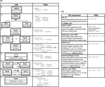
Mapping types: The mapping process starts from class diagrams, from which all defined classes are extracted and represented in the :types section of the domain file. The hierarchy relationship is preserved as, in PDDL, when a type A is declared to be of type T (A − T), it means that A is a subset of type T. The same meaning can be extracted from classes and dependencies in UML. When a class Cl is a specialization of another class Cl′, it means that Cl is a subset of Cl′. For example, the class Truck is connected to Vehicle class by a specialization in Figure 2, providing the same relationship as Truck-Vehicle in PDDL. Figure 3a (rows 1 and 2) shows the mapping definition.
(a) Mapping PDDL types, predicates and functions from UML class diagrams; (b) Mapping OCL expression to PDDL conditions. PDDL = Planning Domain Definition Language; UML = Unified Modeling Language; OCL = Object Constraint Language

Mapping predicates and functions: Predicates and functions are also mapped to PDDL from UML class diagrams, specifically from class attributes and associations. Boolean attributes are represented as predicates in the :predicates section of PDDL. For mapping Boolean attributes in UML to predicates in PDDL, we consider the following definition:
Definition 1: Boolean attributes. Given a class Cl in a UML class diagram, a Boolean attribute attr defined as an attribute of Cl is translated to PDDL as a unary predicate in the form (attr ?obj-Cl).
The semantics of a predicate in PDDL follows the semantics of a predicate in FOL. For example, the FOL sentence,  $$\[--><$> \exists x\:\;\:truck(x) \wedge idle(x) <$><!--$$, is true if and only if x is a truck and x is free. The semantics can be extracted from UML: a class Truck and its Boolean attribute idle means that object or variable of type Truck can be free. In PDDL, the example would be mapped as a predicate in the form (idle ?x-Truck).
Integer and float attributes are represented as fluents in :functions of PDDL following the same approach as Boolean attributes. Integer attributes such as capacity and currentLoad (see Figure 2) are examples of mapped fluents in PDDL. The following definition is used for mapping numeric attributes.
Definition 2: Integer and Float attributes. Given a class Cl in a UML class diagram, a numeric (integer or float) attribute attr defined as an attribute of Cl is translated to PDDL as a unary fluent in the form (attr ?obj-Cl).
Some attributes are treated differently depending on the target version of PDDL. For example, attributes that are instances of another class (e.g., attribute onTable of a Block class is of type Table) are mapped as predicates or functions depending on the PDDL version (row 5 of Figure 3a). In versions before 3.1, these attributes are represented as predicates, for instance (onTable ?x-Block ?y-Table). In version 3.1, these cases are naturally mapped as fluents in :functions, for example (onTable ?x-Block)-Table.
Definition 3: Non-primitive attributes. Given the classes Cl1 and Cl2 in a UML class diagram, an attribute attr defined as an attribute of Cl1 and with the type defined as Cl2 is translated to PDDL as a binary predicate in the form (attr ?obj1-Cl1 ?obj2-Cl2) for version before 3.1. For PDDL version 3.1 and newer, the attribute is translated as a unary fluent in the form (attr ?obj1-Cl1)-Cl2.
Parametrized attributes are also used in UML class diagrams. For example, an Integer attribute distance(from:Place, to:Place) from a class Global is a possible parametrized attribute in a class diagram. In such cases, the representation depends on the attribute's type as described above. In the distance example, it would be represented in the :functions section of PDDL as (distance ?from-City ?to-City).
UML has an extensibility mechanism, called stereotypes which allow new model elements to be derived from existing ones. The utility stereotype is commonly used to represent global characteristics of a model. The attributes of a class with stereotype utility are mapped to PDDL functions or predicates, depending on the their types and omitting the parameter representing the owner of the attributes.
An association in UML connects two classes and has a role-name that indicates the relationship. If a class X is associated with a class Y by an association with a role-name role, the meaning of this relation is: an object of class X is role to Y. For example, Figure 2 shows that class Truck has an association with class Place by a relation with role-name at. The meaning is that a Truck can be at a Place. When predicate (at truck1 place1) appears in a PDDL description, it also means that a truck is at a place, as well as in FOL at(truck1, place1) where truck(truck1) ∧ place(place1) is also required. In our example, the association at is mapped as to a PDDL predicate (at ?tru-Truck ?pla-Place), preserving the meaning. Figure 3a (lines 7 and 8) illustrates the main rules for translating associations to predicates.
Definition 4: Associations. Any association between two classes Cl1 and Cl2 in the UML class diagram with a role-name role and an arrow at the edge of Cl2 is mapped as a binary predicate in PDDL in the form (role ?obj1-Cl1 ?obj2-Cl2).
A mapping emerges naturally from the definitions above as illustrated in Figure 3a.
Mapping actions: itSIMPLE uses class diagrams and state machine diagrams to translate actions and operators. From the former, the tool extracts the header of the operators, including their names and parameters. For example, operator Truck::drive(t:Truck, from:Place, to:Place) from a Truck class is mapped as (:action drive :parameters ?t-Truck (?from-Place ?to-Place)). Figure 3a (line 9) shows the mapping of the name and parameters of actions. However, because pre- and post-conditions are generally not specified in class diagrams, the state machine diagrams are also necessary.
In order to describe the mapping process of action's conditions, we use the following definition that represents the concept of a PDDL action.
Definition 5: Dynamic features of actions in PDDL. Considering an action a and states S and S′, if  $$\[--><$> precond(a)\, \subseteq \,S <$><!--$$ then the action a can be applied to state S leading to state
 $$\[--><$> S^{\prime}|S^{\prime}\, = \,S\, + \,\{ effec{{t}^ + } (a)\} {\rm{ - }}\{ effec{{t}^{\rm{ - }}} (a)\} <$><!--$$, where effect +(a) is the insert list of action a and effect −(a) is the delete list of action a, effect +(a) + effect −(a) = effect(a).
In order to map actions from UML/XML to PDDL, pre- and post-conditions of actions must be extracted from the state machine diagrams. Every class that has dynamics in the domain has a corresponding state machine to represent its behavior. Each state machine has two main elements: states representing the possible values of the class attributes and transitions representing the actions that trigger state transitions. In itSIMPLE, users represent states and conditions of the transition using OCL expressions. Each transition in the state machine diagram can have its own pre- and post-conditions, also described in OCL expressions. In order for a transition to fire in a particular state machine, the object must be at the predecessor state and the pre-condition of the transition must be satisfied. Then the object changes its state to the successor state in the diagram and the post-condition of the the transition is applied. Thus, state definition and transition conditions are used for defining an action. However, several state machine diagrams typically exist and one action can appear as a transition in several state machine diagrams since it can change the state of objects from different classes. For example, action loadtruck can appear at the Truck's state machine and at the Package's state machine. Thus, the complete mapping of an action a (precond(a) and effect(a)) may depend on the states and conditions in many state machine diagrams. The mapping process must collect and merge the pre-conditions, post-conditions, and state descriptions of each operator. The following definitions are used for the merging process.
Definition 6: Operator's pre- and post-conditions from a single state machine. Given a state machine, sm, an operator op that appears once in sm has a corresponding pair of OCL expressions: (1) Pre(op)sm = StatePre(op)sm + TransitionPre(op)sm, the conjunction of OCL expressions describing the predecessor state, StatePre(op)sm, and the pre-condition of the transition, TransitionPre(op)sm; and (2) Post(op)sm = StatePost(op)sm + TransitionPost(op)sm, the conjunction of OCL expressions describing the successor state, StatePost(op)sm, and the post-condition of the transition, TransitionPost(op)sm.
Definition 7: Merging state machines for a given operator. In the merging process, given a set of state machines Sm where op appears, the complete pre- and post-conditions in OCL are defined by the sets precond(op) and effect(op). The pre-condition is defined as  $$\[--><$> precond(op)\, = \,pre{{(op)}_{sm1}}\, +<$><!--$$
 $$\[--><$> \,pre{{(op)}_{sm2}}\, + \, \ldots \, + \,pre{{(op)}_{smN}} <$><!--$$. The effect is defined as
 $$\[--><$> effect(op)\, = \,postcond(op){\rm{ - }}\{ precond(op)\bigcap\nolimits <$><!--$$
 $$\[--><$>postcond(op)\} <$><!--$$, where
 $$\[--><$> postcond(op)\, = \,post{{(op)}_{sm1}}\, + \,post{{(op)}_{sm2}}\, + \, \ldots \, + \,post{{(op)}_{smN}} <$><!--$$, (
 $$\[--><$> \{ sm1, <$><!--$$
 $$\[--><$>sm2, \ldots, smN\} \, \subseteq \,Sm <$><!--$$).
Definition 6 is used to gather an operator's conditions from a single state machine while Definition 7 shows how to merge multiple conditions into a single specification. As we can see in Definition 7, redundant OCL expressions are not included in the effects. For example, if  $$\[--><$> \{ t.idle\, = \,true\} \, \subseteq \,precond(op) <$><!--$$ and
 $$\[--><$> \{ t.idle\, = \,true\} \, \subseteq \,postcond(op) <$><!--$$ we do not include t.idle = true in the effect(op).
At this stage of the translation process, merged pre- and post-conditions of each operator are represented in OCL. In order to translate merged conditions, itSIMPLE has a map that relates OCL expressions and PDDL conditions. For OCL expressions with Boolean attributes, we consider sentences of the form x.attr = true. As described above, such attributes are represented as predicates. The expression x.idle = true means that the object x is idle exactly as in PDDL predicate (idle x). If the expression t.idle = true is found in an operator's pre-condition in which t is a parameter, the tool would add the following expression to the PDDL action: (idle ?t). If t.idle = false is found in an operator's post-condition, the tool would add the following expression to the PDDL action: (not (idle ?t)). As another example, truck.currentLoad = truck.currentLoad +1 in a post-condition would be rendered as (increase (currentLoad ?truck)) in PDDL.
Since OCL expressions on post-conditions reassign variables to new values, itSIMPLE's translator must treat the cases in which the negation of predicates is necessary. For example, if the OCL expression truck.at = from appears in the pre-condition and truck.at = to appears in the post-condition of an action drive, the tool would automatically add the condition (not (at ?truck ?from)) in the :effect of a PDDL action, along with the (at ?truck ?to) condition.
It has been observed that some of itSIMPLE's users define pre- and post-conditions of actions directly in the class diagrams using OCL expression. In this case, itSIMPLE does not perform the state machine merging process but instead performs the expression mapping directly. Figure 3b shows some examples of the mapping rules for translating OCL expressions into PDDL conditions. A complete mapping of pre- and post-conditions in OCL into XPDDL and PDDL is described in the user documentationFootnote 2.
Mapping temporal characteristics of actions: The UML timing diagram is a timeline based approach to capture temporal aspects of actions and events showing the behaviors of objects through a given time period (OMG, 2005). In this work, when a timing diagram is used in a planning problem, it is connected to the state machine diagrams, which define all significant states and attributes of an object and how they are affected by actions.
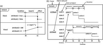
There are two approaches to modeling temporal aspects in a domain using timing diagrams. The first approach (Figure 4a), fully implemented in itSIMPLE, represents how attributes and properties change during an action execution. OCL expressions are used for defining such changes over a timeline. Only the objects related to the action can participate in the diagram. The concepts embodied by the diagram are closely related to durative-actions in PDDL and specify the conditions and effect of an action before, during, and after its execution. According to PDDL 3.1, there are three types of temporally annotated conditions and effects: at start specifies that a variable must have a specific value when the action is triggered; over all specifies that a variable has to hold its value during the execution of the action; and at end specifies that the variable must have a specific value at the end of the action.
Timing diagrams in itSIMPLE

An action represented in the timing diagram is mapped as a durative-action in PDDL by considering both the timing diagram and the state machine diagram. The latter provides the pre- and post-conditions while the former situates these conditions in the time window of the action. Properties and OCL expressions defined in the timing diagram are mapped to PDDL, quantified by one of the three PDDL temporal operators, depending on how they appear in the diagram. Any property or OCL expression that appears as a condition in the period before and at time t 0 (see Figure 4a) will be translated to PDDL and quantified by the at start temporal operator. Properties or OCL expressions between t 0 and t 1 will be annotated as over all type, and those defined after t 1 will be related to at end.
In the second approach to modeling temporal information, all objects are represented in a single diagram that encapsulates the deterministic state changes during specific periods of time. Each object receives a frame that is linked to a shared timeline representing the duration of the possible sequence of actions. Each object's state is linked to time points that represent its duration. Figure 4b shows an example of a timing diagram with two objects. Each object has its own life cycle that contains all its states and their durations. For example, consider a process of cleaning and painting a vehicle. A wash action could be applied at time t1 to a vehicle in a not-clean state that would hold until time t2 when the object would change to a wet state. The action dry could then take place at t2 making the object go from a wet to clean state at time t3. Paint would be performed in the clean state and would result in the vehicle being in the painted state at t4. This approach is not fully implemented in itSIMPLE; however, possible sequences of actions can be represented in the resulting PN. Modeling real-time constrains and their analysis using time-based PN are left for future work.
Mapping constraints: Constraints defined in a domain model represent rules that must be satisfied in any state of the domain and, therefore, in any valid plan. In UML, designers can represent constraints on several domain elements, for example, on properties of the classes and on how they relate to each other. In this work, we focus only on the constraints that can be represented in the class diagram in the form of invariants and rules that must be respected during the problem-solving process. For example, we considered the constraints found on the multiplicities of associations, which dictate how an object relates to other objects, and on OCL expressions annotated by users in elements of the class diagram that can explicitly specify invariants (inv:) (OMG, 2003).
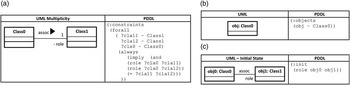
When an association has multiplicity ‘1’ on one of its edges, an object of a class can be associated with one and only one object of the other class. These kind of associations are represented as constraints in the section :constraints of a PDDL 3.0 domain (Gerevini & Long, Reference Gerevini and Long2006), using the always modifier. Figure 2 illustrates association at between Truck and Place. Such a constraint would be represented in PDDL as (:constraints (forall (?t-Truck ?p1-Place ?p2-Place) (always (imply (and (at ?t ?p1) (at ?t ?p2)) ( = ?p1 ?p2)))): if there is a place p1 that a truck is at and p2 that the truck is also at, then p1 and p2 must be the same place. The general mapping of such a constraint can be seen in Figure 5a. This type of constraint makes explicit what are usually implicit restrictions on an action's conditions and effects. itSIMPLE checks whether the specification of a planning problem meets the multiplicity constraints while users create object diagrams and associate elements.
(a) Mapping association multiplicity to PDDL constraints; (b) Mapping PDDL objects from object repository; (c) Mapping PDDL init from object diagram. PDDL = Planning Domain Definition Language; UML = Unified Modeling Language

Regarding invariants, users can specify constraints on classes, attributes, or associations in class diagrams by using OCL. For example, one could constrain the battery power level of a Robot by manually adding the following OCL expression to the class: inv: self.powerlevel<20. This expression would be represented in the domain section :constraints in PDDL 3.0 as (always (forall (?r-Robot) (< (powerlevel ?r) 20))). Another example is constraining the currentLoad of vehicle by providing the following in the Vehicle class: inv: self.currentLoad<0.8*self.capacity; meaning that the current load would never be >80% of the capacity. This constraint would be represented in PDDL as (always (forall (?v-Vehicle) (<(currentLoad ?v) (* (0.8) (capacity ?v))))).
3.2.2 Problem translation
A PDDL problem file generated by itSIMPLE can contain five primary elements: objects, initial state, goal conditions (objective state), problem constraints, and metrics. This information is found in the object diagrams of the UML representation. The procedure used for generating PDDL problems is shown below.
1 UMLtoPDDLproblem (xmlmodel, selectedproblem)
2 Map objects;
3 Map initial state;
4 Map goal;
5 Map exogenous events and problem constraints;
6 Map metrics;
7 return PDDLproblem;
Mapping objects: A dedicated object diagram, called the object repository, contains all objects used in a set of planning problems. Every object in the repository, along with the respective class name, is translated and inserted into the :object section of a PDDL problem file. The mapping rule for objects is shown in Figure 5b.
Mapping initial and goal states: Every problem instance has at least two object diagrams: init and goal. The translation process is the same for both diagrams. First, all object attributes and their values in the snapshot are represented in PDDL. For example, an object truck1 with attribute capacity of 100 would be represented as (= (capacity truck1) 100) in the :init section of PDDL. Since associations are treated as predicates, their translations are also straightforward. For instance, truck1 associated with place1 through association at in the object diagram would be mapped as (at truck1 place1). A general example of creating a PDDL state from object diagrams is presented in Figure 5c.
Mapping exogenous events and problem constraints: Additional object diagrams can be used to represent Timed Initial Literals (Edelkamp & Hoffmann, Reference Edelkamp and Hoffmann2004) and State Trajectory Constraints (Gerevini & Long, Reference Gerevini and Long2006). For the former, users create specific situations or facts in time using object diagrams for describing exogenous events. Each diagram is attached to a specific point in time with the meaning that all associations and attributes with their respective values will be true at that time point. This approach follows the same translation process as the state snapshots with the modification that elements are placed in the :init section preceded by the specified point in time (e.g., (at 5 (idle truck2)) in PDDL 2.2).
To model state trajectory constraints, users can also create object diagrams that represent required situations. Such object diagrams are annotated with the desired constraint using modal operators: always, sometime, at-most-once, and at end or never (always not). The whole snapshot is translated to PDDL as described above and inserted in the :constraints section of a PDDL 3.0 problem file attached to the desired modal operator. For example: (:constraints (and (always (<facts from the object diagram>)).
Mapping metrics: Finally, the user can write OCL expressions containing object attributes that define the quality of plans. Following the approach of mapping OCL expressions to PDDL conditions, itSIMPLE inserts the translated expression in the :metric section of PDDL. For example, a minimization of the expression ‘robot1.traveldistance + robot1.powerusage’ would be translated to (:metric minimize (+ (traveldistance robot1) (powerusage robot1))).
4 An overview of practical results
The itSIMPLE environment has been used to develop real planning applications in a number of domains.
• It was used to model and study the planning and scheduling of crude oil distribution in one of the biggest petroleum plants in Brazil, the São Sebastião Port (Vaquero et al., Reference Vaquero, Silva, Ferreira, Tonidandel and Beck2009b), which supplies the entire state of São Paulo. The planning process on such a plant encompasses activities such as the assignment of tankers to piers, unloading tankers into the terminal's tanks, and sending oil to refineries through pipelines. In this application, the main goal is to maintain the oil supply in the refineries while reducing operational costs at the port. To illustrate the size of the application, the resulting model had 9 types of objects, 20 predicates, 26 functions, and 11 operators (action schema). A daily problem instance could contain 13 tankers, 4 piers, 18 tanks, and 14 types of oil. More details can be seen in Sette et al. (Reference Sette, Vaquero, Park and Silva2008) and Vaquero et al. (Reference Vaquero, Silva, Ferreira, Tonidandel and Beck2009b).
• itSIMPLE has been used in the software development industry. It helps managers to plan and re-plan development activities, resource usage, and software production in a Lean Software Development approach (Udo et al., Reference Udo, Vaquero, Silva and Tonidandel2008). Managers use itSIMPLE not only for planning the development activities, but also to communicate the company's project management model to new development teams. In this application, the resulting model had 15 types of object, 26 predicates, and 8 operators. Problems instances could have 50 people and 80 software releases to deploy. Plans could reach 567 actions.
• Applications in the manufacturing field have also been studied, including car sequencing in an assembly line. In this application, inspired by RENAULT, the planning process is concerned with the generation of a sequence of cars to be painted and assembled. Following a daily request, the solutions must minimize the consumption of paint solvent while balancing workload on the assembly line (Vaquero et al., Reference Vaquero, Tonidandel, Barros and Silva2006). itSIMPLE was used to find a plan to this application based on specification documents provided by RENAULT manufacturing process planners. The resulting model had 7 types, 11 predicates, 12 functions, 5 complex actions, and different numbers of cars to be manufactured.
These practical experiences have shown that a direct specification in PDDL is not viable for real, complex applications. PDDL does not support KE, requirements gathering and analysis, or the elicitation of knowledge. The natural incompleteness and immaturity of the knowledge during the initial phases of design must be properly treated before being sent to solvers. PDDL is not yet a full specification language; a good discussion about the features of a specification language is provided by Frappier and Habrias (Reference Frappier and Habrias2001). As opposed to a direct PDDL specification, the work (Vaquero et al., Reference Vaquero, Silva and Beck2010) has shown that a disciplined modeling phase and a careful plan analysis process in itSIMPLE can significantly improve plan quality and increase planning speed of up to three order of magnitude. Moreover, these experiments and applications have validated itSIMPLE for designing domain models since it provides a useful environment for refining and sharing knowledge model among experts and non-experts.
5 Related work
Over the last 5 years, a few KE tools have been developed to assist the design process of planning applications and there has been an increasing interest on this area, as seen in recent workshops and competitions (e.g., the workshop and international competition series on Knowledge Engineering for Planning and Scheduling (KEPS)). Most of the recent work has focused either on general tools to support the overall design process regardless of the planning application or on tools for either specific phases of the design process or for a particular class of planning applications. As itSIMPLE is a general purpose tool, we focus our discussion on the former work.
The seminal general KE tool is the Graphical Interface for Planning with Objects (GIPO), under development since 2001 (Simpson et al., Reference Simpson, Mccluskey, Zhao, Aylett and Doniat2001). The tool aims to investigate and support the KE process in the building of applied AI planning systems. The purpose of GIPO project is to demonstrate the range and scope of tools required to support the KE aspects of planning domain creation (Simpson, Reference Simpson2007), helping designers to develop their domain models with an object-oriented approach. GIPO has been used to support teaching of AI planning to undergraduate students and is an influential research platform.
GIPO uses its own language, called Object-Centred Language Footnote 3, to model planning environments. GIPO permits observation, visualization, analysis, and validation of a planning domain model. However, real problems require a life cycle, and modeling is not the first step in a problem-solving process or in project development. Thus, even with object-oriented development tool for planning applications, it is still necessary to start from the requirements elicitation and analysis as in itSIMPLE.
ModPlan (Edelkamp & Mehler, Reference Edelkamp and Mehler2005) is a planning workbench that provides knowledge acquisition options to access and modify the outcome provided by static analyzers, together with visualization assistance to understand the validity of computed plans. The tool uses PDDL 2.2 as the base representation of the knowledge and it is aimed more at planning experts than designers with domain knowledge. In contrast to ModPlan, itSIMPLE focuses on an disciplined design process, mainly on initial design phases and PDDL is used as a means of communication with solvers rather than a central representation. In contrast to ModPlan and GIPO, itSIMPLE aims to use and integrate broadly used modeling languages to facilitate such initial phases and to make AI planning technologies more accessible to domain experts.
6 Future work
Future work will address improved support for RE via a process for the combination of the NO discipline and a dynamic analysis using PN. Currently, the system performs only liveness analysis with no multiplicity of marks in the PN. The intention is to replace the Elementary Net System presented in this work with an object-oriented high-level net. The advantages will be the use of the same class diagrams for static and dynamic verification. A new net approach has been created to address the formal dynamic verification of the domain model: General Hierarchical Enhanced Net System (GHENeSys; Silva et al., Reference Silva, Miralles, Salmon and del Foyo2009) is a unified net system that includes all PN extensions together with an object-oriented high-level approach. GHENeSys supports property analysis and model checking tools to validate requirements and features acquired in the early design phases. GHENeSys can also provide modeling features for representing time-based systems, using Timed PN, special algorithms to verify time constraints, for example, in scheduling problems, and can answer questions represented by well-formed formulas, which can be interpreted as reachability conditions.
We plan to improve the modeling capabilities by extending the types of UML diagrams that are supported. The timing diagrams will be enhanced and fully supported to properly gather timing constraints, such as timed sequences of actions. Such diagrams could be translated to Timed PN and further to PDDL. We will also include the UML activity diagram to acquire and model predefined planning strategies as well as the hierarchical decomposition of actions. Finally, even though the minimal set of representations has proved to be suitable for real applications, we plan to enhance the language set to increase expressibility using languages such as B (Ledang & Souquieres, Reference Ledang and Souquieres2002) or SysML (Bock, Reference Bock2006).
7 Conclusion
The development of integrated environments to support the design process for real-life planning systems is a research topic that connects the study of AI planning approaches and their application in real-life problems. This line of work combines engineering design, software engineering, formal methods, RE, KE, and AI planning. In this paper, we presented the itSIMPLE project, focusing on the design environment and translation processes currently available in itSIMPLE3.0. itSIMPLE is a KE tool that has been developed to support designers in the development of real planning domains. We have described how requirements modeled in UML are represented in XML can be analyzed using PN and then be translated to an input-ready PDDL model. The UML to PN translation opens the possibility to validate and analyze the model using simulation and model checking techniques. The translation from UML to PDDL provides a mechanism for testing and analyzing models with planners, providing the opportunity to improve models and, consequently, the quality of plans. The flexibility principle that allows a diverse set of representation languages and a variety of planning techniques makes the tool an interesting sandbox for new formal representations of planning domains and the development of new planning techniques.
Acknowledgement
The authors would like to acknowledge the organizers of the Third International Competition on Knowledge Engineering for Planning and Scheduling, and the anonymous reviewers for their useful comments which have greatly improved the manuscript. The authors would also like to acknowledge the students that contributed to itSIMPLE project. The first author would like to acknowledge CNPq and CAPES for the financial support.