NOMENCLATURE
- a
spline polynomial parameter
- AoA
angle-of-attack
- b
spline polynomial parameter
- CL
lift coefficient
- CD
drag coefficient
- Cf
skin friction coefficient
- Cl_o
lift coefficient for the original aerofoil
- Cl_m
lift coefficient for the morphed aerofoil
- Cd_o
drag coefficient for the original aerofoil
- Cd_m
drag coefficient for the morphed aerofoil
- CD
wing drag coefficient
- Cp
pressure coefficient
- ε
percentage of improvement
- Ff
optimisation fitness or objective function
- wi
fitness function weights
- f(x)
exact function that describes the curve to be interpolated
- h
spline interval
- I
integral of the exact function approximated by the spline interpolation
- m
spline polynomial slope
- M
Mach number
- Pn
spline polynomial of nth degree
- Re
Reynolds number
- Tr
non-dimensional transition x coordinate
- xi
x coordinate of the spline points
- yi
y coordinate of the spline point
1.0 INTRODUCTION
Reducing fuel consumption has become a central concern around the world due to the detrimental environmental effects of emissions as well as the significant costs involved in fuel extraction, transport and consumption(Reference Okamoto, Rhee, Nikos and Mourtos1,Reference Kwan and Rutherford2) . The search for the best solutions to reduce aircraft fuel consumption has therefore captured the attention of industry, academia and government institutions.
Most of the major research projects in the aerospace industry were undertaken by research consortiums such as the CRIAQ (Consortium for Research and Innovation in Quebec) and the GARDN (Green Aviation Research and Development Network) in Canada, and the Clean Sky project in Europe. There are many other collaborations between aerospace companies and universities throughout the world.
The active modification of the wing geometry, or “wing morphing”, is an example of Green Aircraft Technology. Previously, the only projects that investigated active wing morphing to improve aerodynamic performance (e.g. in STOL) were (mostly) limited to military aviation. Some of these projects were applied on the Grumann F-14, which has a varying sweep-angle wing design(3), the North American Aviation XB-70 Valkyrie prototype, which uses a ‘drooping’ wing tip that helped trap the shock wave under the wing between the downturned wing tips and also added more vertical surface to the aircraft to improve directional stability at high speeds(Reference Talay4), and the AFTI/F-111 ‘Mission Adaptive Wing’, which has an advanced supercritical wing design that uses a smooth variable wing camber to change the wing shape(Reference Bonnema and Smith5,Reference Smith and Nelson6) .
An extensive bibliographical review of morphing wing projects is presented in Sofla et al(Reference Sofla, Meguid, Tan and Yeo7) and Barbarino et al(Reference Barbarino, Bilgen, Ajaj, Friswell and Inman8). Many morphing wing projects, such as those presented by Blondeau et al, Bharti et al and Shili et al(Reference Blondeau, Richeson, Darryll and Pines9-Reference Shili, Wenjie and Shujun11) focus more on the mechanical-structural capabilities of their morphing configurations and less on the aerodynamic gains that can be obtained from these configurations. However, several projects have used numerical analysis, wind tunnel tests or even flight tests to demonstrate the validity of the morphing wing concept from an aerodynamic point of view as well(Reference Secanell, Suleman and Gamboa12-Reference Diodati, Ricci, De Gaspari, Huvelin, Dumont and Godard15). Pecora et al also discusses, proposes and validates several concepts for morphing trailing edges for future development of wings with adaptive high-lift devices(Reference Pecora, Amoroso and Lecce16-Reference Pecora, Barbarino, Lecce and Russo18).
Due to the time involved in developing and testing morphing wing concepts, some projects have concentrated on UAV wing modifications, as unmanned aerial vehicles started to play a more important role in military and agricultural operations. They are considered safer to research different configurations and the results can be implemented faster than on civil aircraft(Reference Sugar Gabor, Koreanschi and Botez19-Reference Sugar Gabor, Koreanschi and Botez22).
In 2002, the Aerospace Industry Association of Canada, the government of Quebec and key university research centres formed the CRIAQ to encourage mostly civil aviation research. One of their recent projects, called CRIAQ 7.1, was focused on shape changing wings and was realised between Canadian aerospace industry companies such as Bombardier and Thales; the IAR-NRC Research Center; and two universities, the École de Téchnologie Supérieure and École Polytechnique(Reference Botez, Molaret and Laurendeau23-Reference Grigorie, Popov, Botez, Mamou and Mébarki25).
The purpose of project CRIAQ 7.1 was to prove that controlling the position of the transition point and pushing it towards the trailing edge using shape-changing techniques can reduce the drag coefficient, and implicitly, fuel consumption(Reference Coutu, Brailovski and Terriault26-Reference Silisteanu and Botez28). As shown in the obtained results, it is possible to obtain up to 40% laminar flow improvement on a laminar aerofoil-based wing model, and at the same time to achieve a drag coefficient reduction of up to 20% by using active control with smart material alloy actuators (SMA). A subsequent aeroelastic study proved that the morphing technique would not induce flutter phenomena during wind tunnel testing(Reference Courchesne, Popov and Botez29). In addition, many breakthroughs were achieved in active open-loop and closed-loop control using Proportional Integration (PI)(Reference Popov, Botez, Grigorie, Mamou and Mebarki30,Reference Popov, Labib, Fays and Botez31) and fuzzy-logic-based controllers in wind tunnel testing(Reference Popov, Botez, Grigorie, Mamou and Mebarki32-Reference Grigorie, Botez and Popov34) under the auspices of this same project.
The research presented here was completed in the frame of the CRIAQ MDO 505 project, an international collaboration between Canadian and Italian industries, universities and research centres. The collaboration is between Bombardier Aerospace, Thales and Alenia Aeronautica on the industry side and École de Téchnologie Supérieure (ETS), École Polytechnique, CNRC, the University of Naples and CIRA on the academic and research institutes side. This project is a continuation of the CRIAQ 7.1 project.
The purpose of the project is to demonstrate the structural, aerodynamic and control abilities of a wing tip equipped with an adaptive upper surface and an adaptive aileron during low speed (subsonic) wind tunnel tests. The novelty of the project consists in the design, analysis and manufacturing of an aerodynamically and structurally optimised real wing tip. For all performed research, the wing tip was isolated from the rest of the wing and therefore it will be named the wing model in the present paper.
The wing model was tested for structural 1g loads, and, during these tests, the composite upper surface and the adaptive aileron were controlled with electrical actuators situated in the wing model and in the aileron boxes.
The present paper addresses the aerodynamic optimisation of the aerofoil component of the wing model using the adaptive upper surface. The purpose of this optimisation is the reduction of the drag coefficient and, for control and visualisation purposes in future wind tunnel testing, the extension of the laminar flow regime on the upper surface of the wing model.
The paper is divided into six parts: a review of the CRIAQ MDO 505 project concept, a review of the base aerofoil performances, description of the ‘in-house’ developed genetic algorithm method, presentation and discussion of the optimisation results for the base aerofoil, presentation and discussion of the aerofoil's optimisation impact on the wing model's performances, and conclusions.
2.0 REVIEW OF THE CRIAQ MDO 505 PROJECT CONCEPT
The CRIAQ MDO 505 project continues the CRIAQ 7.1 project's adaptive upper-surface wing concept and adds a real wing-tip structure, structural optimisation, new aerodynamic optimisation constraints, new control challenges, electrical actuation system, and classic and adaptive ailerons.
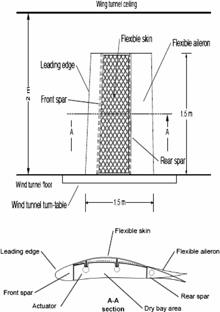
The full-scale wing model is an optimised structure with a 1.5m span and a 1.5m root chord, including its aileron, with a taper ratio of 0.72 and a leading-edge sweep of 8°.
The wing model box and internal structure is manufactured from aluminium with the composite adaptive upper surface extending from 20% to 65% of the wing model chord. The adaptive upper surface (skin) is specifically designed and optimised for this project as a carbon composite skin. The actuators are also specifically designed and manufactured to the project requirements. Four electric actuators are installed on two actuation lines, fixed to the centreribs and to the composite skin. Each actuator is capable of independent action. On each line the actuators are situated at 32% and 48% of the chord. These actuator positions were selected after analysing several other possibilities. From the analysis it was observed that positioning the actuators at equal distances from the ends of the composite skin returned the best results in term of aerofoil optimisation. These actuator positions also represent the optimisation points used during aerodynamic optimisation. The aileron's articulation is situated at 72% of the chord. Figure 1 presents a sketch of the wing model concept.
CRIAQ MDO 505 wing-tip concept sketch.

3.0 BASE AEROFOIL PERFORMANCES
The aerofoil (base aerofoil), on which the wing model is based, was provided by one of the industrial partners and is a modified version of a supercritical aerofoil. Figure 2 presents the base aerofoil in non-dimensional coordinates.
Base aerofoil.
The base aerofoil performance was evaluated with XFoil 6.96, an aerodynamic solver that is used for all aerofoil analyses throughout this paper. XFoil was developed by Drela and Youngren(Reference Drela and Youngren35) and was chosen to be used in this paper because of its precision, effectiveness and rapid convergence. It is a solver that permits both inviscid and viscous analyses as well as geometrical modification of the aerofoil. The inviscid calculation is performed with a linear vorticity stream function panel method(Reference Drela36), to which a Karman-Tsien compressibility correction is added, allowing for good subsonic flow prediction. For its viscous calculations a two-equation lagged dissipation integral boundary layer formulation(Reference Drela37) is used, which incorporates the en transition criterion(Reference Drela38). The flow in the boundary layer and in the wake interacts with the inviscid potential flow by means of a surface transpiration model.
Figures 3 presents the pressure distribution results for the base aerofoil, for an angle-of-attack range between –3° and 3° at Mach 0.15 and a Reynolds number of 2.15E+06.
Pressure distributions for Reynolds number of 2.15E+06.
4.0 OPTIMISATION ALGORITHM
An ‘in-house’ genetic algorithm software was developed to optimise the base aerofoil's drag and transition. The genetic algorithm was chosen because of its ability to give a great number of possible solutions and obtain a global optimum in each case.
A genetic algorithm is a meta-heuristic method inspired from the process of natural selection. It is an iterative method that necessitates a high number of individuals and several generations to achieve its convergence; both the number of individuals and the number of generations are problem-dependent.
In a simple version of a genetic algorithm, a first generation of individuals, represented by their genes, is created randomly. The genes that represent each of the individuals are chosen based on their abilities to change at each generation, towards attaining the proposed objective. The first random generation is evaluated, and then a fitness value is associated with each individual. The fitness value is based on the results obtained from comparison with the objective requirements. Random individuals are then chosen as parents based on their fitness values. Through a simple mixing of their genes (with the simplest method being that of associating 50% of the genes from each parent to the children), new individuals are created. The sum of the new individuals forms a new generation. The process is repeated until a certain number of generations has passed or until the fitness value has reached a user-imposed limit(Reference Mitchell39-Reference Whitley41).
In the ‘in-house’ version of the algorithm, the individuals are represented by aerofoils and the genes that characterise them are the vertical displacements of the actuators situated at 32% and 48% of the chord. The fitness value of each individual aerofoil is calculated from a fitness function based on its aerodynamic performances. A first version of this ‘in-house’ genetic algorithm was used in Sugar et al(Reference Sugar Gabor, Koreanschi and Botez42).
Figure 4 presents the logic flow diagram of the genetic algorithm used for the aerofoil optimisation.
Logic flow diagram of the genetic algorithm coupled with XFoil.
The aerodynamic performances are evaluated with XFoil 6.96 and are represented by the lift coefficient, CL, the drag coefficient, CD, the transition position and the skin friction coefficient variation with the chord, Cf. Based on these characteristics and the behaviour to be improved, single objective functions were developed and grouped in a fitness function to allow the selection of more than one objective if desired. The functions were developed on the most desired objectives encountered for aerofoil optimisation, for example: delaying transition for a more laminar flow on the upper surface, minimisation of the drag coefficient or maximising or minimising the lift in case of optimisation of a multi element aerofoil:
 $$\begin{equation}
\begin{array}{l} {F_f} &=& {w_1}({C_{l\_m}} - {C_{l\_o}}) + {w_2}\frac{{{C_{l\_m}}}}{{{C_{l\_o}}}} + {w_3}{C_l} + {w_4}\frac{{{C_l}}}{{{C_d}}}\\
&&+{w_5}\frac{1}{{{C_d}^2}} + {w_6}\frac{{Tr}}{{{C_d}}} + {w_7}Tr + {w_8}\frac{1}{{Tr}} + {w_9}{C_f},\end{array}
\end{equation}$$
where the values of wi represent the weight associated with the searched-for aerodynamic characteristic. The weights are chosen by the user based on the importance attached to each aerodynamic characteristic it wants to optimise. The weights can have positive or negative values, but the sum of all the weights in the fitness function should not exceed the absolute value of 100, which corresponds to attaching 100% importance to an objective in detriment of the others.
Although some of the objective functions might seem to be redundant, actually they explore different behaviour combinations. For example, if a double objective of maximising lift and minimising drag is searched, one can either work with two objective functions, giving them weight based on the importance attached to both lift and drag, or the user could choose one objective function that contains both terms, thus giving them equal value or letting the optimisation program to find the best combination of lift and drag.
To analyse, XFoil needs the aerofoil coordinates, but the optimisation algorithm only returns the vertical displacements of the points where the actuators are situated. As such, a reconstruction method that enforces a tangency condition as well as an iso arc-length condition is necessary for the upper surface of the aerofoil (between 20% and 65% of the chord, corresponding to the flexible skin); the other coordinates are kept identical to those of the base aerofoil. The reconstruction is incorporated in the optimisation algorithm.
Several different parameterisation techniques have been developed and applied over the years for aerofoil design, such as the polynomial representation(Reference Abbott and Doenhof43), the CST method created by Kulfan(Reference Kulfan and Bussoletti44), and Non-Uniform Rational B-Splines(Reference Berbente, Mitran and Zancu46). However, these methods either parameterise the complete aerofoil and thus are not able to represent only a limited part of it, or they are difficult to implement when only the reconstruction of a specific part is required. They are also not judged sufficiently time-efficient to solve the problem presented here. Therefore, spline functions(47,Reference Herrera, Lozano and Verdegay48) were selected for the reconstruction of the upper surface of the wing model aerofoil.
The best-known spline interpolation is the ‘cubic spline’, which ensures continuity up to and including second-order derivatives and allows for the calculation of the curvature radius. Finch and Friswell(Reference Fincham and Friswell49) use a cubic spline interpolation for their morphing trailing-edge system.
The cubic spline is represented by the third-degree polynomial:
 $$\begin{equation}
{P_{3,i}}(x) = {y_i} + {m_i}(x - {x_i}) + {b_i}{(x - {x_i})^2} + {a_i}{(x - {x_i})^3},
\end{equation}$$
which describes the behaviour of the splines at each interval hi (Equation 4).
The parameters ai and bi are functions of the slope mi calculated in each node i. The slope is the solution to the tri-diagonal linear system:
 $$\begin{equation}
{\rho _i}{m_{i - 1}} + 2{m_i} + {\lambda _i}{m_{i + 1}} = {d_i},{\rm{ }}i \in \overline {2,(N - 2)} ,
\end{equation}$$
where
 $$\begin{equation}
\begin{array}{l} {\rho _i} = \frac{\displaystyle{{h_i}}}{\displaystyle{{h_{i - 1}} + {h_i}}},{\rm{ }}{\lambda _i} = 1 - {\rho _i},{\rm{ }}{d_i} = \frac{\displaystyle{3{\lambda _i}({y_{i + 1}} - {y_i})}}{\displaystyle{{h_i}}} + \frac{\displaystyle{{\rho _i}({y_i} - {y_{i - 1}})}}{\displaystyle{{h_{i - 1}}}}\\ {h_i} = {x_{i + 1}} - {x_i}; \end{array}
\end{equation}$$
to which we add relations that replace the continuity conditions for the first and second derivatives that cannot be imposed on xN. These conditions could either be imposed as values for the end slopes m1 and mN , or they could be given in a more general form, through relations with their neighbouring slopes.
For our problem, we have chosen to add the continuity conditions in this more general form through relations with their neighbouring slopes using a particular case of the cubic spline interpolation, namely, the ‘natural cubic spline interpolation’, and which is defined by the following conditions at the ends xi:
 $$\begin{equation}
{P^{\prime\prime}}({x_1}) = {P^{\prime\prime}}({x_N}) = 0
\end{equation}$$
By replacing Equation (5) in Equation (3) we obtain the following linear system for the end slopes m1 and mN:
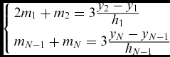 $$\begin{equation}
\left\{\begin{array}{l} 2{m_1} + {m_2} = 3\frac{\displaystyle{{y_2} - {y_1}}}{\displaystyle{{h_1}}}\\[6pt] {m_{N - 1}} + {m_N} = 3\frac{\displaystyle{{y_N} - {y_{N - 1}}}}{\displaystyle{{h_{N - 1}}}} \end{array} \right.
\end{equation}$$
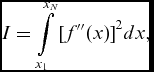
By imposing these conditions, the following integral is minimised:
 $$\begin{equation}
I = \int\limits_{{x_1}}^{{x_N}} {{{[{f^{\prime\prime}}(x)]}^2}dx} ,
\end{equation}$$
where f(x) is the exact function that is approximated by the spline interpolation. Minimising the above integral by imposing the natural conditions (Equation 5) produces the smoothest cubic spline interpolation; therefore, this type of interpolation is chosen to reconstruct the aerofoil shapes.
After the reconstruction of the aerofoils based on the vertical displacements of the actuation points and analysed with XFoil, the aerofoils are evaluated with the fitness function. Based on their results, they are graded from 1 to 10, where 10 is the grade given to the best aerofoil.
The next generation of aerofoils is created from the present one, with each aerofoil in the current generation having at least one chance at being selected as parent.
To ensure that the choice of the parents is random, and thus to give the most chances to those aerofoils with higher grades, a probability function was created, which returns values between 1 and 10.
 $$\begin{equation}
{P_S} = 11 - \max (\min ({({\mathop{\rm int}} (random(0) \cdot {10^{\frac{1}{{{A_t}}}}}))^{{A_t}}},10),1)
\end{equation}$$
The obtained value is then compared with the grades of each aerofoil, and those grades that match it are grouped. From this group one aerofoil is randomly chosen as ‘parent’. The process is repeated for a number of times that is equal to the number of parents used to create the new aerofoil. In our case, we used the classical approach of one ‘mother’ and one ‘father’.
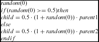
When all the parents are chosen, they are passed through the cross-over and mutation processes(Reference Deb and Agrawal50). The ‘cross-over routine’ used has a two-steps approach. For the first 10 generations, the genes of the parents are mixed in equal proportions. This first step hastens the convergence process and leads the optimisation towards the global optimum area. The second step, applied for the remaining number of generations, is a cross-over function derived from a simulated binary cross-over technique(Reference Deperrois51) coupled with a ‘random number generator’ function.
 $$\begin{equation}
\begin{array}{l} random(0)\\ if(random(0) > = 0.5)then\\ child = 0.5 \cdot (1 + random(0)) \cdot parent1\\ else\\ child = 0.5 \cdot (1 + random(0)) \cdot parent2\\ endif \end{array}
\end{equation}$$
This second step is used to pinpoint, as accurately as possible, the best solution from the multitude of solutions found in the global optimum area.
Each new aerofoil in each generation is passed through a ‘mutation routine’ in which, based on the probability of occurrence (which is a value introduced by the user – 0.1% from the individuals in a generation in our case), is affected by gene mutation.
The mutation process, if it occurs, depends on the amplitude of mutation (also user-dependent), which in turn depends on the value to be mutated. The amplitude of mutation is usually a small percentage (2% in this case) of the gene's values derived after cross-over.
From mutation, the new aerofoils are passed through a verification process. Here, are verified the conditions related to actuator's maximum and minimum displacements and delta values between the actuator displacements. The conditions are derived from multidisciplinary work, as they are provided from aerodynamic, structural and control calculations and limitations.
If an aerofoil fails the requirements, the selection, cross-over and mutation processes are reiterated until a valid aerofoil is obtained. If a certain number of iterations (10,000 is the value imposed for this specific problem) have passed without yielding valid results, the optimisation process stops.
Under normal conditions, the processes of selection, cross-over, mutation and verification are repeated for each pair of parents until a fixed number of aerofoils in a generation is reached. This number of aerofoils (also referred as generation) is set by the user at the beginning of the optimisation process.
The complete process of reconstruction, analysis and evaluation is repeated until the maximum number of generation is reached.
To improve the overall convergence of the optimisation process a tournament is introduced. A tournament takes place after the current generation is analysed and graded and before the creation of the new generation. The tournament compares the worst aerofoils from the current generation with the best ones from the previous generation and replaces the former with some of the latter, thus favouring the propagation of good genes from the older generation to the current and then on to the future generations.
This tournament process hastens the convergence of the optimisation and for our problem of optimising a specific part of the aerofoil it reduces the number of generations from 40 to 20 and the number of aerofoils in a generation from 50 to 40.
5.0 OPTIMISATION RESULTS FOR THE BASE AEROFOIL
The concept of an adaptive upper-surface wing model and the optimisation program were described in Sections 2 and 3. The adaptive upper surface extends from 20% to 65% of the chord and its length remains unchanged. The actuators are situated at 32% and 48% of the chord and their displacements are limited to ±5mm each, while the difference between the displacements of the actuators is limited to 6mm.
The aerodynamic analysis was carried out for a speed of 51m/s, equivalent to Mach 0.15 at sea level, and with a Reynolds number of 2.1E+06 with the aerofoil chord as the reference length. The angles of attack analysed with XFoil are local angles of attack, which are calculated for the specific area of the wing model where the actuator line is situated.
In this optimisation, the delay of the transition on the upper surface is chosen in order to obtain a more laminar flow, and only one objective function was used: transition. It was chosen because a side effect of delaying transition and creating a more laminar flow is the reduction of the drag value. Of course, any of the three objective functions that contain either drag, transition or both could have been chosen, as all will return an optimised aerofoil that is in the global optimum area, but since the main objective was transition delay, the transition function was chosen as the fittest for the problem.
 $$\begin{equation}
{F_f} = {w_7}Tr,
\end{equation}$$
where all other weights from Equation (1) are considered 0.
The optimisation process is done for each flight case, and for each case a different optimised shape is obtained.
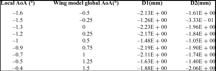
Table 1 presents the cases analysed for Mach number equal to 0.15 and the optimum actuators displacements obtained with the optimisation algorithm for each case (local angle-of-attack and corresponding global wing model angle-of-attack).
Analysed cases – actuator displacements
Figure 5 presents the comparison between the shapes obtained with the optimisation algorithm for four generations (5th, 10th, 15th and 20th, which is also the final) and the base aerofoil.
Comparison between the optimised aerofoil shapes and base aerofoil at Mach number of 0.15 and wing model global angle-of-attack a = 0°.
Figures 6–9 present the results expressed in terms of lift coefficient (Cl) versus global angle-of-attack, drag coefficient (Cd) versus lift coefficient, transition point versus global angle-of-attack, and transition point versus drag coefficient (Cd), respectively, as comparisons between the base and optimised aerofoil results.
Lift coefficient versus global angle-of-attack.
Drag coefficient versus lift coefficient.
Transition point versus global angle-of-attack.
Transition point versus drag coefficient.
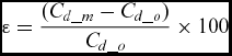
Since the objective of the optimisation was not the improvement of the lift coefficient and the modifications did not affect the overall curvature of the aerofoil, Fig. 6 confirms that there is no change in the values of the lift coefficients for any of the morphed results. From Figs 7–9, it can be deduced that the objective of optimising the aerofoil for drag coefficient and delay of the laminar flow transition was attained, and Fig. 10 shows the drag reduction versus the global angle-of-attack. The average drag coefficient reduction is approximately 2.3% for the nine cases here presented, while the average transition delay is approximately 3.3% for the same cases.
Drag coefficient improvements.
The reduction is calculated as the relative error between the morphed and the base aerofoils:
 $$\begin{equation}
\varepsilon = \frac{{({C_{d\_m}} - {C_{d\_o}})}}{{{C_{d\_o}}}} \times 100
\end{equation}$$
6.0 AEROFOIL OPTIMISATION IMPACT ON WING MODEL PERFORMANCES
To fully understand the impact of the results obtained on the aerofoil optimisation, an analysis of the wing model, with its geometry based on the optimised aerofoils, is done using the XFLR5 codeReference Deperrois51. XFLR5 is an analysis tool for aerofoils, wings and aircrafts operating at low Reynolds numbers. It includes XFoil's direct and inverse analysis capabilities, as well as wing design and analysis capabilities based on Lifting Line Theory(Reference Sivells and Neely52), the Vortex Lattice Method(Reference Maskew53) and the 3D Panel Method(Reference Katz and Plotkin54).
For the XFLR5 analysis of a wing, there are three steps to be followed:
1. Analysis of the aerofoil(s) composing the wing using a multi-threaded batch analysis, which allows the analysis of multiple aerofoils at a specific speed over a range of Reynolds numbers and ranges of angles of attack using XFLR5’s XFoil section.
2. Construction of the wing model, based on the aerofoil(s) analysed in the previous step. This step requires the number of sections (minimum of two root and tip sections), the span and chord dimensions for each section and, if present, the offset (m), dihedral and twist angles. Finally, the wing model needs the total number of panels required for the calculations in each direction for each section.
3. Analysis of the wing model using one of the following methods: Lifting Line Theory, the Horse-shoe Vortex Lattice Method, the Ring Vortex Lattice Method or the 3D Panel Method.
For the present analysis, the aerofoils are the base aerofoil and the aerofoils resulted from the optimisation process for each case. The wing model is created from four sections: sections 1 and 4, representing the root and the tip of the wing model –the corresponding aerofoil is the base aerofoil; and sections 2 and 3, which represent the actuator lines in the span length – the aerofoils corresponding to them are the optimised aerofoils, specific for each studied flight case.
Figure 11 presents the wing model for one flight case as it was created using XFLR5.
Wing model definition in XFLR5 for Mach 0.15 and angle-of-attack of 0.25°.
The analysis was done at the Mach number of 0.15 over the same range of global angles of attack as the optimised aerofoils, using the 3D Panels Method option for aerodynamic analysis. The 3D Panel Method was chosen because the other methods were considered as insufficiently accurate for the analysis. The Lifting Line Method works only for wings with aspect ratios greater than 4, while this wing model has an aspect ratio of 2.9. The Vortex Lattice Method reduces the body to a middle surface with zero thickness, which eliminates the notions of upper and lower surfaces and returns only the difference between upper- and lower-surface pressure coefficients. The 3D Panel Method takes into account the three-dimensional geometry surface and gives more detailed results for the studied geometry.
Figures 12–14 present the global reduction of the drag coefficient as indicated in the global CD versus lift coefficient, viscous CD versus lift coefficient, and inviscid CD versus lift coefficient graphs, for the original and morphed (optimised) wing model.
 $$\begin{equation}
{C_{D\_total}} = {C_{D\_viscous}} + {C_{D\_inviscid}}
\end{equation}$$
Wing model total drag coefficient versus lift coefficient for Mach 0.15.
Wing model viscous drag coefficient versus lift coefficient for Mach 0.15.
Wing model inviscid drag coefficient versus lift coefficient for Mach 0.15.
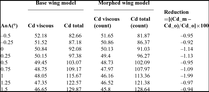
Table 2 shows the values of the global and viscous drag and the global drag reduction for Mach 0.15 and each angle-of-attack. The drag is presented in counts, where one drag count is equal to 10−4.
Total wing model's drag coefficient improvement
Figures 15 to 17 present the span distribution of the profile drag for each case analysed, showing the difference between the original and the morphed wing models. The profile drag is the most affected by any modification in the aerofoil shape. Here, it is presented in counts, where one count represents 10−4.
Profile shape drag versus wing model span – angles of attack –0.5° to 0.25°.
Profile shape drag versus wing model span – angles of attack 0.5° to 1.25°.
Profile shape drag versus wing model span – angle-of-attack 1.5°.
The figures presented above show that even though the morphing area is situated only in the space between the spars of the wing model and the displacements are quite small, an overall wing model drag improvement takes place for all of the studied cases.
Each case shows that the main reduction is concentrated in the region between the actuation lines, which are situated at 0.56m and 1.117m along the span as presented in section 2 of this paper.
An exception is the case corresponding to Mach 0.15 angle-of-attack a equal to 1° where a numerical error appears which affects the value of the drag coefficient in small measure. Most probably the reduction is less than 2%, but as the trend shown in Fig. 16 is similar to the others, it can be assumed that there is an approximately 1% reduction for it as well.
7.0 CONCLUSIONS
This paper has indicated how the shape optimisation of the aerofoil component of a wing model can be achieved using an adaptive upper surface approach. The goal was to conduct single-point optimisation of the drag characteristics of the aerofoil and to analyse its effects on the overall wing model drag characteristics. To achieve this objective, an optimisation routine was developed based on a genetic algorithm and coupled with the XFoil 6.96 solver for the aerodynamic analysis of the resulting optimised aerofoils. Several constraints were taken into account based on an aerodynamic-structural-control multidisciplinary optimisation approach.
The results revealed that a delay in the transition of the laminar flow over the aerofoil upper surface can be achieved with small displacements of –2mm, as well as the reduction of the drag coefficient of the aerofoil component. To evaluate the impact of these improvements on the wing model, the wing model performance was analysed using the open-source solver XFLR5, utilising the 3D Panel Method incorporated in XFLR5. The results show a reduction of the drag coefficient of up to 2% from the original wing model shape, and Figs 15 to 17 show that this improvement mainly comes from and is concentrated in the morphing region of the wing model between the two actuation lines. Overall, aerofoil optimisation has proven its utility, and in particular, the laminar flow behaviour of the boundary layer is improved, as shown in Figs 10 and 11. Further studies of the morphing wing model will include the introduction of an adaptive aileron and the combined optimisation of adaptive upper surfaces and adaptive aileron for various objectives.
ACKNOWLEDGEMENTS
We would like to indicate our appreciation for the financial support obtained in the framework of the CRIAQ MDO-505 project and for the implication of our industrial partners Bombardier Aerospace and Thales Canada. We also wish to thank NSERC for their support.
Special thanks are dues to our collaborators and leaders in this project: Mr. Patrick Germain and Mr. Fassi Kafyeke from Bombardier Aerospace, Mr. Philippe Molaret from Thalès Canada, and Mr. Eric Laurendeau from École Polytechnique.