1. INTRODUCTION
The British Antarctic Survey (BAS) regularly conducts airborne surveys in the Polar Regions, from our Twin Otter aircraft. Two of our aircraft can be fitted out with a wide variety of instruments to collect scientific data. This includes:
-
• Photographic survey using the Intergraph Digital Mapping Camera (DMC) (Fox and Cziferszky, Reference Fox and Cziferszky2008; Fox and Gooch, Reference Fox and Gooch2001).
-
• Gravity survey using a modified LaCoste and Romberg (L&R) gravimeter made by the ZLS corporation (Jordan, Reference Jordan2007; Reference Jordan2010).
-
• Light Direction and Ranging (LIDAR) survey using either Leica or Optech systems (Ferraccioli, Reference Ferraccioli2014).
-
• Synthetic Aperture Radar (SAR) radar survey using a 150 Mhz in-house system Polarimetric Radar Airborne Science Instrument (PASIN) (Ross, Reference Ross2012; Corr, Reference Corr2007).
-
• Magnetic survey using a caesium magnetometer system (Ferraccioli, Reference Ferraccioli2007, Reference Ferraccioli2011).
A typical survey will be conducted over a period of days or weeks, based from a field camp or base. Many of the surveys are conducted over the Antarctic plateau; a vast, snow covered, white, landscape with very few visual features to aid in accurate visual flying. Pilot guidance instrumentation is key to the collection of valid survey data.
1.1. Challenges of navigation for an Antarctic airborne survey
Each of the commercial survey instruments includes a different avionics navigation system and display. These systems have their own unique pilot interfaces, control interfaces, and different proprietary file formats for their configuration and maps. Each has its own benefits and disadvantages. This lack of commonality between systems creates complexity when managing and planning each survey. More seriously, the lack of a common pilot interface is a significant training problem for our pilots and ultimately reduces our operational flexibility and potentially impairs their flying performance. This problem is only exacerbated in a typical multi-instrument survey where a pilot may be expected to alternate between systems.
Further complications are introduced by the varying optimal conditions for data collection between different systems. For airborne gravity using the L&R ZLS system, flights must be at a constant altitude with minimal vertical acceleration. Lateral acceleration also degrades the performance of the instrument, so wide flat turns are required (Jordan, Reference Jordan2007). In contrast many other surveys require draped flight, i.e. maintenance of a constant ground clearance, rather than constant altitude. For magnetic surveys draped flight is required to ensure consistent recovery of all wavelengths. For LIDAR and aerial photographic surveys draped flight ensures appropriate overlap of observations to allow the creation of a seamless mosaic of data. For these surveys, turns between lines need to be as efficient as possible, while maintaining lock to GPS navigation satellites. However, in some circumstances variations in elevation exceed aircraft performance and draped flight planning must consider both terrain and aircraft performance (Jordan, Reference Jordan2014).
1.2. The solution is ASCEND (Airborne Survey Navigation Device)
Our solution is to design an avionics survey navigation system that can be used with all of our survey instruments. This allows us to capture the best of each of the commercial avionics, as well as the requirements of our pilots and scientists, into one system.
2. ASCEND REQUIREMENTS
ASCEND has the following requirements:
-
• Compatible with different co-ordinate transforms, including polar stereographic and earth geocentric.
-
• Compatible with different map formats and modes of navigation.
-
• Support for high precision, high frequency positioning systems via a standard National Marine Electronics Association (NMEA) string interface.
-
• Real-time operation. ASCEND is part of a control loop connecting the Global Positioning System (GPS), ASCEND, the pilot and the aircraft. Any significant delay in the response of any component will make it difficult to accurately follow a survey line and ultimately result in a sub-optimal survey.
-
• Mission planning capabilities for flying time and fuel consumption prediction.
-
• Support for different display hardware. Each of the existing avionics systems has included its own compact display that can be mounted within the cockpit, something which creates the need for additional safety certification. The BAS Twin Otters are being upgraded, replacing their analogue cockpit displays with electronic screens or “glass cockpits”. This upgrade includes the capability to project a generic Video Graphics Array (VGA)/video input onto one of the screens. This feature will make it possible for ASCEND to provide navigation instructions to the pilot without any additional hardware being needed to be installed in the cockpit.
-
• Ability to easily adapt the pilot display for different pilot requirements.
Though it is technically possible for ASCEND to provide inputs to an autopilot, at present BAS is intending to fly ASCEND in de Havilland Canada DHC-6 Twin Otters which are not fitted with autopilots. Such a feature may be of interest in the future but this development would require testing and aviation certification for flight safety and mission critical applications. Instead, the development of ASCEND will focus on being an easy to use, flexible platform for pilot guidance, and so will be tested against criteria relevant to achieving accurate survey flying.
3. ASCEND STRUCTURE
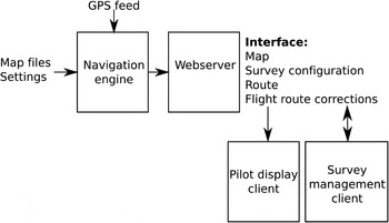
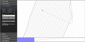
ASCEND consists of a navigation engine responsible for generating maps, courses and course correction data, a webserver for sharing this data, a pilot display interface and a survey management interface (see Figure 1). Each of these client interfaces are rendered as webpages from HTML and JavaScript. Using a standard webserver infrastructure means that ASCEND is easy to setup on different hardware, and simple to scale across both small and large survey infrastructures. The webserver architecture also allows for multiple copies of each display client to be opened simultaneously, if for instance there are multiple crew requiring a visualisation of the survey mission.
Overview of ASCEND structure.

The HTML client format makes it trivial to modify the display interfaces according to the requirements of the pilot, the survey type or the display hardware. The different requirements of each pilot can be quickly rendered, in flight if necessary.
4. MAPPING AND ROUTE PLANNING
ASCEND first prepares the necessary coordinate transforms to convert the survey plan, any map overlays, and the latitude/longitude values from the GPS, into the co-ordinate scheme required for the type of survey. This is then scaled and translated to fit within a unitary X-Y space. All navigation and routine calculations are performed within this space, and the results are shared with the client interfaces via the webserver. Each client interface then scales this space up to fit the desired display hardware.
4.1. Navigating to the start of a survey line
Much of an Antarctic survey flight is flying from a fuel cache or field camp to the start of a survey line, or flying from the end of one survey line to the start of the next. The ability to efficiently route the aircraft is an important part of survey navigation, but the restrictions imposed on aircraft manoeuvrability by the aircraft platform, and by the survey requirements, create additional complexity. For instance, the gravity sensor is sensitive to sudden accelerations, so any aircraft turns must be slow (less than one degree per second) and flat, only using the tail rudder. The synthetic aperture radar is less sensitive to acceleration, but any aircraft turns must still be slower than three degrees per second. However, a photographic survey is not affected by acceleration, so places no restrictions on the aircraft manoeuvrability. The ability to capture these turning restrictions and plan a route accordingly is a feature that is missing from all of the commercial avionics systems we have tested.
ASCEND overlays two turning circles between the aircraft and the start of the next survey line. The radius of these turning circles is calculated from the maximum turn rate and the speed of the aircraft, and can be modified in flight if necessary. One turning circle is placed immediately adjacent to the aircraft, the other is placed adjacent to the start of the survey line, offset with a specified run-in distance. ASCEND then calculates the four possible intercepts that are tangent to both circles.
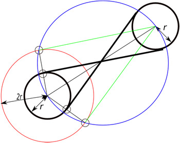
Figure 2 shows the geometrical method used to find the two inner tangents. First the intersection is found between two circles, the red circle which is centred on the first turning circle and twice its radius, and the blue circle whose perimeter intersects with the centre of each turning circle. Each intersection forms a triangle from the radii of each circle and the gap between the centres of each circle, so these are simple to find using the cosine law.
Finding the inner tangents between two turning circles.

Each line (green in Figure 2) connecting these intersections to the centre of the opposing turning circle, will be parallel to the desired inner tangents. The start point for each tangent is half way between these intersections and the centre of the turning circle. This is an application of Thales' theorem (Casey, Reference Casey1888).
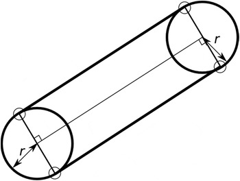
Because each turning circle has the same radius, the outer tangents will be parallel to a line connecting the centres of each turning circle, and offset by a distance r, as seen in Figure 3.
Finding the outer tangent between two turning circles

Finally ASCEND selects the most appropriate tangent and directs the pilot to follow it. This ensures the shortest path is followed within the constraints of the survey. This turn planning can be updated dynamically in response to each new aircraft position, or it can be calculated statically as part of pre-flight survey planning.
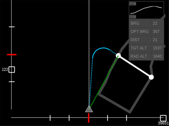
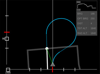
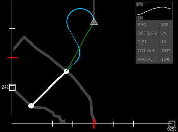
Figures 4, 5 and 6 are examples of ASCEND navigating the aircraft to the start of a survey line. The triangle represents the aircraft, the grey vertical line is its heading, the thick grey line is the perimeter of the survey area and the white line is the target survey line. The blue line shows an optimum route for navigating to the start of the survey line. The line in the top right corner of the display is an elevation map that follows the survey line.
Navigating to the start of a survey line that is ahead and to the right of the aircraft.

Navigating to the start of a survey line that the aircraft is too close to be able to turn onto with the specified turning circle radius.

Navigating to the start of a survey line that is behind the aircraft.

4.2. Following a survey line
A survey line is defined as a straight line connecting two points in an X-Y plane in any of the supported co-ordinate schemes. The z-axis of this survey line can either be a fixed altitude, or a fixed distance above ground, following a varying Digital Elevation Map (DEM).
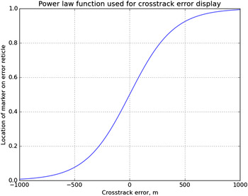
The pilot following a survey line needs to know their cross track error in both axis, as well as having some indication of future altitude changes. Commercial avionics systems display this cross track error as a two-axis reticule. Some displays switch between different scales so that the cross track error is never beyond the bounds of the reticule, others use a combination of linear and logarithmic scales. The ASCEND reticule scaling function is defined in a JavaScript routine that is simple to modify to meet the preference of the pilot. During trials we tried both the scale switching, linear and logarithmic scales; however the current preference is for a power-law function defined in Equation (1) and shown in Figure 7.
 $${y} = \displaystyle{1 \over {1 + {{e}^{ - 0 \cdot 005{x}}}}}$$
Power law function used to display cross track error on the pilot display reticule.

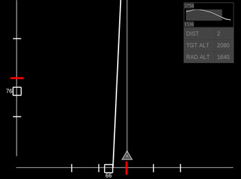
Figure 8 shows a typical survey flight display following a line with a varying altitude profile defined by a DEM. Figure 9 shows the same flight as seen on the survey management client. Note that the DEM on the bottom of the display appears reversed when compared to Figure 8 - this is because the pilot display orientates the maps and DEMs along the relative direction of the aircraft, while the management client does not.
Following a survey line.

Following a survey line from the survey management client.

4.3. Pre-flight route planning
A key part of survey planning is determining the optimal sequence of survey lines such that a minimum of fuel is used. This is particularly important in remote parts of the Antarctic, where stockpiling fuel is one of the most expensive parts of the survey. Being able to optimise the sequence of survey lines in response to changing weather conditions is also important. Finally, it is necessary to estimate flight time and fuel consumption prior to each flight.
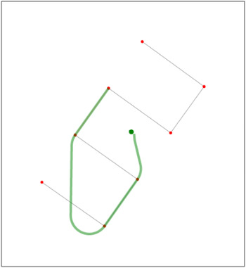
Usually a significant portion of any given survey flight may be used in navigating to the start of each survey line, and calculating this component is non-trivial. The dynamic navigation and turn generator described already can also be used in a static pre-flight planning mode. A sequence of locations (e.g. field camps) and survey lines is converted into a planned route with time and distance of flight calculations (see Figure 10).
Pre-flight survey planning.

This planned route can also be exported as a sequence of locations or a route file compatible with the Garmin 296 flight GPS systems used by our pilots. This provides a backup survey navigation system in the event that ASCEND fails.
4.4. Further ASCEND features
Some additional features include:
-
• A survey line can be dynamically extended by the survey manager, in the event that in-flight observations merit a prolonged line.
-
• The survey control interface shows a “snail-trail” of the progress of the aircraft throughout the survey.
-
• Post-flight survey analysis. After each survey line is complete, the proximity of the aircraft to the line can be computed, allowing the survey manager to quickly decide if parts of the survey need to be re-flown.
-
• Survey simulation. The survey route can be “flown” within a simple simulator. This can be used for training purposes. The simulator is also an end-to-end test mechanism, in that the simulator is emulating the GPS input source, so it can be used to evaluate the software or test an ASCEND installation.
-
• Historical flight records can also be used as an alternative to the GPS input, allowing for the in-flight ASCEND displays to be recreated.
5. ASCEND PERFORMANCE EVALUATION
5.1. Real-time testing
ASCEND is a component in a real-time feedback loop connecting the aircraft, the GPS receiver, ASCEND, the pilot and the aircraft controls. Any significant delays in this loop will make it much more difficult for a pilot to correct the aircraft flight path in order to follow a survey line accurately. Under ideal conditions, the mean human reaction time to a visual input is 180 ms (Macadam, Reference Macadam2003). Tests on pilots have shown that the time needed in order to detect and correctly respond to a visual input varies from 223 ms (F-14 fighter pilots (Morris and Hamilton, Reference Morris and Hamilton1986)) to 925 ms (long-haul commercial pilots (Hosman, Reference Hosman1996)). For ASCEND to be a useful instrument, it must respond to changes in aircraft orientation and position with an update time that is negligible in comparison to the pilot response times.
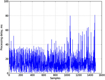
In order to measure the update time of ASCEND, we have implemented the server and a single client on a laptop (2·6 GHz Intel i5). Figure 11 shows the time taken from the ASCEND server receiving a GPS position from a receiver until the pilot display is updated. The two peaks visible in this graph correspond with the server performing re-routing calculations. The remaining variation in update time is because the webserver architecture is asynchronous, so the client interface cannot be synchronised to the GPS. The average time between receiving a position from the GPS and updating the pilot display accordingly is 14·6 milliseconds; this is more than fast enough - the reaction time of the pilot will dominate any survey correction error.
Real-time performance of ASCEND.

5.2. Flight trials
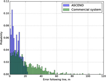
Twelve survey lines have been flown by two pilots as part of three flight trials of ASCEND at Rothera, Antarctica. Pilot A had previously been involved in its design specification and subsequently instructed in its use prior to the flight. Pilot B first saw ASCEND in flight. Figure 12 shows the accuracy of these pilots following a survey line using ASCEND, compared to a similar survey conducted using an existing commercial avionics platform. With the commercial avionics platform the average deviation from the survey line was 20 m, with ASCEND this average deviation was reduced to 8 m.
Comparison of system performance, distance from survey line followed by ASCEND and an existing commercial avionics platform.

Feedback from both pilots was unanimous in their approval, preferring it to the other commercially available systems. Pilot B was able to quickly understand the display and found it intuitive to use. However, their suggestions for display modifications placed them at odds with each other, requiring us to create two separate pilot interfaces, each customised to their requirements. Further discussions and demonstrations with another pilot again produced a different set of display requirements. These different displays were easy to create by modifying the HTML of a template pilot display.
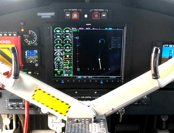
In August 2015 the first BAS Twin Otter completed an avionics upgrade which included the installation of a Garmin GDU 1500 console and display. This display is able to show an external video input (in National Television System Committee - NTSC format) alongside aircraft and engine management information. Figure 13 shows the ASCEND pilot screen being displayed on the Garmin Graphic Display Unit (GDU) via this external video input. A further two flight trials were conducted using this display configuration, these trials were a success and ASCEND is now considered ready for future Antarctic survey missions.
ASCEND displayed on the Garmin GDU1500.

6. CONCLUSIONS
ASCEND is a new avionics systems designed for multi-instrument airborne survey operations. It has been designed around the requirements of the British Antarctic Survey aircraft and survey instruments, but is sufficiently flexible to accommodate the requirements of different platforms, instruments and pilots.
Test flights have shown that ASCEND is intuitive to use and an effective survey guidance system that is ready for operational flights. We now intend to use ASCEND in three airborne survey missions planned for the 2015/16 Antarctic season. These include a photographic survey of Antarctic seal populations, a radar survey of the Filchner-Ronne ice stream, and a gravity and magnetometer survey centred around the South Pole.
We are committed to providing the ASCEND software to other parties who are interested in evaluating, using or improving upon the design.
ACKNOWLEDGEMENTS
The authors wish to thank Alan Meredith, Ian Potten, Andrew Vidamour, Victoria Auld, Mark Beasley and Hugh Corr for their contributions and assistance in the development of ASCEND.