NOMENCLATURE
- R
-
radius (m)
- V
-
absolute velocity(m)
- CP
-
pressure coefficient (/)
- CR
-
filling coefficient (/)
- T
-
temperature (K)
- k
-
head loss coefficient (m
- Re
-
Reynolds number (/)
- We
-
Weber number (/)
- N
-
nominal
- 0
-
at the base of the metallic foam
- 1
-
at the root of the impeller
- 2
-
at the tip of the impeller
- core
-
in the core
- interface
-
at the gas-liquid interface
- losses
-
taking account of losses
- l
-
related to the liquid phase
- g
-
related to the gas phase
- ρ
-
density (
 $\text{kg/m}^3$
)
- ω
-
rotational speed (
$\text{rad/s}$
) - α
-
liquid fraction (/)
- δ R
-
Rateau’s flow coefficient (/)
- Πρ
-
ratio of gas and liquid densities (/)
- Πμ
-
ratio of gas and liquid viscosities (/)
- γ g
-
heat capacity (/)
Sub/Superscript
Greek Symbol


1.0 INTRODUCTION
In aircraft gas turbine engines, the lubrication and cooling of bearings is a critical function and is performed by oil injection in air sealed chambers. This generates a two-phase flow of oil and air. Figure 1 shows a typical engine oil system. The sealing air is provided by low-pressure compressor bleed air(Reference Linke-Diesinger1). A vent line collects the oil air mixture and brings it to a de-oiler where the oil droplet laden air is cleaned before leaving through the overboard. Scavenge volumetric pumps collect an oil/air mixture from the bearings compartments and the gearboxes(Reference Kurz, Dullenkopf and Bauer2). This mixture is de-aerated in a cyclone separator located at the oil tank inlet. Two-phase flow maps and working conditions determine the type of flow in the piping. For the vent and scavenge lines, it is respectively a slug/churn flow and an annular flow(Reference Eastwick, Simmons, Wang and Hibberd3-Reference Willenborg, Klingsporn, Tebby, Ratcliffe, Gorse, Dullenkopf and Wittig5). The de-oiling, de-aeration and pressure performances are important parameters of the scavenge lines. Indeed, insufficient pressure leads to oil leaks through the seals(Reference Winder and Balouet6). A poor de-aeration efficiency affects the operation of the feed pump(Reference Ippoliti, Steimes and Hendrick7) and thus the lubrication and cooling of the bearings(Reference Aslin8). The de-oiling efficiency is directly linked to the oil consumption of the engine as the overboard vent represents the only outlet of the scavenge system(Reference Willenborg, Klingsporn, Tebby, Ratcliffe, Gorse, Dullenkopf and Wittig5).
Typical aero-engine oil system architecture.

The need to reduce engine fuel and oil consumption deeply changes the architecture and the working conditions of the oil system(Reference Flouros and Streifinger9). Labyrinth seals are being replaced by brush seals(Reference Kanarchos and Flouros10,Reference Flouros, Hendrick, Outirba and Cottier11) . They reduce the air flow rate and change the nature of the two-phase flow in the bearing chambers(Reference Chandra, Simmons, Pickering and Tittel12-Reference Farrall, Hibberd, Simmons and Giddings14). With these seals, ventless systems, in which the vent lines are removed, are feasible(Reference Raimarckers15). Classically, all the energy used in engine sub-systems is coming from the burned fuel. This includes(Reference Faleiro, Herzo, Schievelbusch and Seung16):
-
1. Environmental control system, hot air supply for de-icing functions and bearing sealing for which the requested power comes from compressor bleed-air.
-
2. Oil and fuel pumps and the electrical generators that are driven by gearboxes taking their power from the engine High Pressure shaft. The generator powers all the electrical components of the aircraft (avionics, lightning, etc.)(Reference Soares17).
Through the years, all these components reached a high level of technological maturity. Nevertheless, the link between engine rotational speed (changing during different flight phase), bleed air flow rate and gearbox rotational speeds lead to compromising design of sub-systems. For example, wind-milling restart conditions lead to exaggerate the dimensions of the fuel and lubrication pumps(Reference Faleiro, Herzo, Schievelbusch and Seung16). The shift towards a More Electric Aircraft (MEA) and a More Electric Engine (MEE), in which the hydraulic sub-systems are controlled by electric motors and actuators, improves the reliability, the weight and the efficiency of all the subsystems, as they can be optimised for working conditions and not for different flight phases. The removal of the hydraulic piping (with its high-temperature flammable liquids) and the gearboxes also simplifies the integration of sub-systems. Electrical power distribution allows to monitor the health of engine components more precisely(Reference Blanding18) and to reduce maintenance operations. In current aircrafts, the A380 uses an electrical horizontal stabiliser backup and an electrical thrust reverser actuation, while the Boeing 787 uses electrical systems for braking, ice protection, engine start, Environmental Control Systems and also electro-hydraulic pumps(Reference Gohardani, Doulgeris and Singh19). Regarding the oil system, an electric entrainment allows to rotate the lubrication pumps after an engine shut-down to avoid oil coking by heat soak back(Reference Zähringer, Stastny and Ardey20) and allows to adapt the oil flow rate to every working condition. An example of oil systems with electric pumps was studied in the ATOS European project(Reference Klingsporn21) and Amara et al(Reference Amara, Hoang, Gabsi, Lecrivain and Allano22) developed a synchronous machine to replace the mechanical drive in the breather of oil systems. Ghoardani et al(Reference Gohardani, Doulgeris and Singh19) estimate that the changes brought by the MEA could lead to an empty weight reduction of about 10%. However, the MEA evolution also generates drawbacks. The increasing number of electrical components and their heat management will become a major issue and a limiting factor(Reference Blanding18). As such, the MEA, the reduced fuel consumption and the increase of engine rotational speed will change the heat fluxes in the oil system and increase the oil temperature and flow rate. This will change the design of sub-components.
This paper presents a device that is able to simultaneously separate a gas/liquid flow and pressurise the liquid part in ventless oil systems (Pump and Separation System, PASS). It is meant to be installed in the scavenge lubrication system to replace the scavenge pumps, the cyclone separator and the de-oiler. This helps to reduce weight, complexity and improve the reliability of the oil system. It will need to sustain the new operating conditions of the MEE. Previous works(Reference Gruselle, Steimes and Hendrick23-Reference Gruselle and Hendrick26) studied the experimental and preliminary theoretical characterization of two different PASS prototypes. The results presented in the experimental section of Steimes et al(Reference Steimes, Gruselle and Hendrick24) highlighted the fact that this theory could not be linked easily to the variation of the de-aeration efficiency with the oil flow rates and temperatures. We used these previous experimental results to develop a new theoretical and dimensional model that helps to predict in-flight performance. We used this model to investigate the difference in design and performance that can occur from switching to MEE configurations compared to classical configurations. Especially, we discuss the difference between mechanical and electrical drive and their impact on the PASS footprint and performance.
2.0 PUMPING AND SEPARATION SYSTEM
The PASS needs to pump the two-phase flow out of the bearing chambers. This pumping is limited to low void fraction in centrifugal pumps. Therefore, the PASS performs a first separation of the gas and liquid phases as it is more efficient to pump pure liquid compared to two-phase flow pumping(Reference Chan, Kawaji, Nakamura and Kukita28). The same principle is used in many industrial systems. In sub-sea petroleum extraction, the pumping and separation can be integrated or separated. Usually, a drum separator extracts the liquid before compressing the gas(Reference Gillaranz, Kidd, Chochua and Maier29). The University of Technology of Eindhoven developed a non-integrated device based on cyclonic separation, called the rotational phase separator. It is used for oil/gas separation(Reference Brouwers30), but it can also be used in combination with a pumping system to capture
 $\text{CO}_2$
in coal gasification processes(Reference Willems, Kroes, Golombok, Van Esch, Van Kemenade and Brouwers31) by pressurising the gas(Reference Brouwers and Van Kemenade32). Pulp and paper processing pumps inject air into a pulp slurry as a part of the ink removal process. They have to handle flows with void fraction up to 10%. The accumulation of gas pockets in the impeller hub is used to remove the air. Creutz and Mewes(Reference Creutz and Mewes33) developed a centrifugal system to separate transient gas-liquid flow that can also handle solid particles. In the pump, the gas moves radially inwards and leaves the separator through a dedicated outlet. The purpose of this PASS is to damp the slug flow at the inlet of the system with almost no regard on the removing of liquid particles from the gas flow. Patents on PASSs(Reference Harker and Keyes34,Reference Sugden35) contain different designs than the one of Creutz and Mewes(Reference Creutz and Mewes33) but use the same principle: liquid centrifugation for pumping purposes and in shaft or in blades gas extraction. A PASS for aircraft oil system is found in a patent of Lorenz and Gattinger(Reference Lorenz and Gattinger36). The system is based on a breather design and introduces the gas-liquid mixtures through a pump impeller. The air goes through a sponge-type filter, while the oil is reversed in its flow under the centrifugal forces. The working principle is not clear from the patent, but there is no mention of de-aeration and pumping capabilities of the system. This overview highlights the advantages brought by the PASS for aero-engine oil systems. It integrates de-aeration, de-oiling and pumping function. This integration is non-existent in the literature.
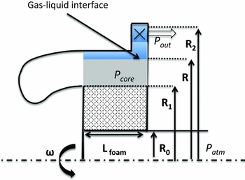
The PASS is shown on Figs 2 and 3. It is made of several vanes where a centrifugal separation occurs. In those two separation stages, the liquid is ejected on the external part of the prototype and is pressurised by radial vanes and a volute. Centrifugal forces generate a liquid film on the outer wall, and its thickness depends on the pressure at the liquid outlet and on the rotational speed. The air, still loaded with small oil droplets, flows through a metallic foam (a grade 45 Retimet foam from Meggit) that performs a third separation. The air then leaves through a dedicated outlet to the de-oiling measurement system.
Schematic of the PASS.

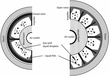
Front view schematic of the two different PASS designs: Lower radius and closed rotor on the left, higher radius and open rotor on the right.

Two different prototypes of the PASS have been studied. The baseline layout is the same for both but they differ by their size, the flow path of the mixture and the presence of a closed rotor (vanes surrounded by a rotating frame, no oil contact with the stator) or open rotor (small clearance between vanes and stator) for which there are important shear stresses between the rotating liquid film and the stator. The two designs are shown in Fig. 3. The larger radius increases centrifugal forces and the residential time (as it reduces the air speed and increases the de-oiling efficiency). The vanes are also designed differently (fewer non-radial vanes, back-swept and with a screw shape around the rotor). The high-diameter prototype has an axial length increased by 7%. The length and diameter of the tangential inlets are increased by 30% and 133%. The external radius (R 2) is only increased by 10%, but the centrifugation is performed at a location 33% higher as the metallic foam cross-section is increased by 60% and the gas outlet by 67%. The main components of the prototypes are made by 3D printing with a material containing 30% of bronze and 70% of stainless steel. The other parts are made out of aluminium and stainless steel.
Preliminary theoretical analysis, based on Bernoulli equation(Reference Steimes, Gruselle and Hendrick25), explained simply the behaviour of the liquid film created on the outer part of the prototype by the separated oil. It was developed using water/air prototypes that allowed a visual access to the PASS(Reference Gruselle, Steimes and Hendrick23). This theory is used to design the oil-air prototypes presented in Steimes et al(Reference Steimes, Gruselle and Hendrick24). Previous works(Reference Gruselle, Steimes and Hendrick23,Reference Gruselle37) indicate that the de-aeration efficiency of the PASS is dependent on the rotational speed, the back-pressure and the oil flow rate and temperature. Experiments reveal that a liquid film appears on the outer part of the prototype and that the back-pressure and the rotational speed are directly related to the thickness of this film. It plays an important role as the thicker it is, the better the de-aeration. Nevertheless, if its thickness increases too much, oil can freely leave through the air outlet and drastically decrease de-oiling efficiency (linked to R 0). A dimensionless model of this theory contains five variables: the relative pressure difference (pout − patm ), the rotational speed ω, the fluid density ρ l and the radii R and R 2. They are defined by three independent variables (mass, length and time), and are defined by two dimensionless coefficients: the pressure coefficient CP and the filling coefficient CR :
 $$\begin{equation}
C_P =\frac{p_{out}-p_{atm}}{\rho _{l} \omega ^2 R_2^2},
\end{equation}$$
 $$\begin{equation}
C_R = \frac{R}{R_2}
\end{equation}$$
The position of the liquid ring is related to as:
 $$\begin{equation}
C_P=1-\frac{1}{2} C_R^2
\end{equation}$$
Experiments(Reference Steimes, Gruselle and Hendrick25,Reference Steimes, Ruelle, Gruselle and Hendrick38) performed at the working conditions given in Table 1 validate the liquid film operating principle. The de-aeration efficiency is linked to CP , and thus to the liquid film position. The de-aeration performance of the high diameter and open rotor PASS is less efficient than the low diameter and closed rotor. The difference reaches 15% at CP =12%. As the radius difference between the two prototypes is taken into account in the pressure coefficient CP , the de-aeration efficiency is decreased by physical phenomena occurring in the impeller and in the volute. Indeed, the open impeller allows the gas and the liquid to flow between stator and rotor clearances (Fig. 3). This could lead to oil/air remixing.
PASS test bench working conditions

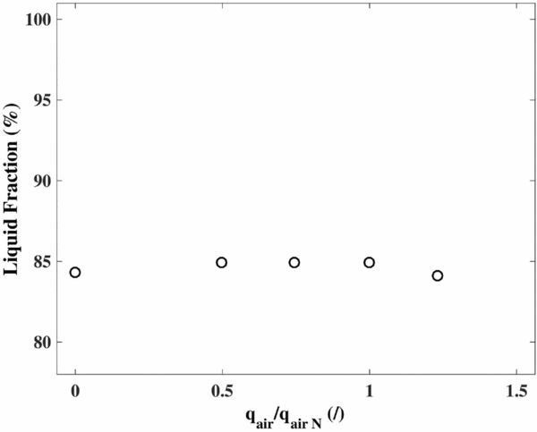
The aero-engine oil system must sustain a broad range of working conditions. Therefore, we studied the variation of the de-aeration efficiency with the air and oil flow rates and temperatures. Steimes et al(Reference Steimes, Gruselle and Hendrick24) point out that increasing the oil flow rate decreases the liquid fraction at constant Cp . A reduction of the liquid fraction of 10% can be observed by varying the flow rate from the design flow rate from 50% to 130%. This might be due to the higher number of separated droplets impacting the gas-liquid interface. In this case, air re-entrainment is more likely to occur. High oil flow rates also mean high drag forces on the air bubbles and the buoyancy effect has thus a lower impact on the separation. Steimes et al(Reference Steimes, Gruselle and Hendrick24) also indicate that an increase of the temperature for a constant Cp has an important impact until 0.63 the nominal testing temperature (TN ). Up to TN , the influence is limited for liquid fractions above 80%. This is explained by the important variation of lubrication oil viscosity between low and mid temperatures. The effect of the air flow rate (and thus of the air-oil ratios at the inlet of the prototype) is shown on Fig. 4. There is no significant difference due to the increase of the air flow rate. This is due to the low pressure drop generated in the prototype. With smaller prototype sizes, the pressure drop through the foam increases and pcore increases. This reduces the relative pressure that the liquid film has to produce. The film thickness decreases and more air is able to flow to the liquid outlet. The same effect was observed when artificially reducing the core pressure with a blower(Reference Gruselle37) to reduce its internal pressure. However, with careful prototype design this does not happen, as shown on Fig. 4.
Influence of the air flow rate on the de-aeration efficiency of the PASS with an open rotor, for
 $\dot{q}_{oil}=\dot{q}_{oil N}$
, T=0.31TN
and CP
= 14.5%.

The conclusions of these experimental studies demonstrate that it is preferable to design the PASS with a closed rotor. However, it is more difficult and costlier to manufacture. If the radius is decreased, the de-aeration efficiency increases as the CP is increased (with the smallest radius possible regarding de-oiling efficiency). The results illustrate that the hypotheses that lead to the liquid ring theory are inaccurate, as they do not take account of the variation of oil flow rate and temperature which are due to losses variation inside the PASS. Indeed, they are reduced at high temperature (frictional losses, disk friction losses, volute losses, etc.). This means that a smaller amount of energy produced by the rotating liquid film is lost before being converted in pressure in the volute. Therefore, the thickness of the liquid film necessary to produce the same outlet pressure is reduced as the head losses are reduced.
On the engine, pressure, rotational speed, oil flow rate and temperature are fixed by the flight phases. It is thus not possible to change the CP to adapt the de-aeration efficiency. The next section tries to model the behaviour of the PASS to take account of oil flow rate and temperature variations in order to predict in-flight de-aeration performance.
3.0 THEORETICAL AND DIMENSIONAL PERFORMANCE ESTIMATION
To predict in-flight performance, a new theoretical approach is required. Two different methods are used to take the losses into account: a physical analysis of the losses in the PASS (head and friction loss) and a dimensional analysis that takes into account the variation of the de-aeration efficiency with the working conditions.
3.1 Losses analysis
The PASS provides a certain amount of pressure that is absorbed by losses. For normal working conditions (low back-pressure), an important part of the losses is due to the losses in the volute. The liquid ring equation (Equation (3)) can be redefined by taking losses into account. For classical centrifugal pumps, the volute losses are proportional to the absolute velocity at the tip of the impeller:
 $$\begin{equation}
\Delta P_{volute} = \frac{1}{2} k_{volute} \ \rho _l V_2^2,
\end{equation}$$
with V 2 the absolute liquid velocity at the tip of the impeller and kvolute the head loss coefficient in the volute (between 0.02 and 0.03 for classical centrifugal pumps(Reference Nourbakhsh, Jaumotte, Hirsch and Parizi39)). Injecting these losses in the Bernoulli equation linking the total pressure in the outlet pipe (Pt out ) to the total pressure at the tip of the impeller (Pt 2) leads to:
 $$\begin{equation}
P_2^t - \Delta P_{volute} = P_{out}^t, \\
\end{equation}$$
 $$\begin{equation}
p_2 + \frac{1}{2} \rho _{l} \omega ^2 R_2^2 - \frac{1}{2} k_{volute} \rho _{l} \omega ^2 R_2^2 = p_{out} + \frac{1}{2} \rho _{l} v_{out}^2,
\end{equation}$$
 $$\begin{equation}
p_{out} = p_{atm} + \rho _l \omega ^2 R_2^2 \left(1 - \frac{k_{volute}}{2} - \frac{1}{2} \frac{R^2}{R_2^2}\right)
\end{equation}$$
Under a dimensionless form, with the same parameters as defined in Equation (3) (CP and CR ), the liquid film theory taking account of the losses in the volute is defined as:
 $$\begin{equation}
C_P= 1 - \frac{k_{volute}}{2} - \frac{1}{2} C_R^2
\end{equation}$$
A new pressure coefficient can also be defined so that the relation between the film thickness and the pressure coefficient is direct:
 $$\begin{equation}
C_{P}^{losses} = C_P + \frac{k_{volute}}{2},\\
\end{equation}$$
 $$\begin{equation}
C_{P}^{losses} = \frac{p_{out \ measured} + \frac{k_{volute}}{2} \rho _l \omega ^2 R_2^2- p_{atm}}{\rho _{l} \; \omega ^2 \; R_2^2}
\end{equation}$$
Finally, the liquid ring equations is thus governed by:
 $$\begin{equation}
C_P^{losses}= 1 - \frac{1}{2} C_R^2
\end{equation}$$
Equation (11) explains how the losses influence the position of the gas-liquid interface. For the same back-pressure and rotational speed, if the losses are important, Closses P increases and R is thus lower. The liquid film required to produce the same pressure at the liquid outlet of the PASS is thicker. The same methodology could be used to define the losses in the impeller. The losses in the impeller depend on the liquid film thickness, as it changes the cross-section where frictional losses appear. The experimental results reveal that the de-aeration efficiency is dependent on the pressure coefficient CP . As it was shown, CP is related to the liquid film thickness (to CR ). So, if Equation (11) takes into account every loss, it estimates a correct film thickness, and estimating the de-aeration efficiency is easier as every result is on a single curve defined as:
 $$\begin{equation}
\alpha _l = f(C_R) = f(1 - C_P^{losses})
\end{equation}$$
All the frictional losses vary with the temperature (and thus the viscosity of the oil), the flow rate and the rotational speed. According to the definition of Equation (4), kvolute varies with the working oil flow rate and temperature (the rotational speed is taken into account through ω). They are difficult to determine, especially for a prototype with unusual dimensions and made by 3D printing (unusual wall roughness). If kvolute could be defined for every working condition, Closses P would change in function of the working conditions. Considering a fixed back-pressure (pout ) and rotational speed (ω), this would change the estimated filling coefficient CR . It is thus complicated to characterise these losses with classical centrifugal pump theory(Reference Gülich40). Indeed, they are not linear: for the same back-pressure, when the size of the liquid film increases to compensate the losses due to an increase of the rotational speed, the friction losses of the film in the impeller also increase (thicker liquid film). For this study, it is more interesting to use a dimensional analysis to take into account the losses and to predict in-flight de-aeration performance.
3.2 Dimensional analysis
The experiments, at varying flow rates and temperatures, illustrated that the de-aeration efficiency is not only defined by the pressure coefficient CP but also depends on other parameters (flow rate, temperature, etc.) as predicted by the theoretical analysis of Equation (12). As the losses are difficult to compute, this section is focused on determining a correlation that predicts the de-aeration efficiency as a function of the working conditions.
3.2.1 Model definition
The Buckingham Pi theorem can be applied to analyse the de-aeration efficiency of the PASS. According to the experiments, the de-aeration efficiency is defined by the relative pressure increase pout
− patm
; the angular speed ω; the properties of the fluids ρ
l
, μ
l
, σ, ρ
g
, μ
g
, γ
g
; the dimension of the impeller R
2; and the liquid mass flow rate
 $\dot{m}_l$
. The air flow rate
 $\dot{m}_g$
does not impact the de-aeration efficiency significantly and is ignored (Fig. 4). The de-aeration efficiency is thus defined by 10 parameters that contain 3 independent variables. Seven dimensionless parameters are chosen:
-
1. The pressure coefficient (also called the Euler number),
$C_p=\frac{p_{out}-p_{atm}}{\rho _l \omega ^2 R_2^2}$
. It compares the pressure and the centrifugal effects. -
2. The Reynolds number Re ω usually defined for a turbo machine as
$Re_{\omega }=\frac{\rho _l \omega R_2^2}{\mu _l}$
. -
3. The Rateau’s flow coefficient defined as
$\delta _R=\frac{\dot{m}_l}{\rho _l \omega R_2^2}$
. It gives an indication of the flow direction (U and W). -
4. The Weber number:
$We_{\omega }=\frac{\rho _l \omega ^2 R_2^3}{\sigma }$
. It compares the centrifugal forces to the surface tension. It indicates if the two phases are highly mixed. -
5. The ratio of gas and liquid densities
$\Pi _{\rho }=\frac{\rho _l}{\rho _g}$
. -
6. The ratio of gas and liquid viscosities
$\Pi _{\mu }=\frac{\mu _l}{\mu _g}$
. -
7. The heat capacity of the air γ g .


The de-aeration efficiency can be expressed in function of these seven dimensionless numbers:
 $$\begin{equation}
\alpha _l=f(C_P, Re_{\omega }, We_{\omega }, \delta _R, \Pi _{rho}, \Pi _{\mu }, \gamma _g)
\end{equation}$$
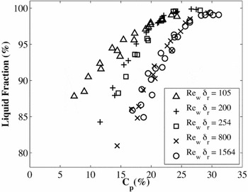
The experiments showed that the de-aeration efficiency is almost independent of the gas properties ρ g , μ g and γ g . The Weber number also plays a limited role. According to the loss analysis, it can be expected that the liquid fraction varies with Re ω (which is linked to kvolute ) and δ R (which is linked to the losses in the impeller and the volute due to the flow rate). Figure 5 shows the experimental results from Steimes et al(Reference Steimes, Gruselle and Hendrick24) plotted in function of CP for different working conditions corresponding to different values of the product Re ωδ R .
Experimental results expressed in function of Re ωδ r in function of the pressure coefficient.

The slope of the curves depends on Re ωδ R . The liquid fraction in the outlet pipe of the PASS is thus modelled as:
 $$\begin{equation}
\alpha _l = X C_P^Y, \\
\end{equation}$$
 $$\begin{equation}
X = 7.1081 \ln \left(Re_\omega \delta _R\right)+89.3,\\
\end{equation}$$
 $$\begin{equation}
Y = 0.053 \ln \left(Re_\omega \delta _R\right)-0.1082
\end{equation}$$
The difference with Equation (12) comes from the variation of X and Y with the working conditions. This allows to estimate the de-aeration efficiency without a precise knowledge of the losses in the PASS. Therefore, this correlation can only be used for the open impeller rotor. The de-aeration efficiency of other rotor architectures could be estimated with Equation (14), but the parameters X and Y must be adapted.
3.2.2 Model validation
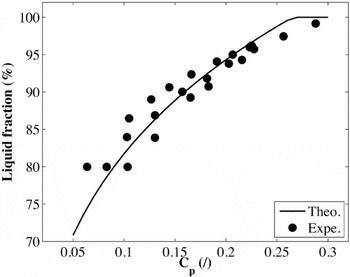
To validate the model, experimental results that were not used in the establishment of dimensional curves are compared to theoretical results. Figure 6 shows this comparison for an experiment in which both the oil flow rate and the temperature change at the same time. The results are in good agreement. Equation (14) can thus be used to predict the in-flight de-aeration performance of the PASS with an open impeller.
Comparison of the liquid fraction estimated by the model with the experimental results for
 $\dot{q}_l = \dot{q}_{l N}/2$
and Tl
= 0.63TN
.

4.0 EFFECT OF ENGINE CONFIGURATION ON PASS DESIGN AND PERFORMANCE
In traditional oil systems, sub-components are mechanically entrained, and their operation is linked to the engine rotational speed. The flight regime thus impacts the working conditions of the oil system. The inlet oil flow rate changes with the rotational speed of the feed pump. The oil temperature depends on the location of the heat exchanger and on the flight regime. The air flow rate depends on the compressor rotational speed, on the altitude and on the sealing technology. The oil pressure rise required to bring the oil back to the tank (pout − patm ) depends on the pressure losses in the pipes (i.e. oil temperature and flow rate, position of the oil tank and tank pressure). Four flight regimes are identified as critical in the PASS design(Reference Gruselle37):
-
1. Maximum Take-Off (MTO): At take-off, almost all engine power is required. Therefore, the rotational speed is the highest, and the feed pump provides a high oil flow rate. The air density at sea level and the high compressor rotational speed produce important bleed air pressure, and the air mass flow rate through the seals is high. The oil is heated up, but its temperature depends on the initial state of the engine and on the atmospheric temperature.
-
2. Cruise: The rotational speed is lower than at MTO. The air mass flow rate increases due to a higher compression in the engine inlet duct but is globally reduced due to the decrease density with flight altitude.
-
3. Cold start at ground idle: This flight regime considers the start of the engine in very cold weather, with a highly viscous oil at − 30°C. The rotational speed is lower than at cruise and MTO regimes. The air flow rate is also lower than in cruise as the pressure difference on the seal is lower.
-
4. Wind-milling: This regime corresponds to an in-flight engine shut-down scenario. The air velocity rotates (windmills) the engine at a very low speed. The mass flow rate is low as the density is low and there is almost no bleed pressure produced by the compressor. The oil temperature also decreases with the time.
For a fixed PASS design, these conditions affect the de-aeration efficiency by changing the back-pressure, the oil flow rate, the temperature and the rotational speed.
4.1 Engine and PASS configuration
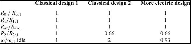
The radial size of the prototypes designed for the experimental study were mainly fixed to perform pumping in cold start and wind-milling conditions and to reduce the air velocity in the axial vanes to increase de-oiling efficiency(Reference Steimes, Gruselle and Hendrick24). Regarding flight regimes, the wind-milling operation due to a mechanical drive of the PASS on the engine shaft leads to very low rotational speed of the separator. Therefore, the radius needs to be chosen accordingly to ensure a sufficient pumping and returning of the oil back to the engine tank. This leads to a high power consumption and unadapted separator for most used flight regimes (MTO and cruise). If the sub-components are entrained by an electrical drive, the rotational speed can be de-coupled from the engine speed and thus ensure the vital operation of the lubrication system in case of wind milling at a constant rotational speed. The sub-component design conditions then change compared to a mechanical drive. From this analysis, it is clear that if alternative solutions are used to prevent the cold start and wind-milling conditions, the external impeller dimensions of the PASS and the rotational speed may be reduced, which leads to less weight and smaller footprint on the engine. Therefore, we study three different oil system and PASS design. Their characteristics are given in Table 2, and they are defined as:
-
1. Classical design 1: For the classical lubrication systems, subject to cold start and wind-milling working conditions, the rotational speed is fixed by the gear ratio with the high-pressure turbine through the gearbox. This ratio leads to a defined and fixed rotational speed in wind-milling conditions. It thus requires a minimum external impeller radius proportional to this ratio to ensure the pumping in wind-milling and the cold start conditions. The dimensions correspond to the prototype studied experimentally.
-
2. Classical design 2: The second design is installed in the same lubrication system as the first design but with another gear ratio. As the ratio is lower, the size of the impeller and the PASS footprint is reduced.
-
3. More electric design: This design considers future modifications to the oil system. First, the same constant rotational speed is imposed by the electric motor for every working conditions. Thus, it does not depend on the rotational speed of the engine, and it allows to not consider the wind-milling criterion in the PASS design. Secondly, it is stated that a small electrical heater is installed in the oil tank. This component heats up the oil in the tank before cold starts. This design also allows a more compact and lightweight PASS system on the engine.
Classical and More Electric prototype dimensions, compared to experimental prototype characteristics

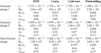
These three cases illustrate how the PASS would be integrated in a classical lubrication system architecture and in a more electric aircraft architecture. This design is implemented in a hypothetical future aero-engine. It is supposed to be installed in oil systems with ventless architecture and built around a hot tank configuration (heat exchanger in the feed line). The bearing chambers are equipped with brush seals. The operating conditions for this system are given in Table 3. This data is computed with the help of a code developed to model the operating conditions of the aero-engine lubrication system, which is explained in more detail in Adam and Hendrick(Reference Adam and Hendrick41).
Dimensional operating conditions affecting the de-aeration efficiency for future medium-to-small civil aero-engine in a ventless architecture

4.2 Performance estimation
Table 3 shows the dimensional numbers regulating the de-aeration efficiency of the PASS. C Rmax is the filling coefficient corresponding to the maximum allowable filling coefficient (linked to R 1 and R 2). Table 5 summarises the effect of the working conditions on the liquid fraction in the PASS oil outlet pipe. It shows that if CP decreases, the de-aeration efficiency decreases for the same value of the product Re ωδ r . If this product decreases, the de-aeration efficiency also increases. Table 4 shows the estimated de-aeration performance (with Equation (3)) in the three defined designs
Liquid fraction in the PASS outlet pipe for a future aero-engine working conditions (in %)

Regarding the de-aeration efficiency, the classical designs are more efficient in cold start and wind-milling conditions, as the film thickness is very high. They are inefficient in cruise and MTO regimes. The More Electric design present more interesting performances, as the liquid fraction reaches about 90% in MTO. It demonstrates the interest of the electrical drive entrainment. This design could also be further more improved if the electrical motor speeds was adjusted accordingly to the cruise phase (reduction of rotational speed).
The liquid fraction could be improved by increasing the pressure drop at the PASS outlet. This design could work in a cold tank configuration where the heat exchanger may be installed after the PASS. Computations performed with this conditions lead to an estimated CP = 14.39%. This provides a better de-aeration efficiency than the previous design as it would then reach 70% in cruise conditions. However, this would only work for the more electric design as the wind-milling and cold start conditions would lead to a large PASS radius.
4.3 Discussions on the MEA sub-components design
Alternative solutions can be designed to prevent cold start and wind-milling conditions. As discussed previously, a heater could be integrated into the oil tank to prevent cold starts and/or a check valve could also be installed on the air outlet of the PASS to prevent oil leaks at cold start. An electrical propulsion allows to rotate the sub-component even when the engine is wind-milling. The previous analysis shows that the external impeller dimensions of the PASS and the rotational speed may then be reduced. This increases its de-aeration efficiency. It also reduces the tangential velocity and thus the volute viscous losses. A better surface roughness than the roughness of the 3D-printed prototypes will also reduce the viscous losses. Therefore, the liquid film may be thinner and thus the de-aeration efficiency may be lower than predicted. The experiments reveal that the pumping efficiency is also increased by lowering the rotational speed. Reducing the external radius will lower the tangential velocity. This reduces the losses and the required pumping power.
However, this study highlights that the switch to more electric sub-components could help optimise the design of the engine sub-components for both newly developed components (as presented in this paper) or existing components(Reference Klingsporn21). Their size and weight might be reduced, while their performance would be increased and optimized for different flight conditions. This helps to reduce fuel consumption and emissions in aero-engines.
5.0 CONCLUSIONS
An integrated pump and separation system has been developed. This technology helps to improve performance and reliability of aero engine oil systems and allows to use ventless systems. This paper uses previous results to create new theoretical and dimensional models that helps to predict the pump and separation in-flight performance. This is necessary because future aircraft evolutions will affect these working conditions, and the technology needs to be designed accordingly. This model is used to illustrate the difference in design and performance that can occur from switching to more electric aircraft configurations compared to classical configurations. Especially, the difference between mechanical and electrical drive is discussed.
The new dimensional model allows to take account of varying flow rates and temperature and has been validated against experimental results. The working conditions of the engine have been defined for different flight regimes. Three scenarios have been envisaged: two with a mechanical entrainment and one with an electrical drive. The results illustrate that using an electrical drive with some modification of the engine oil systems would lead to the most interesting approach. This analysis illustrates that by switching to an electric entrainment, the footprint of the PASS on the engine is reduced by 34%, and de-aeration performance is improved by 55% at maximum take-off and 17% in cruise phase.
This conclusion joins other studies that highlights that switching to More Electric sub-components could help optimise the design of the engine for both newly developed components (as presented in this paper) or existing components. Their size and weight can be reduced, while their performance can be increased and optimised for different flight conditions. This helps to reduce fuel consumption and the emissions of aero-engines.
ACKNOWLEDGEMENTS
This research was supported by the Clean Sky Joint Technology Initiative consortium in the framework of the LubSEP project (JTI-CS-2010-3-SGO-02-029). The authors are also grateful to François Gruselle for his contribution to the first prototypes design and testing.