I. INTRODUCTION
Multiwalled carbon nanotubes (MWCNTs) have unique mechanical properties, including high elastic modulus (of the order of 1 TPa), tensile strength (approximately of the order of 150 GPa), and high aspect ratio.Reference Calvert1, Reference Pantano, Parks and Boyce2 Their extraordinary properties have enabled MWCNTs to be used as reinforcing agents in a copper (Cu) metal matrix to overcome the intrinsic high ductility of Cu and enhance its thermal and electrical conductivities.Reference Dong, Tu and Zhang3–Reference Guiderdoni, Estournès, Peigney, Weibel, Turq and Laurent6 Powder metallurgy-based processes such as isothermal sinteringReference Dong, Tu and Zhang3 and spark plasma sintering (SPS)Reference Kim, Cha and Hong4–Reference Guiderdoni, Estournès, Peigney, Weibel, Turq and Laurent6 have been developed for the consolidation of MWCNT-reinforced Cu composites after resolving the problematic agglomeration of MWCNTs in composites by ball milling of ultrasonicated mixtures.
Kinetic spraying (KS) is an emerging technology for metal matrix composite (MMC) consolidation.Reference Bakshi, Singh, McCartney, Seal and Agarwal7 Since conventional thermal spraying utilizes high thermal energy for melting and deposition of MMCs, phase transformation or destruction of the reinforcing agents occurs due to melting and oxidationReference Kang, Bae, Kim and Lee8 that caused deterioration in the properties of MMCs.Reference Laha, Kuchibhatla, Seal, Li and Agarwal9, Reference Kang, Bae, Kim and Lee10 In contrast, KS utilizes the kinetic energy of microsized particles that have been accelerated to supersonic velocities for consolidation without supplying significant heat energy. When the supersonic particles collide with a substrate, intensive plastic deformation occurs at an ultrahigh strain rate (1.0 × 10⁶ to 0.5 × 10⁹ /s).Reference Assadi, Gärtner, Stoltenhoff and Kreye11–Reference Bae, Xiong, Kumar, Kang and Lee13 Interfacial shear localization occurs such that instability in the interfacial plastic deformation induces adiabatic heating; during adiabatic heating, there is absence of heat transfer and the heat is retained at the local region where it is produced, causing thermal softening rather than melting during deposition,Reference Assadi, Gärtner, Stoltenhoff and Kreye11–Reference Kang, Bae and Lee15 due to which reason, the destruction of reinforcing agents is minimized.Reference Bakshi, Singh, McCartney, Seal and Agarwal7
The high interfacial strain deformation at an ultrahigh strain rate and strain gradient of Cu particles during KS results in metallurgical phenomena related to microstructural evolution such as interfacial grain refinement by continuous dynamic recrystallization (DRX),Reference Borchers, Gärtner, Stoltenhoff, Assadi and Kreye16–Reference King, Zahiri and Jahedi18 deformation twinning,Reference Kang, Bae and Lee15, Reference King, Zahiri and Jahedi18 and work hardening,Reference Kang, Park, Bae and Lee19–Reference Kang, Won, Bae, Ha and Lee21 which is also observed in severe plastic deformation processes.Reference Wang, Tao, Liu, Lu and Lu22, Reference Etter, Baudin, Rey and Pendle23 The bimodal microstructure of a KS Cu coating composed of a refined and work-hardened area strengthens the coating via grain boundary hardening and work hardening. In this study, we fabricated MWCNT-reinforced Cu nanocomposite powders by mechanical ball milling of well-dispersed mixtures (Cu particles + MWCNTs) and consolidated them by kinetic spraying. The hardness or strength of the KS nanocomposite coatings were compared with those of KS pure Cu coating and reported for MWCNT/Cu composites fabricated by SPS or sintering.Reference Dong, Tu and Zhang3–Reference Guiderdoni, Estournès, Peigney, Weibel, Turq and Laurent6 Based on microstructural and physical metallurgical analyses, the strengthening mechanisms of KS nanocomposite coatings are suggested.
II. MATERIALS
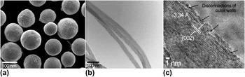
MWCNT/Cu nanocomposite powder was fabricated using a commercially pure Cu powder [size: −45.0 + 6.5 μm, purity: 99.99%; Fig. 1(a)] and MWCNTs [diameter: 20–50 nm; Fig. 1(b)]. They were blended at a MWCNT fraction of 0.5 and 1.0 wt%. The initial MWCNTs consisted of graphene sheets, forming a typical bamboo structure [Fig. 1(c)]. The interspacing of the walls was 3.34 Å. The bamboo structures were sound, however, the innate disconnections of outer-walls were observed [indicated by arrows in Fig. 1(c)].
Micrographs of initial materials: (a) SEM micrograph of the initial pure Cu powder. (b) TEM BF image of the initial MWCNTs. (c) HREM image of the outer walls of a MWCNT.

For heightening the intensity of effects of MWCNTs in the composites, interface of high quality between MWCNTs and Cu matrix, uniform dispersion of MWCNTs, and preservation of MWCNT structure are required. The MWCNT metal composite powder fabrication technologies that satisfy the requirements have been developed through blending, ultrasonication with dispersion agent and mechanical milling.Reference Kang, Bae, Kim and Lee8 In this study, the Cu and MWCNTs mixture was mechanically blended for 24 h, then, ultrasonicated for 2 h using ethanol as a dispersion agent. The blended mixtures were ball-milled mechanically. Zirconia balls (diameter: 5 mm) were used as ball milling media. The ball-to-mixtures ratio was 10:1. The ball milling was carried out for 10 h with rotation speed of 200 rpm.
III. METHODS
A. Kinetic spray consolidation
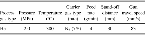
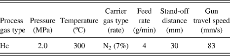
Spray coatings were achieved using a commercially available kinetic spraying system (KS; KINETIC 3000, CGT) with the tungsten carbide nozzle of convergent and divergent shape designed using the method of characteristics (MOC)-type mathematical analysis.Reference Schmidt, Gärtner and Kreye14 The details in kinetic spraying parameters are summarized in Table I. The process parameters were designed to accelerate the nanocomposite particles to supersonic velocities far higher than the critical velocity of Cu particles (560 m/s).Reference Assadi, Gärtner, Stoltenhoff and Kreye11–Reference Bae, Xiong, Kumar, Kang and Lee13 The equipment and kinetic spraying process have been described in detail elsewhere.Reference Kang, Yoon, Ji and Lee12, Reference Kang, Bae and Lee15, Reference Kang, Park, Bae and Lee19, Reference Kang, Won, Bae, Ha and Lee21, Reference Sundararajan, Phani, Jyothirmayi and Gundakaram24–Reference Wu, Zhou, Cui, Zheng and Zhang27 Polished Cu plates were used as substrates.
Kinetic spray parameters.
B. Analysis
The cross sections of the KS coatings were etched with a solution composed of 4 g CuSO4 + 20 mL HCl + 20 mL H2O after polishing, and observed using a field emission scanning electron microscope (FESEM; JSM-7500F, JEOL). For the TEM sampling of the coatings, the coatings were polished to be thin (approximately 100 μm) and were jet-polished electrolytically. Jet polished samples were ion-milled for 20 min to clearly observe the MWCNTs. The microstructures of the coatings were analyzed with a field emission transmission electron microscope (FETEM; Tecnai G2 F30 S-Twin, FEI). Selected area electron diffraction (SAED) patterns were taken. High-resolution electron transmission (HREM) images were analyzed and fast Fourier transformation (FFT) patterns were obtained by using analysis software (DigitalMicrograph, Gatan). The microhardness values of the coatings were measured utilizing a microhardness tester (HMV-2, Shimadzu). The surfaces of coatings were indented with a Vickers indenter under a load of 980.7 mN for 10 s.
IV. RESULTS AND DISCUSSION
A. Composite powder
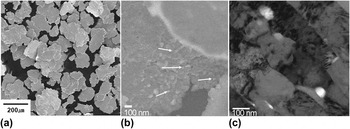
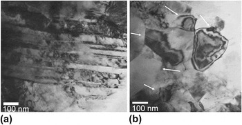
The fabricated MWCNT/Cu nanocomposite powder consisted of flake-shaped particles [Fig. 2(a)]. Since the MWCNTs were embedded inside the Cu matrix, they were not observed on the surface of the composite particles. But, excessive etching of the composite powders ionized Cu matrix, and revealed the MWCNTs on their surface as shown in Fig. 2(b). The MWCNTs were not agglomerated by the severe plastic deformation of mechanical milling. But, the severe deformation of the mechanical milling led to deformation band formation of Cu matrix [Fig. 2(c)]. The Cu grains were highly elongated (or strained), i.e., band structures were observed. The dislocation density was very high, however, grain refinement by DRX did not occur. The mean grain size of the Cu matrix was measured to be 232 nm by image analysis of several TEM bright (BF) images. The temperature of Cu matrix increased during continuous mechanical ball milling, therefore, the deformation twinning would not occur. DRX was not triggered due to inadequate strain and strain rate of mechanical ball milling.
Micrographs of composite powders: SEM micrographs of (a) the MWCNT/Cu nanocomposite powder and (b) the etched surface of a nanocomposite powder. (c) TEM BF image of nanocomposite powder.

B. Microstructural evolution
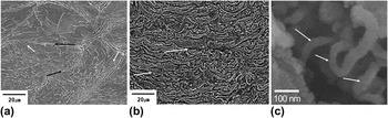
Deposition occurred through supersonic collisions of in-flight pure Cu and MWCNT/Cu nanocomposite powder during the KS process. In our previous study, the calculated mean in-flight velocity of pure spherical Cu powder was 788 m/s,Reference Kang, Bae and Lee15 which is remarkably higher than the critical velocity (560 m/s).Reference Assadi, Gärtner, Stoltenhoff and Kreye11–Reference Bae, Xiong, Kumar, Kang and Lee13 Since the large contact area with process gas increases the drag force of process gas, the in-flight velocity of the flake-type composite particles might be similar or slightly higher than that of spherical Cu particles at the same process parameter.Reference Wu, Zhou, Cui, Zheng and Zhang27 The deposition efficiencies, which is defined as mass ratio of deposited coating to that of the feedstock supplied, were 86% (0.0 wt%), 63% (0.5 wt%), and 42% (1.0 wt%), and this was inversely proportional to MWCNT fraction. The critical velocities of the composites increased with increase in strengthening rate.Reference Assadi, Gärtner, Stoltenhoff and Kreye11 Similar phenomenon was found in kinetic spraying of MWCNT/Al composites of our previous work.Reference Kang, Bae, Won and Lee26 Since the critical velocity is influenced by not only strength, but also contact area, and contact time, which are related to particle shape, it is not feasible to suggest the critical velocities of the MWCNT/Cu composites. Irrespective of the critical velocities, the bonding of kinetic spraying requires the interfacial adiabatic instability of the impacting powders at supersonic velocity.Reference Assadi, Gärtner, Stoltenhoff and Kreye11–Reference Bae, Xiong, Kumar, Kang and Lee13, Reference Kang, Won, Bae, Ha and Lee21 The supersonic collisions induced severe plastic deformation under adiabatic state changes at an ultrahigh strain rate (1.0 × 10⁶ to 0.5 × 10⁹/s),Reference Assadi, Gärtner, Stoltenhoff and Kreye11–Reference Bae, Xiong, Kumar, Kang and Lee13 and a significant strain gradient that developed from the impacting interface. The interfacial strain localization and strain gradients of KS metallic particles causes metallurgical phenomena such as metallic bonding,Reference Assadi, Gärtner, Stoltenhoff and Kreye11–Reference Bae, Xiong, Kumar, Kang and Lee13, Reference Kang, Won, Bae, Ha and Lee21 work hardening,Reference Kang, Bae and Lee15, Reference Kang, Park, Bae and Lee19–Reference Kang, Won, Bae, Ha and Lee21 continuous DRXReference Borchers, Gärtner, Stoltenhoff, Assadi and Kreye16–Reference King, Zahiri and Jahedi18, Reference Kang, Won, Bae, Ha and Lee21 and static recovery (SRV).Reference Kang, Bae and Lee15, Reference Borchers, Gärtner, Stoltenhoff and Kreye17, Reference Kang, Park, Bae and Lee19, Reference Kang, Won, Bae, Ha and Lee21 These metallurgical phenomena are related to the microstructural evolution of the KS metallic coating, which governs the mechanical properties or enhancement of the coating compared with the initial materials. The KS Cu coating had a highly strained microstructure that was typical [Fig. 3(a)] and that was also inhomogeneous due to the strain gradient of the impacting particle. At the interface, the grains were greatly elongated to a larger extent compared with grains located in the center, and twins developed [Fig. 3(a), white arrows]. The etched microstructure of the MWCNT/Cu nanocomposite coatings showed wavy structures with a flattened shape [Fig. 3(b)], and twins were not detected in the composite coating. The mean grain size of the Cu coatings was 3.7 μm, which is similar to that of the Cu powder (3.94 μm). Since melting-resolidification and significant grain growth hardly occurs during KS process, the grain size of the initial powder is preserved after KS.Reference Kang, Park, Bae and Lee19, Reference Kang, Won, Bae, Ha and Lee21 The microstructure of the composite coating was influenced by the initial powder shape and plastic deformation during the collision. The embedded MWCNTs are shown in Fig. 3(c). The interface strain of the KS Cu particles varies with position, and the strain at the central interface was approximately 1.0, whereas, the strain at the outer interface reached approximately 10.0.Reference Assadi, Gärtner, Stoltenhoff and Kreye11–Reference Bae, Xiong, Kumar, Kang and Lee13 Since the stacking fault energy (SFE) of Cu is approximately 78 mJ/m2, which is considered to be intermediate,Reference Humphreys and Hatherly28 the deformation mode of the Cu encompasses both dislocation slip and deformation twinning.Reference Meyers, Vöhringer and Lubarda29 The dominant deformation mode depends on strain rate and temperature. According to this model suggested by Meyers et al.,Reference Meyers, Vöhringer and Lubarda29 the critical strain rate for deformation twinning decreases as the strain rate increases and temperature decreases. The deformation twins were only positioned at the interface area [Fig. 3(a)]. TEM BF images of the representative interfacial microstructure of the KS Cu coating revealed deformation twinning [Fig. 4(a)], and DRX grains [Fig. 4(b)]. As the strain and strain rate increased from the center to the outer interface during an impact, the deformation mode transitioned from dislocation slip to deformation twinning. As the strain and strain rate decreased, the dislocation slip became the pronounced deformation mode. Indeed, over most of the deformed area, dislocation slip was the dominant deformation mode. A significant increase in dislocation density increases the strain energy and leads to dynamic restoration, i.e., DRX as continuous recrystallization. Due to the extremely short deformation time (approximately 50 ns) of the KS process, dynamic restoration may occur due to the geometric contribution of dislocations during deformation without any nucleation and growth. Figure 4(b) shows nanostructured-refined grains at the interface. Well-defined and equiaxed grains with a low dislocation density were formed at the localized interface area. Borchers et al.Reference Borchers, Gärtner, Stoltenhoff, Assadi and Kreye16 adopted a rotational DRX mechanism to explain the interfacial grain refinement of KS Cu coating. The details of rotational DRX in kinetic spraying are explained in our previous study.Reference Kang, Won, Bae, Ha and Lee21 In KS process, the deformation twinning and DRX in deposited Cu particles composed ofmicrometer-sized grains take place at localized area of impacting interface, therefore, these interfacial microstructure are not predominant throughout the coatings.Reference Kang, Bae and Lee15
SEM micrographs of (a) the etched cross section of the KS pure Cu coating (white and black arrows indicate twins and interparticle boundaries, respectively) and (b) the nanocomposite coating (white arrows indicate the interparticle boundaries). (c) SEM micrograph of MWCNTs in the nanocomposite coating (indicated by white arrows).

Interfacial microstructures of the KS pure Cu coating: TEM BF images of (a) deformation twinning and (b) DRX grains (indicated by white arrows).

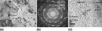
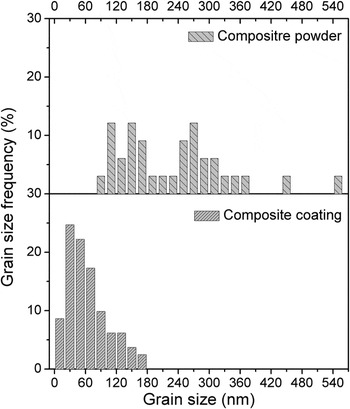
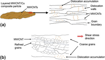
In the case of KS MWCNT/Cu nanocomposite coatings, the plastic flow of the Cu matrix was partially inhibited by the embedded MWCNTs. The stiff and strong MWCNT have a high aspect ratio and disperse uniformly. The forces produced by gliding dislocations was not sufficient to cut the stiff MWCNTs, thus, deformation twinning as observed at the pure Cu coating [Fig. 4(a)] did not develop. The inhibition of MWCNTs and the flake-shape of the nanocomposite powder restricted the strain and strain rate increments during KS. Figure 5(a) shows the microstructure of the composite coating. Large areas of the nanocomposite coatings underwent refinement, and were significantly different from the initial microstructure [Fig. 2(c)]. The grain size distributions of the composite coatings were measured by image analysis of ten TEM BF images. The mean grains size was 64 nm. As shown in Fig. 6, grain size distribution of the composite coating was significantly different from that of the composite powder, i.e., the grain size drastically decreased after deposition. In Fig. 5(a), nanocrystalline (<100 nm) or nanostructured (100–200 nm) refined grains were observed adjacent to the MWCNTs (white lines indicated by black arrows). The SAED pattern in Fig. 5(b) indicates the formation of a polycrystalline Cu structure. Closer to the MWCNTs, the sizes of refined grains were smaller. When the directional relationships of the MWCNTs with plastic stress are not vertical, dislocation movements, i.e., slip, intersection, and annihilation, can occur. Therefore, sufficient strains and strain rates for rotational DRX were generated, as observed in the KS Cu coating [Fig. 4(b)]. Figure 5(c) shows the embedded MWCNT. The interspacing of the basal plane in the MWCNT was preserved at 3.34 Å. The MWCNT was intimately associated with Cu matrix, showing no gaps. The initial microstructure of the nanocomposite powder [Fig. 2(c)] consists of elongated grains and high-density dislocations, which is a typical microstructure of deformed Cu before dynamic or static restoration. Since this deformed microstructure is thermodynamically metastable, the dynamic restoration or DRX may be more active than pure Cu [Fig. 4(b)]. Schematics of the strain induced grain refinement of the composite are shown in Fig. 7. The severe plastic deformation of mechanical ball milling resulted in deformation band formation of Cu matrix. The severe plastic deformation produced severe work hardening of high dislocation density, however, did not form refined structure by DRX. While the unstable structure of the composite powder underwent kinetic spraying, high strain and ultrahigh strain rate deformation formed DRX structure of Cu matrix. Even though the embedded MWCNTs also experienced the plastic deformation, thus, bending of some MWCNTs might occur. If the direction of shear stress that resulted from impact stress was parallel to the MWCNTs, the stress propagation was not severely inhibited by the MWCNTs and formation of DRX structure was facilitated.
Interfacial microstructure of the nanocomposite coating: (a) TEM BF image of a DRX subgrain cluster adjacent to embedded MWCNTs (black arrows indicate embedded MWCNTs). (b) SEAD pattern. (c) HREM image of the MWCNT embedded in the Cu matrix.

Grain size frequency of the composite powder and KS composite coating.

Schematic diagrams of mechanical reaction of MWCNTs with Cu during kinetic spraying: (a) Microstructure of MWCNT/Cu composite particle. (b) Microstructure evolution of kinetic sprayed composite coating [slightly magnified compared with (a)].

C. Strengthening mechanisms
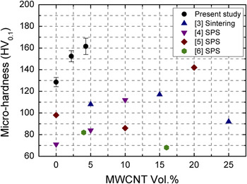
The microhardness values of the nanocomposite coatings are shown in Fig. 8. The microhardness of the KS pure Cu and nanocomposite coatings (0.5 and 1.0 wt%) were 129, 152, and 162 HV, respectively. The grain refinement by significant DRX and work hardening of the KS MWCNT/Cu nanocomposite coatings contributed to strengthening as well as the dispersion hardening of MWCNTs. The dislocation density was increased by plastic deformation during KS, leading to work hardening. This work hardening can be expressed as follows.Reference Botcharova, Freudenberger and Schultz30
![$$<
Microhardness values of nanocomposite coatings.

where, G is the shear modulus (45 GPa), b is Burgers vector (2.56 × 10⁻¹⁰ m), α is a constant (0.3), and ρdis is the dislocation density of the grain interior. The dislocation density of KS Cu was suggested to be ∼1016 /m2.Reference Borchers, Gärtner, Stoltenhoff and Kreye20 The calculated work hardening of KS nanocomposite coatings was 37.7 HV (345 MPa). The grain boundary hardening is expressed as the Hall–Petch relation as follows.Reference Hansen31
![$$<
where, kH (0.14 MPa m1/2) is a constant,Reference Hansen31 and d is the grain diameter. The mean grain diameter of KS pure Cu was measured as 3.7 μm. The grain refinement was mostly localized at the interface area; thus, strengthening by grain refinement was negligible. The grain boundary hardening of the KS pure Cu coating was 7.9 HV (73 MPa). The mean grain diameters of the refined and the unrefined areas of the nanocomposite coatings were 171 and 823 nm, respectively. The grain boundary hardening of the refined and the unrefined areas was 36.7 HV (33.7 MPa) and 16.9 HV (154 MPa), respectively. The grain boundary hardening of the nanocomposite coatings had the intermediate value in between refined and unrefined areas following a simple mixture rule. The contribution of embedded MWCNTs to strengthening is attributed to Orowan looping by MWCNTs. The stiff MWCNTs inhibit dislocation movement and harden intrinsic materials. The strengthening by MWCNTs can be expressed as follows.Reference George, Kashyap, Rahul and Yamdagni32
![$$<
where, A is a constant (0.093),Reference George, Kashyap, Rahul and Yamdagni32r is the volume equivalent radius of a MWCNT (159.3 nm),Reference George, Kashyap, Rahul and Yamdagni32r 0 is the core radius of a dislocation (3.5 nm),Reference George, Kashyap, Rahul and Yamdagni32 and λ is the distance between MWCNTs. The calculated values of the nanocomposite coatings were 41 HV (375 MPa) for MWCNT 0.5 wt% (2.2 vol%) and 51 HV (470 MPa) for MWCNT 1.0 wt% (4.4 vol%).
The calculated values for the strengthening contributions of the nanocomposite coatings through work, grain boundary, and dispersion hardening were reasonable and matched the experimental data. Taking into account the hardness of coarse grained Cu (∼70 HV, 742 MPa), the strengthening of the nanocomposite coatings was remarkable. Compared with MWCNT/Cu composites fabricated by SPS and sintering processes,Reference Dong, Tu and Zhang3–Reference Guiderdoni, Estournès, Peigney, Weibel, Turq and Laurent6 the microhardness of KS nanocomposite coatings was significantly higher (Fig. 8). The Strengthening efficiency of MWCNT reinforcement is defined as follows.Reference Kim, Cha and Hong4
![$$<
where, H C is hardness of a composite, H 0 is hardness of an intrinsic matrix, and V f is volume fraction of MWCNTs. We found a strengthening efficiency of 5.9–8.5. The MWCNT/Cu composite fabricated by SPS is in the ranges of 7.1–8.1,Reference Kim, Cha and Hong4 which is similar to our findings. Thus, the contribution of MWCNTs to strengthening of the composites is similar, irrespective of the consolidation process. The differences in hardness value (Fig. 4) were attributed to the microstructure of the Cu matrix. The SPS and sintering processes are expected to induce insignificant grain refinement during consolidation, whereas the KS process leads to supersonic collision induced strengthening by DRX and work hardening.
V. CONCLUSIONS
The supersonic collision induced strengthening of KS MWCNT/Cu nanocomposite coatings was investigated compared with a KS pure Cu coating. The embedded MWCNTs influenced plastic stress propagation during collision. Supersonic collision was associated with high strain deformation of the nanocomposite particles at ultrahigh strain rate. The ball-milled nanocomposite particles of the thermodynamically metastable structure underwent grain refinement by continuous DRX in a large area, while unrefined areas experienced work hardening. The grain refinement and work hardening by supersonic collision provided an advantage of strengthening in conjunction with Orowan looping of the embedded MWCNTs.
ACKNOWLEDGMENT
This work was supported by the National Research Foundation of Korea (NRF) grant funded by the Korea government (MEST) (No. 2012-0005448).