Introduction
Circularly polarized (CP) antennas play an important role in wireless communication systems and point-to-point links owing to their high tolerance to multi-path effects and polarization mismatching, so there is a high demand for CP antennas with properties such as a high gain, wideband, and a wide 3 dB axial ratio angle. CP antennas are designed by many methods. Among them, metasurfaces (MS) have proved to be efficient in CP generation and performance enhancement. Thus, a series of linear-to-circular polarization conversion MS-based antennas have been designed [Reference Li, Liu, Jia and Guo1–Reference Lin, Ge, Bird and Liu8]. In previously reported MS-based antennas, slot source antennas were usually used as feeders for their wideband to produce linearly polarized (LP) waves, which could be generated after passing through a polarization conversion metasurface (PCM), a polarization conversion to the CP mode [Reference Li, Liu, Jia and Guo1–Reference Zhu, Cheung, Chung and Yuk4]. Owing to their high gain property, several Fabry–Pérot (FP) resonant cavity antennas have been proposed in the design of CP antennas [Reference Xie, Wang, Li and Liang9–Reference Hussain, Jeong, Park and Kim15]. A PCM array consisting of two neighboring metal-coating-substrate unit cells, which act as a superstrate and feeding slot antenna, was combined in an FP-CP antenna [Reference Li, Liu, Jia and Guo1], realizing an enhanced gain and wideband CP radiation while maintaining a compact size. Another FP resonant cavity was formed by an all-metal cross-slot-etched frequency-selective surface and a nonstandard artificial magnetic conductor [Reference Muhammad, Sauleau, Le Coq and Legay16]. Fed by an obliquely placed patch, the antenna achieved high gain, wideband CP performance [Reference Liu and Lu17]. Other polarization-reconfigurable MS-based FP-CPs were also reported [Reference Ji, Qin, Jay Guo, Ding, Fu and Gong18]. However, most CP-FP antennas can only realize either a left-hand circular polarization (LHCP) or right-hand circular polarization (RHCP) state, while the dual-CP mode can be applied in a wider range for flexible controlled polarization according to requirements. Following this, several FP-CP antennas were proposed [Reference Naseri and Hum19–Reference Jiang, Zhang and Hong24]. As reported in related work, the dual-CP mode was realized in two ways: a dual-polarization source antenna acting as a feeder, and MSs, which convert to CP waves for LP signals at different frequencies, act as a superstrate. A polarization-reconfiguration source patch antenna, acting as a feeder, was proposed, where an MS-based FP antenna for LHCP, RHCP, and LP states can be realized by changing the polarization of the feeder [Reference Tran and Park25]. Through the design of different responses for LP waves, an MS superstrate can convert LP waves to different CP waves at different frequencies, resulting in a dual-CP FP resonant antenna [Reference Wang and Zhang26]. A dual-port slot source feeder was proposed to realize two polarization conversions when fed by different ports [Reference Huang, Wang, Li, Lin, Ge and Pu27]. The above techniques do not consider size reduction, high gain, and wideband, which pose a challenge to achieving satisfactory properties in a compact design.
The receiver–transmitter metasurface (RT-MS) suggests a possible FP cavity antenna with high reflectivity and low transmissivity, resulting in high gain [Reference Pan, Huang, Ma, Jiang and Luo28, Reference Clemente, Dussopt, Sauleau, Potier and Pouliguen29]. RT-MS generally consists of receiver and transmitter patches, along with a coupling layer. The incident wave is received by the bottom patch and coupled with the top patch [Reference Baena, Glybovski, del Risco, Slobozhanyuk and Belov30, Reference Diaby, Clemente, Pham, Sauleau and Dussopt31]. An off-center metal via a connecting receiver and transmitter was adopted to couple energy radiated by the slot antenna, resulting in a CP mode and achieving a high gain [Reference Xie, Wang, Li, Liang and Gao32]. However, it can only operate in a single polarization working band, while the aperture efficiency has a possible enhancement. To easily realize the phase and magnitude of the transmission, a slot-coupling approach was adopted [Reference Xie, Wang, Zong and Zou33], which achieved a high aperture efficiency, which gives us a reference for MS design with high-aperture efficiency. Slot-coupling occurs in dual-polarization antenna design [Reference Huang, Wang, Li, Lin, Ge and Pu27]. However, the gain-enhancement, resulting from the FP cavity, as well as the band improvement, has a possible increment, as shown through the design of a novel RT-MS and dual-feeder for the high gain property.
This study proposes a linear-to-circular polarized RT-MS of cross-slot coupling, with high gain, high aperture efficiency, and a dual-CP FP antenna. It has a rectangle patch as a receiver, a cross-slot coupling layer, and a corner-cut patch as a transmitter. The MS, with a transmission phase and magnitude-independent control, is designed to possess combined high reflectivity and the polarization conversion function, enabling the proposed antenna to achieve high gain and wide CP radiation. A dual-LP slot source antenna, acting as a feeder, produces LP waves, which can be operated independently. Thus, a high gain, high aperture efficiency, and a wide CP band FP resonant antenna are realized.
The remainder of this article is organized as follows. Section “Design process and analysis of proposed PCM” provides the design procedure and analysis of the proposed RT-PCM with high reflectivity and circular polarization conversion. Section “Analysis and design of proposed CP-FP antenna” presents the design and analysis of the FP-CP antenna. Section “Simulated and measured results” validates the design through simulated and measured results. We provide our conclusions in section “Conclusions”.
Design process and analysis of proposed PCM
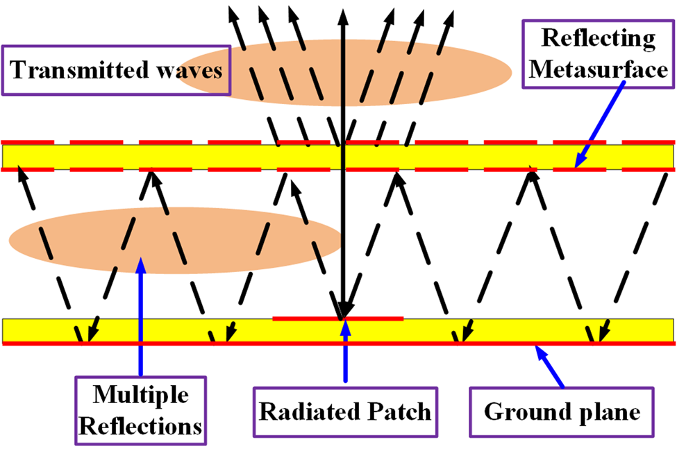
Generally, in a PCM-based antenna, an FP cavity is formed by a PCM and ground plane separated by a certain distance. As shown in Fig. 1, the electromagnetic wave illuminated by the radiator in the center of the cavity can be multiply reflected and transmitted into space.
Ray theory model of the Fabry–Pérot cavity antenna for increasing directivity.

To obtain the maximum directivity, reflected and re-reflected waves in the cavity must be transmitted in phase. Hence, as shown in (1), the reflection phases of the ground plane, ϕ GND, and those of PCM, ϕ PCM, should satisfy

Hence, a separation distance, hc, between them can be determined. Once the feeding antenna is designed, the center frequency and ϕ GND are basically fixed; that is, by optimizing ϕ PCM, a relatively smaller resonance mode, N, can be selected, and a low profile can be obtained.
The boresight directivity of the antenna can be calculated as in [Reference Wang and Zhang26]:

where R is the reflection magnitude of the PCM. Thus, a higher directivity is generated when R is larger, with the maximum directivity occurring when R is around 0.9 [Reference Xie, Wang, Zong and Zou33].
Based on the above analysis, when designing a dual CP-FP resonant antenna, three requirements should be met. The reflectivity of the proposed PCM must be high enough to achieve a high gain. The transmission coming from the cavity for coefficients T11 and T21 should have a phase difference of 90°, and be of equal or almost equal magnitude, to be transformed from LP to CP. Note that we define T11 as the transmission coefficient of the transfer of x-polarized waves to x-polarized waves when passing through PCM. So T21 represents the transfer of x-polarized waves to y-polarized waves when passing through PCM, where polarization conversion is realized. Then, as a source antenna feeding the PCM, the two orthogonal linear polarizations should be independently controlled, with high isolation; that is, the two S11s have no or less mutual effect. Hence, we use the following design process.
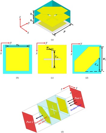
As shown in Fig. 2, the unit cell is constructed from two identical neighboring substrates (ɛr = 3.5, tanδ = 0.0014, h = 1.524 mm) of the size 5 mm × 5 mm, with three metal patches printed on them, consisting of a rectangle on the bottom, a cross-slot in the middle, and a conventional corner-cutting on the top. Figure 2(e) shows an HFSS model, where an incident wave can be received by the bottom patch of the receiver, coupled with the cross-slot to the radiated patch of the transmitter, where a CP wave radiates into space.
Geometry of RT-MS unit cell. Detail views of the unit cell for three layers: (a) transmitter patch; (b) etched cross-slot coupling metal plane; (c) receiver patch; (d) simulated model of the unit cell in HFSS.

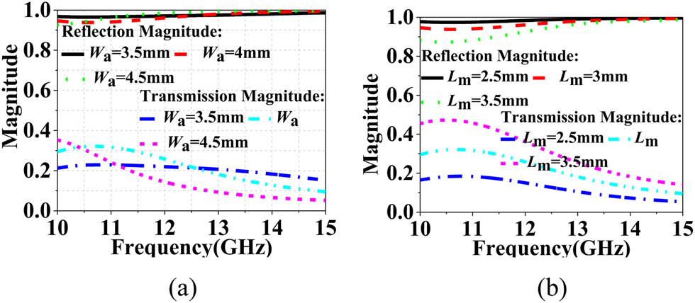
We investigated the lengths of the receiver patch, Wa, and cross-slot, Lm, as shown in Fig. 3. It can be seen in Fig. 3(a) that a larger size is preferred for lower reflectivity, which decreases as Wa increases from 3.5 to 4.5 mm. However, there is little influence on the transmission, which remains at about 0.95, ensuring a high gain with high reflectivity, R. A larger reflectivity is obtained as the length of the cross-slot decreases. We set Wa = 4 mm and Lm = 3 mm to achieve a reflectivity of around 0.95, which ensures a high gain.
Effect on S parameters at different lengths: (a) Wa; (b) Lm.

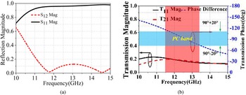
To introduce the cross-polarization component of transmission of the unit cell, the conventional technique of the corner cut is applied for the transmission of equal magnitude and a 90° difference. As plotted in Fig. 4(b), a wideband of almost equal magnitude across 10–15 GHz is obtained. Then, when Cm is equal to 2.5 mm, a pure 90° difference phase, indicating a phase of T21 being ahead 90° of that of T11, which leads to an LHCP wave coming out of the cavity, is achieved, with a band of ranging from 11.5 to 13.5 GHz. The band has a 0.95 higher reflectivity simultaneously, as shown in Fig. 4(a). Thus, a LP to CP transform across a band of 11.5–13.5 GHz is achieved, demonstrating that the transmitter can radiate CP waves.
Magnitudes and phases of transmission and reflection versus frequency for the optimum values granted to the unit cell: (a) magnitudes of reflection and transmission; (b) magnitude and phase difference for transmission.

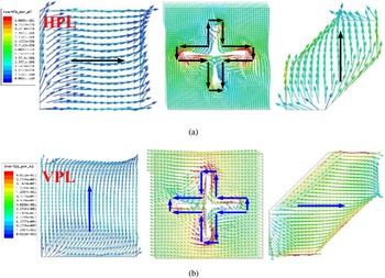
Figure 5 shows simulated E-field distributions for the horizontal and vertical linear polarization of the designed MS. When a horizontal linear polarization (HLP) wave is received, the coupling cross-slot can be motivated by the most E-field energy concentrated on it to obtain a radiation of 90° counterclockwise of the LHCP. This is different from the radiated wave to the vertical linear polarization (VLP) wave of 90° clockwise of RHCP, suggesting that the MS can perform in HPL and VPL CP modes.
Simulated E-field distributions for responses to different linearly polarized waves in three layers: (a) horizontal; (b) vertical.

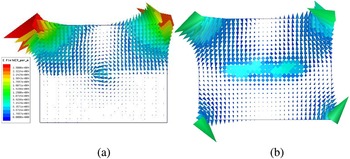
To explain the working principle, assuming illumination with a HLP wave, E-field distributions at the center plane of the cross-slot at 12.5 GHz in two orthogonal direction planes are given in Figs 6(a) and 6(b). The coupled electromagnetic wave passing through the cross-slot is roughly divided into two orthogonally distributed parts. The energy of the E-field is concentrated on the edge of the corner-cut radiated patch along the diagonals, with a 90° rotation. As displayed in Fig. 6(b), the E-field at another plane exhibits the same distributions, but the energy is obviously weak and can be ignored, demonstrating that the vertical branch of the cross-slot can only couple vertically polarized waves. This indicates that the cross-slot receives the wave from the receiver and is coupled with the transmitter with circular polarization.
Simulated E-field distributions at 12.5 GHz in two orthogonal planes: (a) xoz plane; (b) yoz plane.

Analysis and design of proposed CP-FP antenna
The proposed antenna is formed by a feeding antenna and PCM superstrate separated by an FP cavity. To guarantee a satisfactory gain property, a larger size is preferred to avoid wave diffraction at the edge of the cavity. However, owing to the small contribution in gain enhancement on the edge of the MS and less energy distributed on the cavity edge as the size increases, the aperture efficiency, that is,

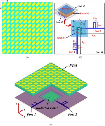
decreases, where G is the boreside gain, and A is the physical size of the aperture. Through numerical simulations, a tradeoff is made between gain and efficiency. Consequently, a 60 mm × 60 mm PCM array with a 12 × 12 unit cell is formed, as shown in Fig. 7.
Configuration of proposed dual-CP FP resonant antenna: (a) PCM; (b) sketch model of dual linear-polarization source feeding antenna and detailed views; (c) 3D sketch with dimensions Wv 1 = 4 mm, Wv 2 = 4.5 mm, Px = 15 mm, Psx = 20 mm, Lvx = 4.5 mm, Lvy = 5.5 mm, Lhx = 4.5 mm, Lhy = 6 mm, Lfhy = 28 mm, Lfvx = 31.5 mm, Wbhy = 3 mm, Lbhx = 7 mm, Lvs = 4 mm.

To achieve dual-LP waves in one source antenna, dual etched H-shaped slots in a metal plane is adopted in this design. Thus, a flexible switching on the two polarizations can be obtained. Figure 7(b) displays the configuration of the dual-polarized feeding antenna, which consists of three stacked metal substrates with a non-uniform size: Sub #1, Sub #2, and Sub #3. Sub #1 is made of Rogers RT (ɛr = 2.2, tanδ = 0.0014), with a thickness of 1.6 mm. Sub #2 and Sub #3 are 20 mm × 20 mm, and are made of Rogers TMM4 (ɛr = 4.4, tanδ = 0.0014), with a thickness of 0.8 and 1 mm, respectively. Note that there are no air gaps between them. To improve the impedance matching, which is worsened by the strong resonance of FP, shunt stubs are applied, whose impedance, through tuning, can match well with a wider band-pass. Stacked patches at the top of Sub #1 and Sub #2 are used to enhance the broadside gain of the antenna. Two 50 ohm SMAs (SubMiniature version A) connect to the edge of the substrate to feed the antenna. Here, note that two off-centered slots working on different S11 bands radiating HLP and VLP waves cause a slight difference in CP properties, although they are transmitted throughout the only RT-MS superstation. Particularly, the two non-uniform located slots affect the radiating LP wave's characteristics, such as the angle and distances to MSs, more than when hitting on MSs. Thus, the response of the polarization properties resulting from the angle and distances of the radiated waves is slightly different, making the results of LHCP and RHCP different. Then, we can conclude that slight variations occur in the coming results, but have little effect on the correctness of the design.
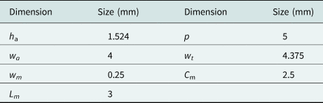
The PCM forms the top layer as a superstrate, separated from Sub #3 by an air gap, hC, to form an FP resonant cavity enabled by gain improvement. The separation height, hc, can be calculated by (1) and adjusted by simulations through HFSS to get an optimum value. In this design, considering its wideband and stable broadside radiation, a double H-shaped slot etched in the ground plane is unitized to an energy coupling for size reduction. Two orthogonal feed lines are adopted to feed the slots to excite two perpendicular linear polarization modes. Through numerous simulations, analyses, and comparisons, we obtained the optimal dimensions (Table 1).
Optimal dimensions of proposed RT-MS

Simulated and measured results
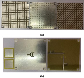
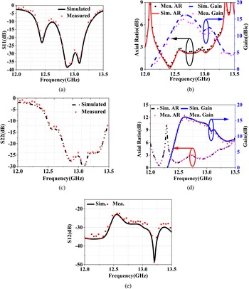
To validate the performance of the proposed antenna simulated by HFSS, we fabricated a prototype antenna, as displayed in Fig. 8, and measured it in an anechoic chamber using a far-field testing system. The measurements of the near-field data, S11, were completed by a vector network analyzer. Figures 9(a) and 9(c) show the plots of simulated and measured reflection coefficients for the two ports. It can be seen that an impedance bandwidth, determined by S11 < −10 dB, of 12.2–13.28 and 12.5–13.5 GHz, about 7.28 and 15.38%, respectively, is achieved for port1 and port2, respectively, which agrees well with the measured results except for some reasonable error. The antenna has the measured 3 dB axial ratios (ARs) for the two ports of 12.21–13.1 GHz (7.03%) and 12.35–13.1 GHz (5.89%), respectively, almost falling into the corresponding impedance bandwidths, as shown in Fig. 9(b). It also has minimum AR values of 0.3 and 1 dB, respectively, for port1 and port2, respectively, which validates the excellent CP characteristics.
Photograph of fabricated antenna: (a) PCM superstrate; (b) feeder.

Simulation and mensuration of proposed CP-FP antenna for port1 and port 2 under x and y incident waves. Results under x incident wave: (a) S11; (b) AR and bore-side gain. Results under y incident wave: (c) S22; (d) AR and bore-side gain; (e) S12.

The measured peak gain for LHCP and RHCP radiation can reach 16.3 and 15.97 dBic at 12.58 and 12.7 GHz, respectively, so there is little difference between them. Moreover, both have a gain that is 11 dBic higher than that of the feeding antenna. To our knowledge, this is the highest gain of dual-circularly polarization of such compact size, of 2.6λ 0 × 2.6λ 0, as depicted in Figs 9(b) and 9(d). Then, a slight difference occurs, mainly owing to measurement errors and machining accuracy, but it does not affect the design correctness. The isolation of the two ports within the impedance bandwidths is plotted in Fig. 9(e), and both have a gain of less than −25 dB.
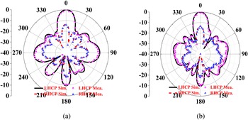
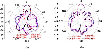
Another important radiation parameter, the radiation pattern, was investigated, as shown in Figs 10 and 11. Figures 10(a) and 10(b) show the LHCP wave radiation pattern at 13.5 GHz in the xoz and yoz plane, respectively, and Figs 11(a) and 11(b) show the RHCP wave radiation pattern in the xoz and yoz planes, which are apparently fed by port1 and port2, respectively. The figure confirms that the dual-polarization radiated wave into space passes through the designed PCM. From this, it can be seen that both side lode levels are less than −10 dB, and the cross-polarization levels are less than −15 dB. The measured results match well with the simulation results, suggesting excellent radiation performance.
Simulated and measured radiation pattern at 12.5 GHz fed by port1: (a) xoz plane; (b) yoz plane.

Simulated and measured radiation pattern at 12.7 GHz fed by port2: (a) xoz plane; (b) yoz plane.

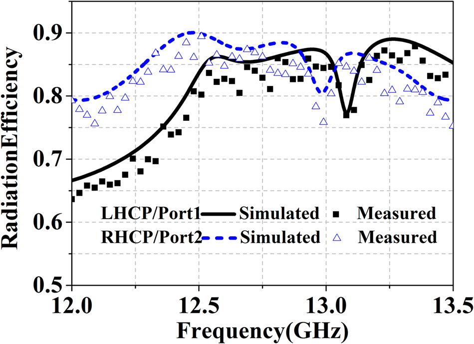
Figure 12 demonstrates that the radiation efficiency of the designed antenna, whether fed by port1 or port2, can be a maximum of more than 0.85 and a minimum of more than 0.8 in the working band, except there is a small degeneration of 0.05 in RHCP radiation fed by port2.
Simulated radiation efficiency for LHCP and RHCP radiation.
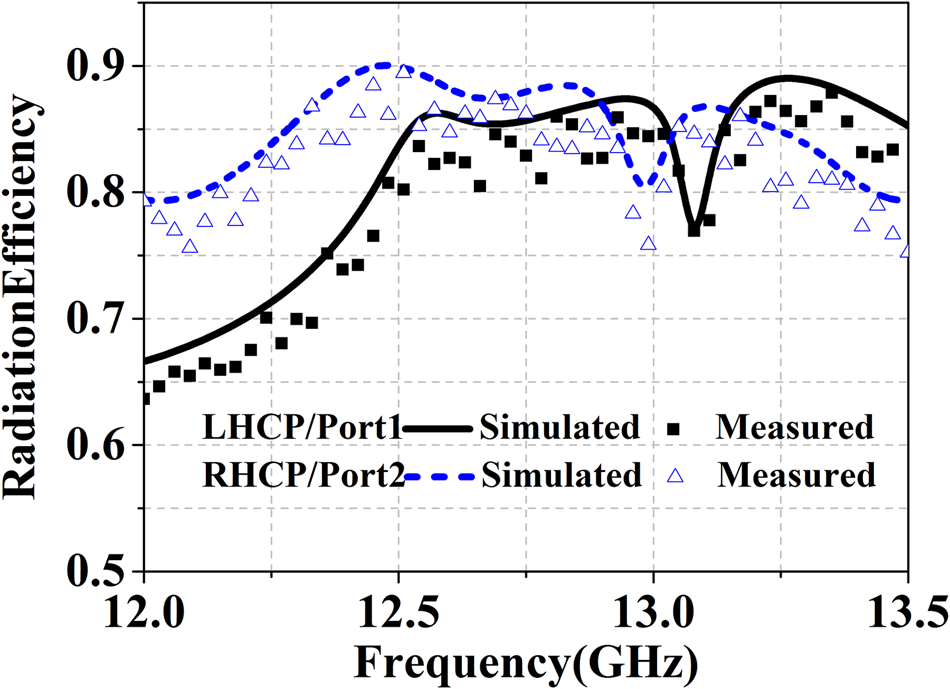
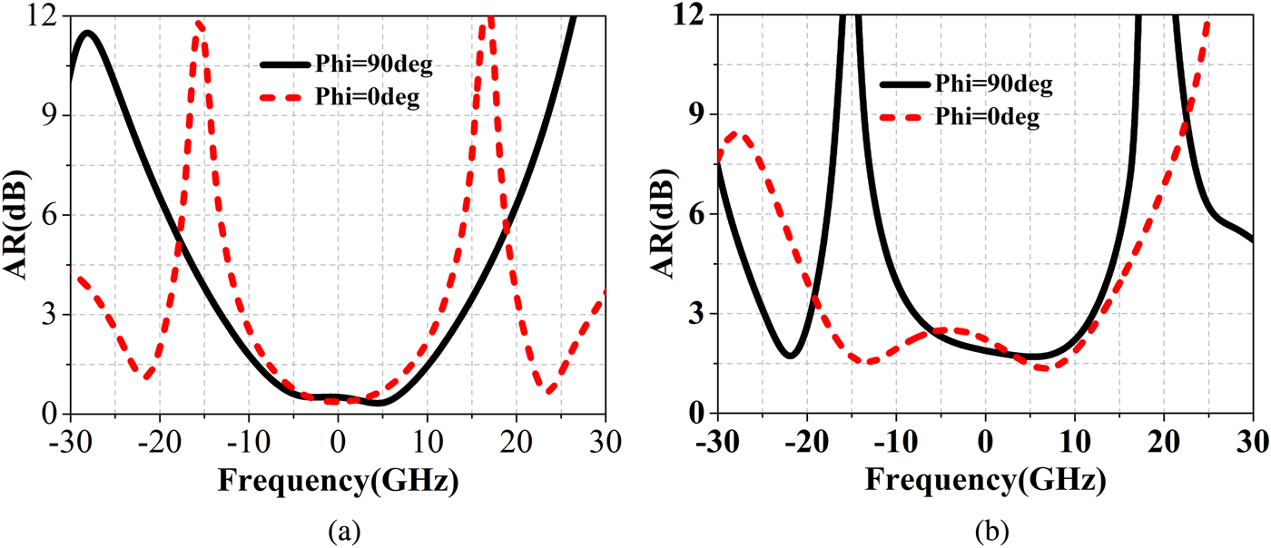
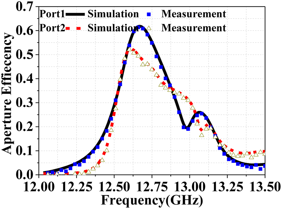
Figure 13 shows the AR value versus the angle in the xoz and yoz planes at 12.6 GHz. We can see that exceeding 20° of an AR value of lower than 3 dB in the main beam can be achieved, suggesting better CP radiation. The aperture efficiencies of the designed antenna for LHCP and RHCP radiation are displayed in Fig. 14, suggesting that maximum points of 63.2 and 54.6% occur at 12.58 and 12.7 GHz, respectively, indicating higher aperture efficiency compared with recent work.
Simulated ARs versus incident angle fed by port1 and port2, at 12.5 and 12.6 GHz, respectively.

Aperture efficiencies of proposed antenna for port1 and port2.

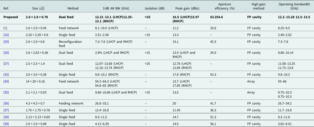
As listed in Table 2, compared with recently reported FP-CP antennas, the designed antenna can realize high gain, wideband dual-CP radiation with a more compact size and a simpler structure. By adopting a double slot with a cross arrangement, the proposed antenna can achieve independently controlled radiation, making it more flexible and possible to realize a high gain than other reported antennas.
Performance comparison of the recently reported CP-FP antennas

Note: “–” represents null.
Conclusions
We have presented a RT-MS-based FP resonant antenna with dual-CP. The RT-MS consists of three metal substrates, a rectangular patch at the bottom, as a receiver; a coupling cross-slot in the middle; and a corner-cut patch at the top, as a transmitter. Owing to the high reflectivity and aperture efficiency generated by the cross-slot, and by adopting an independently controlled dual-LP source antenna as the feeder and 12 × 12 cells arranged RT-MS array as the superstrate, the antenna has been shown to achieve better results in the gain property, wideband, and wide 3 dB axial ratio than other similar FP antennas. The proposed antenna has been fabricated and measured, and has shown a reasonable agreement except for slight errors with simulations. The results verify the correctness of our design. For the working band falling into the X/Ku band, it has achieved a high gain. Thus, the proposed antenna can be applied to army and commercial communications and other high-sensitivity applications for polarization wireless communications systems.
 Zhiqiang Yuan was born in Jiangxi, China. He received the B.S. and M.S. degrees from Wuhan University of Technology, Wuhan, China, in 2005 and 2011, respectively. His research interests include wireless communication and network.