





Introduction
Increasing data rates are one of the main drivers for next-generation mobile communication. Meeting this demand requires an increase in absolute bandwidth for communication systems. Therefore, the operating frequency has to increase compared to current 5G communication. In the context of 6G, part of the D-Band from 151.5 up to  $164\,{GHz}$ is intended for broadband communication systems [1].
However, enhancing the operating frequency towards the D-Band brings modern monolithic microwave integrated circuit (MMIC) technologies closer to their maximum oscillation frequency  $f_{{max}}$, making signal generation increasingly inefficient. Therefore, subharmonic system architectures are a common approach to operate suitable components, typically the generation of the local oscillator (LO), at a fraction of the desired output frequency. Although this enhances efficiency, adjustments to the system architecture are necessary. While most components have to be changed only in their center frequency, the IQ modulator also changes on the architectural side.
Fundamental IQ modulators require a quadrature signal pair offering a phase shift of  $90^\circ$. For subharmonic IQ modulators with a subharmonic factor of
 $N$, this phase shift changes to
 $\frac{90^\circ}{N}$. In this work, we focus on a subharmonic factor of two, which requires a phase shift of
 $45^\circ$, as shown in [Reference Schoepfel, Braun and Pohl2]. Therein, a delaying transmission line is used to generate a
 $45^\circ$ phase shift as a proof of concept for a subharmonic IQ modulator. However, the phase shift along a transmission line of a given length is inversely proportional to the operating frequency, which restricts the covered bandwidth.
Besides the apparent approach to generate a phase shift through a delay, several works showcase how a phase shift can be realized by using arbitrary phase difference couplers [Reference Abdelmagid and Wang3–Reference Wu, Shen, Liu, Leung and Xue5]. While most of the published work is realized on a printed circuit board (PCB), [Reference Abdelmagid and Wang3, Reference Stadler, Romstadt, Yildirim, Welling, Aufinger and Pohl6, Reference Ji, Shen, Zeng, Feng and Che7] present the only work realized integrated on an MMIC. Thereby, the highest reported center frequency for the generation of a  $45^\circ$ phase shift, which is suitable for integrated circuits, is at
 $55.4\,{GHz}$. For completeness, [Reference Chia, Ang, Tan and Yao8] reports a realization at
 $300\,{GHz}$. However, it is waveguide-based and therefore unsuitable for MMIC integration.
In this work, we propose a novel method to generate a  $45^\circ$ phase shift inside the W-Band. Thanks to the subharmonic factor of two, this work enables broadband IQ modulation in D-Band applications. An earlier version of this paper was presented at EuMW 2025 and was published in its Proceedings [Reference Schoepfel, Braun, van Delden and Pohl9]. This work extends the paper by mathematically describing the presented method in the second section. In addition to the fundamental idea, the impact of amplitude and phase errors is incorporated into this theory. To verify our proposed concept and to approve the mathematical relations, simulations of the structure were performed and extended by a comparison to the theoretical results in the third section. For validation, the proposed concept is realized in a Silicon Germanium (SiGe) technology. The measured results and a comparison to simulation and to the state of the art are presented in the fourth section.
Theory
Generating a 45° phase shift
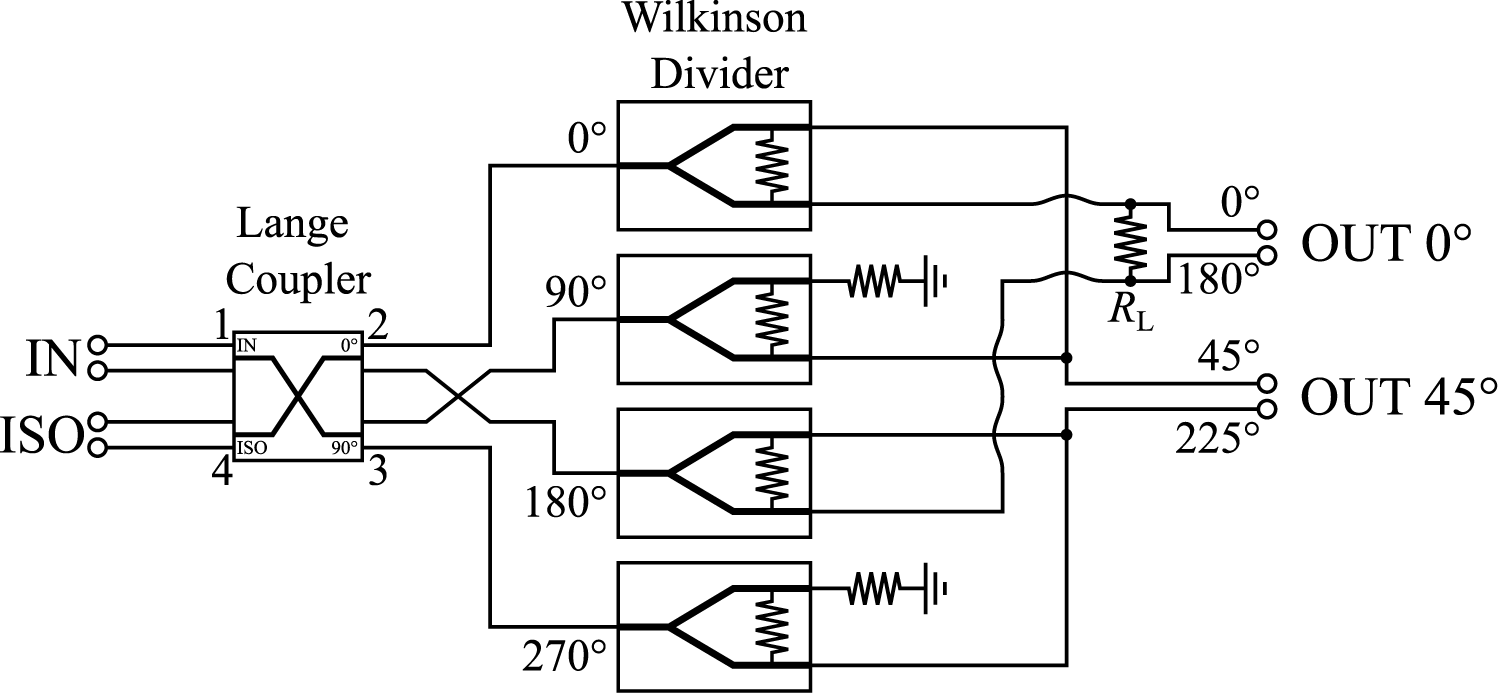
The underlying idea of our approach is to superpose phase states that are already available for fundamental IQ modulators, namely a quadrature consisting of  $90^\circ$ phase-shifted signals. For generating quadrature signals, a variety of approaches, from delaying transmission lines over polyphase filters to hybrid couplers, are well known in the literature. In our approach, we superpose quadrature signals to generate additional phase states. Figure 1 showcases our proposed method in a block diagram of the system architecture. It consists of two main components. A differential Lange Coupler is utilized to generate the quadrature signals. Wilkinson Dividers split the quadrature signals. A subsequent superposition of the signals results in a
 $45^\circ$ phase-shifted signal compared to the in-phase component.
System architecture to generate a balanced in-phase and  $45^\circ$ phase-shifted signal. The quadrature output signals of a Lange Coupler are superposed to generate a
 $45^\circ$ phase shift. Additionally, Wilkinson Dividers are used to split the in-phase output of the Lange Coupler, which also serves as the in-phase component for the proposed
 $45^\circ$ generator.

This approach can be described by an equation, which is based on addition theorems as described in (1). Therefore, a sine wave phase-shifted by  $45^\circ$ can be represented by the superposition of sine and cosine.
 \begin{equation}
\sin\left(x+\frac{\pi}{4}\right)=\sin(x) \cdot \cos\left(\frac{\pi}{4}\right)+\cos(x) \cdot \sin\left(\frac{\pi}{4}\right)
\end{equation}
 \begin{equation}
\sqrt{2}\cdot\sin\left(x+\frac{\pi}{4}\right)=\sin(x)+\cos(x)
\end{equation}
While the desired phase shift of  $\frac{\pi}{4}$ is achieved, the amplitude differs by a factor of
 $\sqrt{2}$ from the quadrature signals. As the quadrature signal’s in-phase component also serves as the in-phase component for the final architecture, the factor of
 $\sqrt{2}$ introduces a significant amplitude imbalance. A technique to compensate for this imbalance is described in the “Superposing network” section. Additionally, unlike in theory, the quadrature signals will differ in amplitude, and the phase shift between each other will not be exactly
 $90^\circ$.
Including differing amplitudes A and B in (2) reveals the impact on the resulting amplitude and phase.
 \begin{equation}
R\cdot\sin(x+\phi)=A\cdot\sin(x)+B\cdot\cos(x)
\end{equation}
 \begin{equation}
R=\sqrt{A^2+B^2}\qquad\qquad\phi=\tan^{-1}\left(\frac{B}{A}\right)
\end{equation}
The resulting amplitude  $R$ is always larger than the individual amplitudes
 $A$ and
 $B$. Additionally, the resulting phase
 $\phi$ depends on the ratio of
 $A$ and
 $B$, where a ratio of one results in the desired phase shift of
 $\frac{\pi}{4}$. Therefore, an amplitude imbalance between the sine and cosine impairs the desired phase shift.
Introducing not only an amplitude imbalance but also a phase error  $\phi_{{e,\frac{\pi}{4}}}$ extends (3) to the following equation:
 \begin{equation}
A\cdot\sin(x)+B\cdot\cos(x+\phi_{{e,\frac{\pi}{4}}})
\end{equation}
 \begin{equation}
= \underbrace{(A-B\cdot \sin({\phi_{{e,\frac{\pi}{4}}}}))}_{v}\cdot \sin(x)+\underbrace{(B\cdot\cos(\phi_{{e,\frac{\pi}{4}}}))}_{w}\cdot \cos(x)
\end{equation}
Using addition theorems, (6) illustrates that the resulting amplitudes of sine and cosine are dependent not only on the amplitudes of the initial signals  $A$ and
 $B$ but also on the phase error
 $\phi_{{e,\frac{\pi}{4}}}$. Therefore, the resulting amplitude
 $R$ and phase
 $\phi$ can be calculated according to (3) and (4).
 \begin{equation}
R=\sqrt{v^2+w^2}\qquad\qquad\phi=\tan^{-1}\left(\frac{w}{v}\right)
\end{equation}
As  $v$ and
 $w$ depend on amplitude imbalance and phase error, for
 $v=w$ the amplitude imbalance and phase error compensate for each other, resulting in
 $\phi=\frac{\pi}{4}$. Substituting
 $v$ and
 $w$ according to (6), the resulting equation can be rearranged to solve for the amplitude imbalance in (10).
 \begin{equation}
v=w
\end{equation}
 \begin{equation}
A-B\cdot \sin{(\phi_{{e,\frac{\pi}{4}}})} = B\cdot \cos{(\phi_{{e,\frac{\pi}{4}}})}
\end{equation}
 \begin{equation}
A_{{Imb}}=\frac{A}{B}=\cos{(\phi_{{e,\frac{\pi}{4}}})}+\sin{(\phi_{{e,\frac{\pi}{4}}})}
\end{equation}
Therefore, although the quadrature signals that are superposed exhibit imbalances in amplitude and phase, the resulting phase can still achieve the desired  $\frac{\pi}{4}$ as long as the amplitude imbalance fulfills (10).
IQ modulator requirements
Additional requirements regarding the  $45^\circ$ phase shift come from the theory of IQ modulators, which is the main application of this work. An important figure of merit for IQ modulators is the image rejection ratio (IRR), which can be expressed as follows:
 \begin{equation}
IRR=10\cdot \log_{10}{\left(\frac{1+A_{{Imb}}^2+2\cdot A_{{Imb}}\cdot \cos(\phi_{{e,\frac{\pi}{2}}})}{1+A_{{Imb}}^2-2\cdot A_{{Imb}}\cdot \cos(\phi_{{e,\frac{\pi}{2}}})}\right)}
\end{equation}
The IRR is dependent on the amplitude imbalance  $A_{{Imb}}$ and the phase error
 $\phi_{{e,\frac{\pi}{2}}}$. As equation (10) showcases, the phase and amplitude of the
 $45^\circ$ phase-shifted signal change depending on the imbalances of the superposed signals. To be able to optimize for a suitable set of amplitude imbalance and phase error, the ratio of both parameters for a given IRR can be calculated. Therefore,
 $A_{{Imb}}$ and
 $\phi_{{e,\frac{\pi}{2}}}$ can be described in dependence on the IRR as follows:
 \begin{equation}
A_{{Imb}}|_{\phi_{{e,\frac{\pi}{2}}}=0}=-\frac{1+10^{\frac{IRR}{10}}}{1-10^{\frac{IRR}{10}}}\pm\sqrt{\left(\frac{10^{\frac{IRR}{10}}+1}{10^{\frac{IRR}{10}}-1}\right)^2-1}
\end{equation}
 \begin{equation}
\phi_{{e,\frac{\pi}{2}}}|_{A_{{Imb}}=1}=\arccos{\left(\frac{10^{\frac{IRR}{10}}-1}{10^{\frac{IRR}{10}}+1}\right)}
\end{equation}
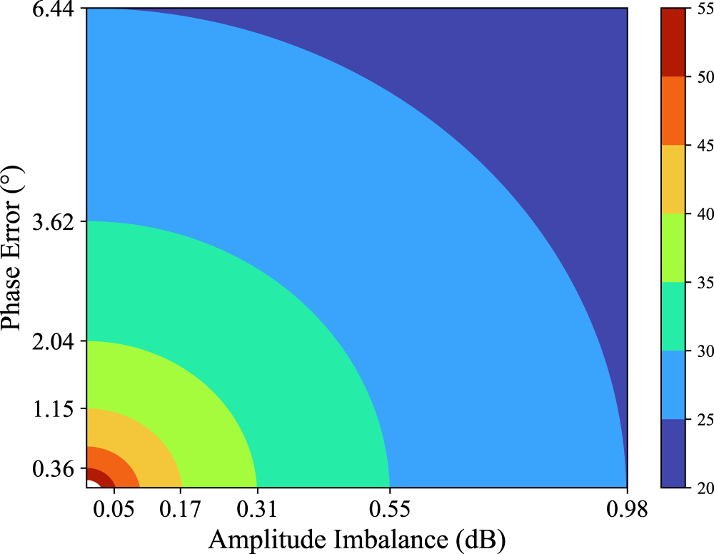
Scaled with (12) and (13), contours of constant IRR can be plotted as a function of the imbalances. Figure 2 showcases that the IRR maximizes for amplitude balance and zero phase error. Furthermore, for  $IRR \gt 20\,{dB}$ the ratio
 $r=\frac{\phi_{{e,\frac{\pi}{2}}}|_{A_{{Imb}}=1}}{A_{{Imb}}|_{\phi_{{e,\frac{\pi}{2}}}=0}}$ amounts to
 $\approx 6.6^\circ\,{dB^{-1}}$. This ratio gives a simple rule of thumb to identify the amplitude imbalance and phase error which result in a similar
 $IRR$. Especially for design scenarios where either phase error or amplitude imbalance is close to its optimum, this rule of thumb gives an approximate upper bound for the corresponding other error variable.
Contours of constant image rejection ratio. The axes are scaled to the same IRR, giving 6.6 as a rule-of-thumb ratio between phase error and amplitude imbalance.

System architecture
Lange Coupler
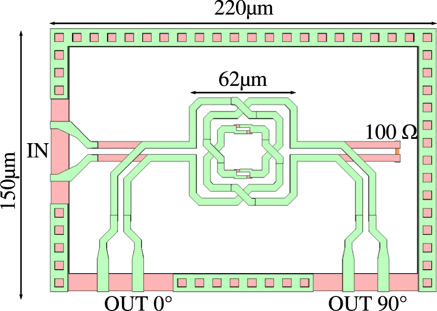
As shown in Figure 1, a Lange Coupler generates the superposed quadrature signals. The coupler is based on [Reference Schoepfel, Braun, Kueppers, Aufinger and Pohl10] and offers a broadband characteristic that reaches up to mmWave frequencies. A labeled depiction of the Lange Coupler’s layout as it is used in this work is presented in Figure 3.
Layout with the Lange Coupler’s most relevant geometry parameters.

In Figure 4, the simulated S-parameters are shown. Based on the difference between  $S_{21}$ and
 $S_{31}$ in magnitude, the amplitude imbalance is obtained and the difference in phase gives the resulting phase error, which is also shown in Figure 4. Inside the W-Band, the designed Lange Coupler provides an amplitude imbalance below
 $1\,{dB}$ and a phase error lower than
 $5^\circ$. Additionally, the coupler’s input port one and the isolated port four are matched better than
 $-10\,{dB}$. However, for the simulations, it is presumed that all ports are terminated with
 $100\,{\Omega}$. While this is the case for fundamental IQ modulator architectures, the assumption is not met for the architecture of this work. Unlike in fundamental architectures, here a superposing network following the Lange Coupler is required, which superposes its output signals to generate the
 $45^\circ$ phase shift. This superposing network loads the Lange Coupler unsymmetrically. The consequence and coping strategy for that will be discussed in the next section.
(a) Simulated S-parameters  $S_{21}$ and
 $S_{31}$ and the corresponding difference in phase of the utilized Lange Coupler. Additionally, simulated S-parameters for the Lange Coupler connected to Wilkinson Dividers, which are used in the superposing network, are shown. (b) Simulated amplitude imbalance and phase error of the utilized Lange Coupler.

Superposing network
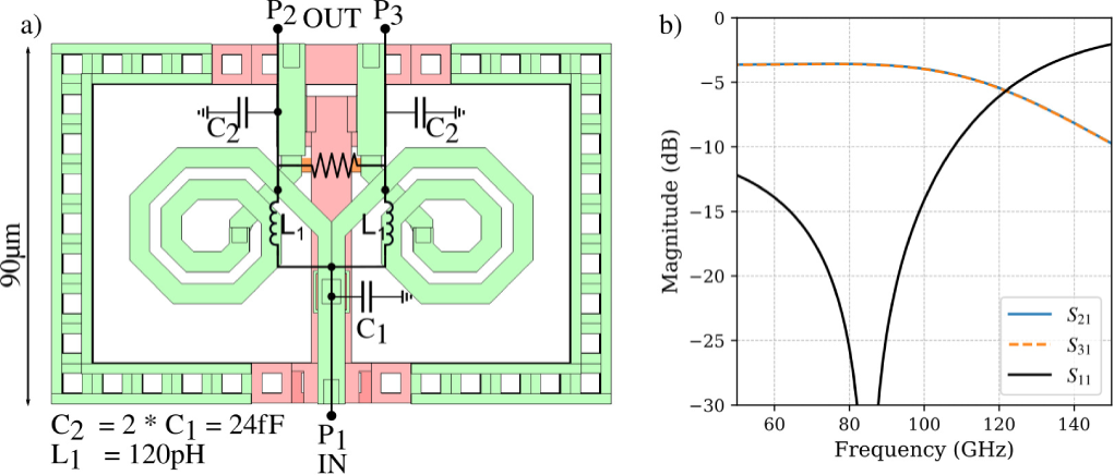
As the  $45^\circ$ phase shift is referenced to the Lange Coupler’s in-phase component, the in-phase component has to be split into two paths to simultaneously enable the superposition and the referencing. For splitting the signal, a Wilkinson Divider based on a lumped-element approach according to [Reference Pohl, Jaeschke and Aufinger11] is used, as it offers decent coverage of the W-Band and matches the Lange Coupler in terms of bandwidth. A layout with an overlaid schematic of the utilized Wilkinson Divider is shown in Figure 5. Additionally, the simulated S-parameters
 $S_{11}$,
 $S_{21}$,
 $S_{31}$ are depicted. However, the Wilkinson Divider introduces an additional phase shift for the in-phase component. This additional shift has to be compensated for the quadrature signal originating from port three of the Lange Coupler. Due to the Lange Coupler’s balanced architecture, the overall number of Wilkinson Dividers doubles to four. This results in eight output signals delivered by the four Wilkinson Dividers. While two of the signals form the reference path and four are superposed into the
 $45^\circ$ phase-shifted signal, two signals remain. These are terminated with
 $50\,{\Omega}$.
(a) Wilkinson Divider’s layout and superposed schematic with parameter values of the lumped elements. (b) Simulation results of the Wilkinson Divider.

Simulating the S-parameters  $S_{21}$ and
 $S_{31}$ for the Lange Coupler and for the Coupler in combination with the Wilkinson Dividers gives the amplitude imbalance and the phase error that have to be considered for the superposition. As shown in Figure 4, the individual Lange Coupler offers transmission losses of
 $\approx 3.5\,{dB}$. The difference between
 $S_{21}$ and
 $S_{31}$ that corresponds to the amplitude imbalance remains below
 $1\,{dB}$ between 70 and
 $140\,{GHz}$. Connected to the Wilkinson Dividers, transmission losses increase by
 $3\,{dB}$ in the range from 50 to
 $90\,{GHz}$ due to the signal split caused by the Wilkinson Divider. Up to
 $90\,{GHz}$, the characteristic is similar to the single Lange Coupler. However, above
 $90\,{GHz}$ the losses increase. This is caused by the transmission losses of the Wilkinson Divider, which increase above its center frequency of
 $80\,{GHz}$. However, the Wilkinson Divider’s impact on the amplitude imbalance is insignificant. Likewise, the phase difference between
 $S_{21}$ and
 $S_{31}$, from which the phase error can be extracted, changes marginally due to the Wilkinson Divider. In fact, the Wilkinson Dividers improve the phase characteristic, as the phase difference stays around
 $90^\circ$ up to
 $150\,{GHz}$, while the phase error increases for the single Lange Coupler. This improvement is caused by the Lange Coupler’s load impedance. Although the simulation of the single Lange Coupler assumes an ideal load of
 $100\,{\Omega}$, this load slightly changes due to the Wilkinson Divider.
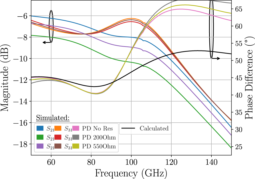
Based on the simulated imbalances, the resulting phase at the structure’s output can be calculated according to equations (6) and (7), as shown in Figure 6. Up to a frequency of  $90\,{GHz}$, the calculated characteristic of the resulting phase matches the simulation of the overall structure. For higher frequencies, the calculation and simulation show a discrepancy of up to
 $15^\circ$. This is due to connecting the Wilkinson Divider’s outputs to superpose the signals. Thereby, the impedances seen at the Lange Coupler’s outputs become unsymmetrical, resulting in differing impedances. The difference in impedance increases above
 $80\,{GHz}$, resulting in the observed deviation from the simulation.
S-parameters of the  $45^\circ$ generating structure. While the resulting phase difference and the
 $S_{31}$ are negligibly influenced by the resistor, the magnitude of
 $S_{21}$ can be chosen by adjusting the resistance. Furthermore, calculating the phase based on the simulations shows a similar course compared to the simulations, proving the equations.

In addition to changing the impedance seen by the Lange Coupler, the superposition causes an increased amplitude of the  $45^\circ$ phase-shifted signal compared to the in-phase component, resulting in a large amplitude imbalance according to (7). The most appealing solution to the imbalance is to use Wilkinson Dividers with an unequal power splitting ratio to compensate for the superposition [Reference Li, Wu and Wu12]. Replacing the two inner Wilkinson Dividers depicted in Figure 1 with unequal power split lumped element Wilkinson Dividers would balance the amplitudes at the structure’s output. However, this approach comes with disadvantages, making it unsuitable for the proposed concept. First and foremost, such an unequal divider is strongly sensitive to deviations in the individual lumped elements. Furthermore, there is no way to adjust the division ratio after production.
To allow an adjustment of the division ratio while reducing the amplitude imbalance, an additional resistor  $R_{{L}}$ is introduced into the in-phase output. Its impact on the performance of the
 $45^\circ$ generator has been verified through simulations. In addition to the phase characteristics, the magnitudes of
 $S_{21}$ and
 $S_{31}$ are shown in Figure 6 for increasing values of the resistor
 $R_{{L}}$. Although
 $R_{{L}}$ does not show a significant impact on
 $S_{31}$ and the phase difference,
 $S_{21}$ can be adjusted by choosing a suitable value for
 $R_{{L}}$. In simulation, a value of
 $550\,{\Omega}$ minimizes the amplitude imbalance at
 $80\,{GHz}$ and shows an imbalance below
 $1\,{dB}$ from 50 to
 $85\,{GHz}$. To enable the adjustment of
 $R_{{L}}$ after production, additional resistors that are short-circuited by fuses are placed in series with
 $R_{{L}}$. Cutting the fuses with a laser adds resistance to
 $R_{{L}}$.
Results
Measurements
To verify the proposed architecture in measurements, the  $45^\circ$ generator is realized in the
 $90\,{nm}$ SiGe BiCMOS Technology B12HFC with a
 $f_{T}$ of
 $300\,{GHz}$ and a
 $f_{{max}}$ of
 $530\,{GHz}$ [Reference Böck, Aufinger, Knapp, Mukherjee, Wohlmuth, Komenko, Rothenhäußer, Tschumakow and Stavrev13]. Four thin copper, one middle thick copper, two thick copper, and one aluminum layer are provided for wiring.
The available measurement equipment to characterize this structure consists of a four-port vector network analyzer, PNA-X, by Keysight. Equipped with four extender modules, this setup allows for four-port network analysis up to  $120\,{GHz}$, as shown in Figure 7. For calibration purposes, a GSGSG impedance standard substrate (ISS) is used. Therefore, the calibration’s reference plane is located at the probe tips. In addition to the proposed architecture, the single Lange Coupler and back-to-back structures for the pads, baluns, and connecting transmission lines have been manufactured.
Measurement setup of the manufactured  $45^\circ$ generator. A vector network analyzer is used to measure the structure’s S-parameters up to
 $120\,{GHz}$. An impedance standard substrate (ISS) is used for calibration.

A micrograph of the manufactured MMIC with an overlaid block diagram is shown in Figure 10. The MMIC consumes an area of  $0.92\,mm^2$, while only
 $0.45\,mm^2$ is occupied by the proposed
 $45^\circ$ generator. In addition to the core components, already explained in the previous section, four Marchand Baluns are placed in front of and behind the
 $45^\circ$ generator. These are necessary because of the balanced architecture of the proposed
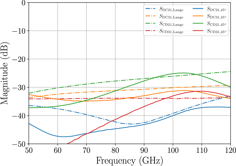
 $45^\circ$ generator, resulting in eight ports. The baluns reduce the eight ports to four. Thereby, the four-port vector network analyzer (VNA) allows for characterizing the manufactured MMIC. However, introducing baluns for port reduction introduces the disadvantage of galvanic isolation, preventing the VNA from exciting the common mode at the ports. Only the differential mode can be measured. As the desired mode of operation is differential, characterizing the differential mode is sufficient. To validate this claim, the mixed-mode S-parameters of the single Lange Coupler and of the complete
 $45\,^\circ$ generator were simulated and are shown in Figure 8. As all mixed-mode transmissions stay below
 $-25\,{dB}$, the differential mode is dominant in this work.
To measure the performance of the single Lange Coupler, the same Marchand Baluns are placed at all four balanced ports of the separate structure of the Lange Coupler. The strategy to de-embed baluns, pads, and connecting transmission lines is similar for the  $45^\circ$ generator as well as for the single Lange Coupler. The resulting four ports are characterized with the VNA to measure the S-parameters. Assuming symmetric fixtures from the VNA to the MMIC, an automatic fixture removal is used to extract the S-parameters of the solitary balun and pad with connecting transmission lines from the corresponding back-to-back structures. As explained in detail in [Reference Schoepfel, Braun, Kueppers, Aufinger and Pohl10], a three-port to two-port conversion had to be performed to de-embed the characterized fixtures from the four-port S-parameters of the overall structure.
Simulated mixed-mode S-parameters for the transmissions between input and output for the single Lange Coupler and the complete  $45\,^\circ$ generator. As all mixed-mode transmission coefficients stay below
 $-25\,{dB}$, it is valid to only measure the transmission of the differential mode.

In Figure 9, the measured S-parameters  $S_{21}$ and
 $S_{31}$ are depicted in magnitude and phase for the single Lange Coupler structure. In magnitude,
 $S_{21}$ and
 $S_{31}$ overlap in the frequency range from 75 to
 $100\,{GHz}$. Thereby, the amplitude imbalance in this frequency range is limited to a maximum of
 $2\,{dB}$. In terms of phase difference between
 $S_{21}$ and
 $S_{31}$, the ideal difference of
 $90^\circ$ is measured at a frequency of
 $83\,{GHz}$. From 50 to
 $120\,{GHz}$, an error
 $\le10^\circ$ can be observed. Comparing the measurement results to the simulations in Figure 4 confirms the overlapping characteristic of the transmission factors
 $S_{21}$ and
 $S_{31}$. Considering the phase difference, the measurements show an increased error compared to the simulation. This may be due to the fact that the Lange Coupler is loaded with an impedance differing from
 $100\,{\Omega}$ during measurement. However, all in all, the measurements demonstrate the Lange Coupler’s functionality.
Measured S-parameters  $S_{21}$ and
 $S_{31}$ in magnitude and phase for the single Lange Coupler. The measured phase difference shows a phase error of
 $\pm10^\circ$ from the ideal
 $90^\circ$. Furthermore, the magnitude of
 $S_{21}$ and
 $S_{31}$ overlap between 75 and
 $100\,{GHz}$, limiting the amplitude imbalance to
 $\leq2\,{dB}$ in this frequency range.

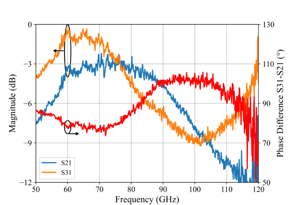
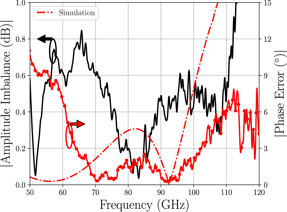
With the same measurement setup, the scattering parameters of the proposed  $45^\circ$ generator structure have also been measured. Based on the S-parameters, the phase error and the amplitude imbalance can be obtained. The results are shown in Figure 11. As shown in the red curve, a phase error below
 $6^\circ$ can be observed over more than the complete W-Band from 60 to
 $110\,{GHz}$. In terms of amplitude imbalance, less than
 $0.6\,{dB}$ is achieved within the W-Band. In the range of
 $80\,{GHz}$, the imbalance reduces to less than
 $0.1\,{dB}$. Around this frequency, the phase error offers its lowest values. Therefore, for the intended subharmonic mixer approach for D-Band frequencies around
 $160\,{GHz}$, the measured performance fits very well. Setting this performance in context with the measurement results of the single Lange Coupler shown in Figure 9, a drastically lower phase error can be observed in the frequency range from
 $70\,{GHz}$ to
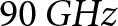 $90\,{GHz}$. As the Lange Coupler inside the proposed
 $45^\circ$ generator is followed by the Wilkinson Dividers, the Lange Coupler is decoupled from the balun, output pads, and the contacting probe. Thus, the load impedance seen by the Lange Coupler will be closer to
 $100\,{\Omega}$ compared to the structure of the single Lange Coupler.
Micrograph of the manufactured MMIC with an overlay of the corresponding block diagram. In addition to the core structure, Marchand Baluns are used to reduce the eight ports of the  $45^\circ$ generator to four. While a significant part of the chip area is reserved for pads and baluns, the area for the proposed structure amounts to
 $0.45\,mm^\circ$.

Phase error and amplitude imbalance based on the measured S-parameters of the proposed  $45^\circ$ generator structure. The dashed red line shows the simulated phase error.

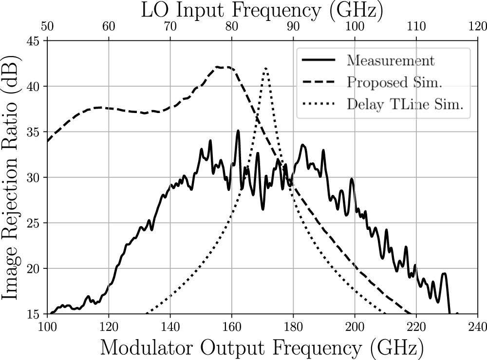
To evaluate the results of the  $45^\circ$ generator in terms of the intended subharmonic IQ mixer, the IRR can be calculated from the measured amplitude imbalance and phase error according to equation (11). Due to the subharmonic factor of two, the measured phase error, which is shown in Figure 11, has to be doubled to calculate the IRR, whereas the measured amplitude imbalance remains unaffected by this factor. The resulting IRR can be plotted over the operating frequency as shown in Figure 12. As amplitude imbalance and phase error show their minimum values in the frequency range from 70 to
 $95\,{GHz}$, the highest IRR of
 $\approx 30\,{dB}$ is achieved in this frequency range. In the context of subharmonic IQ modulators, a decent IRR could be realized in the range from 140 to
 $190\,{GHz}$. Compared to the simulation, the resulting IRR falls behind the simulation and is additionally shifted towards higher frequencies. To illustrate the superior performance of the proposed concept, the achievable IRR for a
 $\frac{\lambda}{8}$ delaying transmission line is additionally plotted. In terms of bandwidth, it becomes clear that the proposed approach achieves a drastically larger bandwidth. At the center frequency, the transmission line approach achieves a higher maximum IRR. However, this is only true for the utilized broadband design of the Lange Coupler. When designing the Lange Coupler for a smaller bandwidth, the overlap between
 $S_{21}$ and
 $S_{31}$ decreases, resulting in a lower amplitude imbalance and thereby higher IRR.
IRR calculated from the S-parameter measurement of the proposed  $45^\circ$ generator structure. For comparison, the simulated IRR is shown in the dashed line. To emphasize the large bandwidth for the shown approach, the IRR realizable with a delaying transmission line is shown in the dotted line.

State of the art
For a state-of-the-art comparison of the achieved results, the bandwidth guaranteeing a low amplitude imbalance or error in phase is used as the figure of merit in addition to the operating frequency. The most relevant publications regarding the generation of  $45^\circ$ phase are summarized in Table 1. Although most of the published work is realized on PCBs, several works have recently been reported showcasing integrated solutions on an MMIC [Reference Abdelmagid and Wang3, Reference Stadler, Romstadt, Yildirim, Welling, Aufinger and Pohl6, Reference Ji, Shen, Zeng, Feng and Che7]. While [Reference Abdelmagid and Wang3, Reference Ji, Shen, Zeng, Feng and Che7] offer a single-ended architecture, [Reference Stadler, Romstadt, Yildirim, Welling, Aufinger and Pohl6] is the only reference realizing an integrated balanced architecture. However, since a polyphase filter generates the phase states, [Reference Stadler, Romstadt, Yildirim, Welling, Aufinger and Pohl6] comes with significantly higher insertion losses of
 $\geq20\,dB$, necessitating subsequent amplification, and exhibits a high noise figure.
Comparison to state-of-the-art concepts for generating a  $45^\circ$ phase shift

Due to the lack of miniaturization, the realizations on PCBs reach center frequencies of up to  $31\,{GHz}$. When integrated on an MMIC, the maximum reached center frequency is drastically increased compared to the PCB realizations. The use of rectangular waveguides (RWGs) according to [Reference Chia, Ang, Tan and Yao8] enables further enhancement of the operating frequency. Although the RWG’s dimensions scale inversely proportional with the operating frequency, the waveguide-based approach is unsuitable for MMIC integration in the millimeter wave range. Therefore, the proposed
 $45^\circ$ phase generator achieves the highest operating frequency for integratable phase generators, extending the state of the art. Thanks to the broadband Lange Coupler, this work achieves the highest relative bandwidth in terms of phase error and amplitude imbalance. In addition, this work presents the only balanced solution apart from [Reference Stadler, Romstadt, Yildirim, Welling, Aufinger and Pohl6].
Conclusion
In conclusion, we proposed a broadband realization of a  $45^\circ$ phase shift. The concept is based on superposing a quadrature signal pair to generate a
 $45^\circ$ phase shift. By incorporating a broadband Lange Coupler, we achieve the highest relative bandwidth in terms of phase error and amplitude imbalance. We showcase the fundamental theory for our approach and prove it in simulation. Furthermore, we demonstrate operating frequencies inside the W-Band, extending the state of the art. Additionally, we present a balanced realization for the first time. This work is dedicated to subharmonic IQ modulators and therefore enables broadband LO generation.
Acknowledgements
The authors thank Infineon Technologies AG and its staff members for fabricating the chips.
Funding Statement
The authors gratefully acknowledge the German Federal Ministry of Research, Technology and Space (BMFTR) for partially funding this research in the course of 6GEM+ under grant number 16KIS2411. Furthermore, the work presented was carried out in the framework of the APECS Pilot Line of the Chips Joint Undertaking, funded by Horizon Europe (ID: 101183307) and Digital Europe (ID: 101182906) and national funding authorities of Austria, Belgium, Finland, France, Germany, Greece, Portugal, and Spain.
Competing interests
The author(s) declare none.

Jan Schoepfel (Member, IEEE) received the B.Sc. and M.Sc. degrees in electrical engineering and information technology and Dr.-Ing. degree from Ruhr University Bochum, Bochum, Germany, in 2014, 2016, and 2024, respectively. In 2025, he was with the Department of Integrated Circuits and Sensor Systems, Fraunhofer Institute for High Frequency Physics and Radar Techniques FHR, Wachtberg, Germany, before joining the Institute of Integrated Systems, Ruhr University Bochum, Bochum, Germany, in 2026. His research interests include the concepts and integrated circuits for radar sensors used in fully autonomous driving and for joint communication and sensing. Dr. Schöpfel was the co-recipient of the EuMIC 2021 Best Student Paper Award.

Tobias T. Braun (Member, IEEE) was born in Duesseldorf, Germany, in 1996. He received the B.Sc. and M.Sc. degrees in electrical engineering and information technology from TU Dortmund, Dortmund, Germany, in 2016 and 2019, respectively, and the Ph.D. degree in electrical engineering and information technology from Ruhr University Bochum, Bochum, Germany, in 2024. From 2019 to 2025, he was a Research Assistant with the Institute of Integrated Systems, Ruhr University Bochum, where he has since become the Institute’s Chief Engineer. His research interests include integrated circuit and system design for automotive applications, low-noise synthesizers for space observation, and nonlinear radar systems. Dr. Braun was the recipient of the EuMIC Young Engineer Prize from European Microwave Week in 2021, an honorable mention winner of the 3MT competition at the International Microwave Symposium 2022, and second-place winner of the Student Paper Competition at Radio & Wireless Week 2025.

Marcel van Delden (Member, IEEE) was born in Hattingen, Germany, in 1990. He received the B.Sc. and M.Sc. degrees and the Dr.-Ing. degree in electrical engineering from Ruhr University Bochum, Bochum, Germany, in 2012, 2015, and 2024, respectively. From 2013 to 2025, he was a Research Assistant with the Institute of Electronic Circuits, where he has since become an academic counselor. His current research interests include the design of integrated circuits and components for ultra-wideband frequency synthesis with the highest phase stability, as well as system concepts in the mm-wave and (sub)terahertz regime. He was a co-recipient of the EuMIC 2021 Best Student Paper Award and first-place winner of the 3MT competition at the International Microwave Symposium 2023.

Nils Pohl (Fellow, IEEE) received the Dipl.-Ing. and Dr.-Ing. degrees in electrical engineering from Ruhr University Bochum, Bochum, Germany, in 2005 and 2010, respectively. From 2006 to 2011, he was a Research Assistant and subsequently, from 2011, an Assistant Professor at Ruhr University Bochum. In 2013, he became the Head of the Department of mm-wave radar and high-frequency sensors at the Fraunhofer FHR, Wachtberg, Germany. In 2016, he became a Full Professor of Integrated Systems at Ruhr University Bochum. He has authored or coauthored more than 250 scientific papers and has issued several patents. His current research interests include ultra-wideband mm-wave radar, design and optimization of mm-wave integrated SiGe circuits and system concepts with frequencies up to 500 GHz and above, frequency synthesis, and antennas. Dr. Pohl is a member of VDE, ITG, EUMA, and URSI. He was the recipient of the IEEE MTT Outstanding Young Engineer Award in 2018, the Best Demo Award at RWW 2015, Best Student Paper Awards at RadarConf 2020, RWW 2021, and EuMIC 2021, and Best Paper Awards at EuMIC 2012, and of the AWPL in 2022.













 Open access

