Introduction
Magnesium (Mg) and its related alloys have gained considerable attention as an orthopedic implant material. They have evolved to be the material-of-choice owing to their distinctive properties such as (i) desirable degradability, (ii) high strength/weight ratio, (iii) favorable mechanical properties, and (iv) biocompatibility [Reference Staiger, Pietak, Huadmai and Dias1, Reference Witte2, Reference Shadanbaz and Dias3]. Most importantly, unlike other metallic implants, Mg alloys can potentially help eliminate stress-shielding issues as they possess an elastic modulus more comparable with that of cortical bone. Also, Mg-based alloys are nontoxic to the human body. In other words, the by-products of Mg dissolution are safe in the body. It is well known that Mg is an essential mineral component in the human body. Studies have reported significant therapeutic effects and biological advantages of Mg2+ ions [Reference Nabiyouni, Ren and Bhaduri4, Reference Sikder and Bhaduri5, Reference Tamimi, Le Nihouannen, Bassett, Ibasco, Gbureck, Knowles, Wright, Flynn, Komarova and Barralet6]. For example, it has been proven that Mg2+ ions stimulate initial osteogenesis and promote remodeling of fractured bones [Reference Witte, Kaese, Haferkamp, Switzer, Meyer-Lindenberg, Wirth and Windhagen7, Reference Ren, Sikder, Lin and Bhaduri8, Reference Touny, Sikder, Saleh and Bhaduri9, Reference Sikder, Bhaduri, Ong and Guda10]. In spite of all the advantages, the extremely high degradation rate of Mg and its alloys in the physiological environment is a significant limitation in its clinical applications. It can result in corrosion-induced mechanical failure and localized alkalization [Reference Staiger, Pietak, Huadmai and Dias1, Reference Hornberger, Virtanen and Boccaccini11]. The degradation process is related to the evolution of H2 gas, and this could cause severe problems in the surrounding tissues. One of the significant deleterious consequence is the obstruction of osteoblast attachment onto the implant surface. This issue affects the osseointegration (bone binding) capabilities of the implant, subsequently causing prosthetic failure [Reference Kraus, Fischerauer, Hanzi, Uggowitzer, Loffler and Weinberg12]. Hence, it is critical to regulate the degradation rate of Mg alloys to match the de novo bone formation rate without losing mechanical stability [Reference Staiger, Pietak, Huadmai and Dias1, Reference Shadanbaz and Dias3].
To improve the corrosion resistance of Mg alloys, two major strategies have been proposed: (i) tailor the Mg alloy microstructure or (ii) develop protective bioceramic polymer- or composite-based coatings [Reference Hornberger, Virtanen and Boccaccini11]. In contrast to microstructure alteration where the property of the bulk material is changed, surface modification techniques such as developing coatings have shown a more likely promising effect on the grounds of corrosion resistance. These coatings serve as the barrier layer to block the infiltration of attacking ions in the physiological medium onto the surface of the Mg alloy, thus effectively reducing the level of corrosion.
Out of all the biocompatible materials, calcium phosphate (CaP)–based products have received significant attention for decades and is still being explored [Reference Dorozhkin and Epple13, Reference Koju, Sikder, Gaihre and B Bhaduri14, Reference Sikder, Koju, Lin and Bhaduri15]. Hydroxyapatite [HA, Ca10(PO4)6(OH)2] has great chemical similarity to bone mineral and are highly biocompatible with good osseointegration capabilities [Reference Dorozhkin16]. As a result, various kinds of HA coatings have been synthesized on Mg alloys via different techniques, such as chemical precipitation [Reference Liu, Hu, Ding and Wang17, Reference Waterman, Pietak, Birbilis, Woodfield, Dias and Staiger18, Reference Cui, Beniash, Gawalt, Xu and Sfeir19, Reference Yang, Cui, Yin, Zhang, Zhang and Wang20, Reference Yanovska, Kuznetsov, Stanislavov, Danilchenko and Sukhodub21, Reference Cortes, Lopez and Mantovani22, Reference Cui, Yang, Jiao, Yin, Zhang and Lee23], electrodeposition [Reference Wang, Guan, Wang, Ren and Wang24, Reference Guan, Johnson, Cui, Zhao, Zhao, Li and Liu25, Reference Song, Shan and Han26], sol–gel [Reference Rojaee, Fathi and Raeissi27], and hydrothermal method [Reference Tomozawa and Hiromoto28, Reference Tomozawa, Hiromoto and Harada29]. Also, an interesting characteristic of HA is that various cations and anions can be doped into special sites in its lattice to render multifunctionality to the original materials or coatings. For instance, we recently developed silver (Ag+) ion–doped HA coatings which exhibited excellent antibacterial functionality against two infection-causing bacterial strains [Reference Sikder, Koju, Ren, Goel, Phares, Lin and Bhaduri30]. Similarly, fluorine-doped hydroxyapatite apatite (Ca10(PO4)6 (OH)2−xFx), where 0 < x < 2, fluorine-doped hydroxyapatite (FHA) and fluorapatite (Ca10(PO4)6F2) could be synthesized, respectively, by the partial and complete substitution of OH− by fluorine (F−). The incorporation of this specific halogen into the lattice was found to enhance the overall chemical stability of HA without undermining its biocompatibility and bioactivity [Reference Dhert, Klein, Jansen, Van der Velde, Vriesde, Rozing and De Groot31]. Nabiyouni et al. developed hexagonal fluorapatite nanotubes via microwave-assisted solution combustion and studied their morphological change after immersing the crystals in simulated body fluid (SBF) for 7 days. The nanotubes retained their hexagonal structure without much degradation [Reference Nabiyouni, Zhou, Luchini and Bhaduri32]. Li et al. prove that FHA coatings can stimulate the proliferation of human bone marrow stromal cells (hBMSCs) [Reference Li, Song, Zhang, Zhao, Zhang, Zhang, Cao, Fan and Tang33]. In another study, compared with pristine HA coatings, FHA coatings exhibited higher bonding strength to Ti alloy substrate and slower dissolution rate in the physiological environment [Reference Wang, Chao, Wan, Zhu and Yu34]. It is also worth mentioning that F− ions also showed distinct antibacterial effects [Reference Guha-Chowdhury, Clark and Sissons35]. Thus, it is hypothesized that FHA-based coatings possess favorable anticorrosive properties and also enhance the biological performances of Mg alloys. This is the reason we chose to synthesize FHA coatings with the help of microwaves in the present study.
It is well known that microwave irradiation coating technique can dramatically increase the chemical reaction rate and enhance the coating deposition kinetics [Reference Koju, Sikder, Ren, Zhou and Bhaduri36, Reference Bhaduri, Goel, Ren and Sikder37]. Our group has sustained research thrust in this coating technique, and we used it to coat multifunctional coatings on a diverse set of metallic (Ti6Al4V, AZ31 Mg) [Reference Zhou, Nabiyouni and Bhaduri38, Reference Ren, Zhou, Nabiyouni and Bhaduri39, Reference Ren, Babaie, Lin and Bhaduri40, Reference Sikder, Grice and Bhaduri41] and polymeric (poly-ether-ether-ketone (PEEK) implant prototypes [Reference Ren, Sikder, Lin and Bhaduri8, Reference Sikder, Grice, Lin, Goel and Bhaduri42]. Ren et al. fabricated the HA protective layer on AZ31 Mg alloys with the help of microwaves [Reference Ren, Zhou, Nabiyouni and Bhaduri39]. The coatings showed outstanding corrosion resistance property. Similarly, highly crystalline and thick biphasic magnesium phosphate (MgP) coatings were developed on AZ31 Mg within 10 min [Reference Ren, Babaie, Lin and Bhaduri40]. Considering the high efficiency of microwaves in developing coatings, we chose to develop the FHA layer with the same. However, in some cases, the as-deposited coatings might be porous in nature which might not be very beneficial in resisting substrate corrosion.
Recently, considerable attention has been focused in the development of organic–inorganic–based composite coatings [Reference Ren, Babaie and Bhaduri43]. These are mainly synthesized by combining a bioactive ceramic with a biocompatible polymer. Such coatings possess less intrinsic defects and have shown remarkable corrosion resistance properties and excellent durability [Reference Zheludkevich, Serra, Montemor, Salvado and Ferreira44]. So far, two distinct kinds of organic–inorganic composite coatings have been explored: (i) a single layer of coating with the inorganic bioactive nanoparticles uniformly dispersed in the biopolymer matrix and (ii) a bilayer coating with the biopolymer film being distinctly developed on the bioceramic for pore sealing [Reference Ren, Babaie and Bhaduri43].
Herein, the primary aim of this study was to develop a corrosion-resistant, protective bilayer coating on AZ31 Mg alloy and help in improving the implant’s in vitro or in vivo performances. We chose AZ31 Mg as our substrate as it is a preferred Mg alloy used in implant material fabrication. The coating comprised of an FHA bottom layer followed by a poly(lactic-acid) PLA over-layer. The FHA-coating was initially developed on an AZ31 Mg alloy as the bottom layer using the microwave-assisted coating technique. Subsequently, the biocompatible and biodegradable PLA coating was developed as an over-layer on top of the as-deposited FHA coating for sealing the pores. PLA is a Federal Drug Administration (FDA)–approved polymer and has shown favorable corrosion resistance property [Reference Xu and Yamamoto45]. The primary hypothesis is that both the monolayer FHA and hybrid FHA–PLA coatings will be able to protect the substrate surface from galvanic corrosion reactions and control the degradation behavior of AZ31 Mg alloys.
Results and discussion
Coating characterization
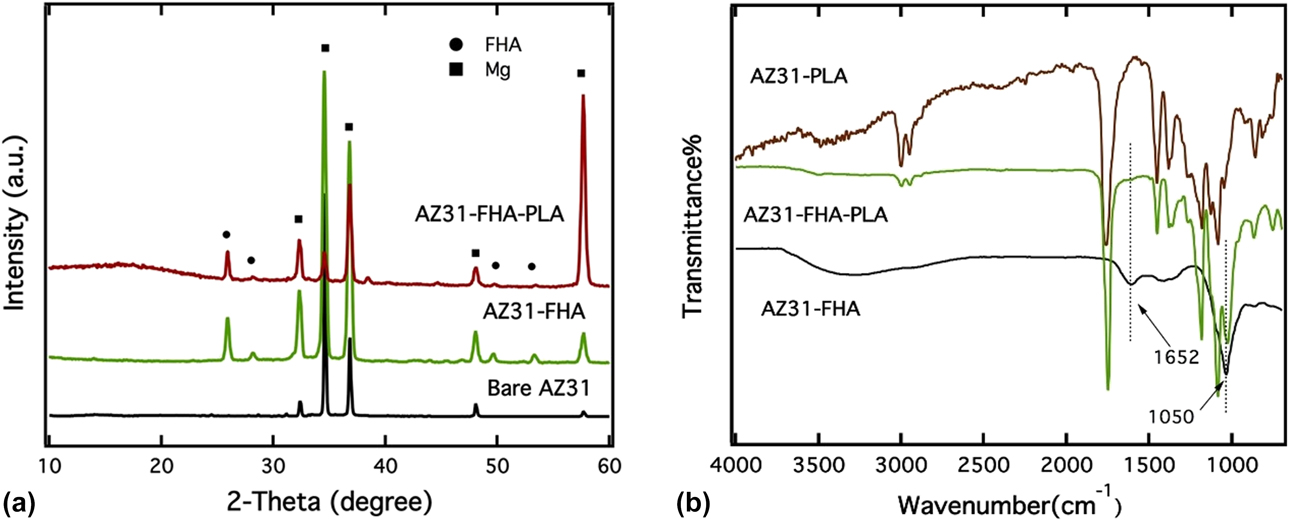
Figure 1(a) shows the X-ray diffraction patterns of bare AZ31 Mg substrates, only FHA and FHA/PLA–coated specimens. Most of the significant diffraction peaks corresponded to the Mg substrate. This indicates the low thickness of the as-deposited coatings. Apart from the prominent Mg peaks (PDF # 98-001-7795) from the substrate, diffraction peaks in the 2θ range of 25–30° and 50–55° were observed for specimens which underwent the microwave irradiation coating process. These peaks pertained to the FHA phase (PDF # 98-001-0335) indicating the successful formation of FHA coatings on AZ31 Mg alloys. However, apart from the FHA diffraction peak at around 2θ angle of 26°, the intensity was not high for the remaining ones. This result might be due to the poorly crystallized FHA layer on the AZ31 Mg substrate owing to the energy barrier in the microwave irradiation coating technique [Reference Ren, Zhou, Nabiyouni and Bhaduri39]. Furthermore, in the case of the FHA/PLA–coated sample, it was difficult to see the FHA diffraction peaks (2θ range 50–55°). The presence of the amorphous PLA coating made it difficult for the X-rays to penetrate through the polymer layer, and this resulted in either concealment or significant reduction in the intensity of the FHA diffraction peaks. The crystallographic analysis by MD Jade software (2010) indicated that FHA presents a similar hexagonal crystal structure to HA and belongs to the same P63/m space group of HA. However, the replacement of OH– by F– in the HA lattice led to the reduction in the a-axis dimension because of the difference in the anion size (parameters: a = b = 9.462 Å and c = 6.849 Å, α = β = 90°, γ = 120°) [Reference Ren46].
(a) XRD patterns of the AZ31 substrate, the FHA-coated, and the PLA/FHA-coated samples. (b) FTIR spectra of the PLA coating, the FHA coating, and the PLA/FHA composite coating.

Figure 1(b) shows the FTIR spectra of PLA, FHA, and FHA–PLA composite coatings on the AZ31 Mg substrate. The absorption peak centered at 1050 cm−1 attributed to the phosphate  $\left( {{\rm{PO}}_4^{3 - }} \right)$ band with asymmetric stretching ν3 mode [Reference Gadaleta, Paschalis, Betts, Mendelsohn and Boskey47]. The broad absorption peaks at 3300 cm−1 and 1652 cm−1 can be allocated to v 1 symmetric stretch and v 2 bend of structural water, respectively. It is interesting to note the presence of several absorption peaks in case of the PLA-coated specimen. These characteristic peaks are because of symmetric and asymmetric stretching of an ether group (C–O–C) and carbonyl (C=O) group in the PLA structure. On the contrary, very smooth FTIR plots were observed for the FHA/PLA- and FHA-coated specimens. Overall, the FTIR results were in well accordance with the XRD analysis [Reference Ren46].
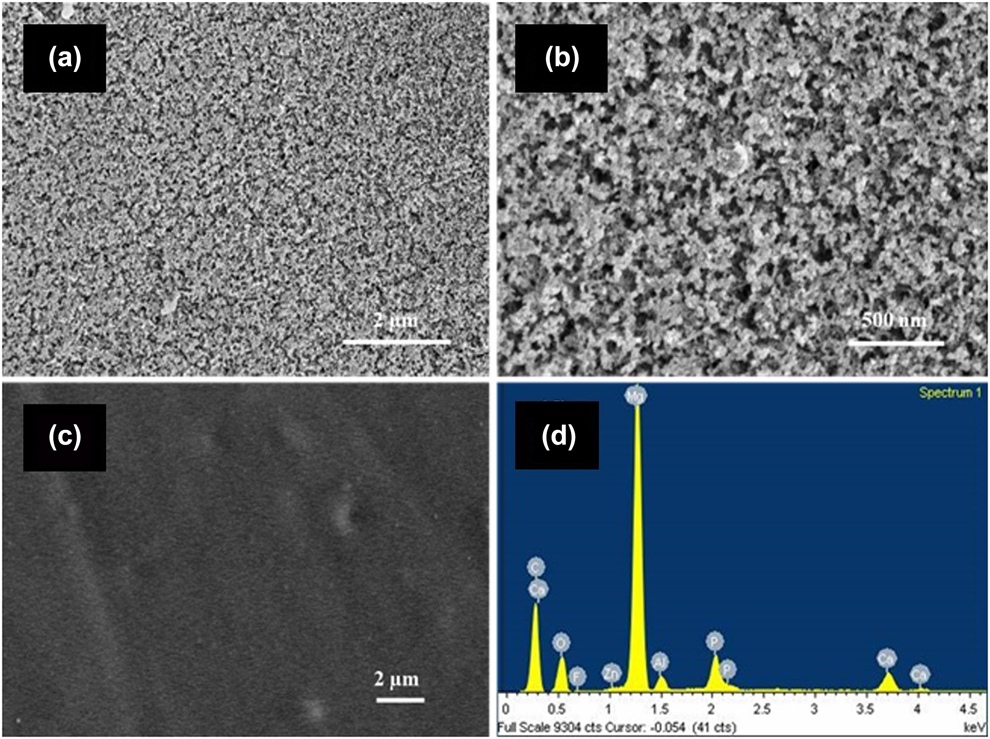
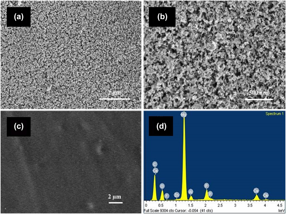
Figures 2(a)–2(d) presents the surface morphology and elemental compositions of FHA- and FHA/PLA–coated specimens. In both the kind of coatings [Figs. 2(a) and 2(c)], the substrates were not visible and the whole surface area was covered with the coatings. Most importantly, no cracks were visible. The coatings were uniform and homogeneous indicated the excellent uniformity and homogenous deposition of the coatings. However, as seen from the high magnification SEM micrograph in Fig. 2(b), the as-deposited FHA coating exhibited a relatively porous and nested structure with irregularly arranged FHA nanospheres. Specifically, the pore sizes ranged from 10 to 200 nm, whereas after depositing the PLA coating over the FHA-coated specimens, all the pores were sealed, and the overall surface exhibited a featureless layer. Figure 2(c) shows the extremely smooth or contourless surface of the FHA–PLA coatings. The EDS analysis of FHA–PLA coating [Fig. 2(d)] revealed the presence of Ca, P, and F in the composite coating. This further confirms the formation of FHA coating as an interlayer between the PLA film and Mg substrate. Moreover, the presence of a high amount of C and O on the coating surface is an indication of the organic polymer PLA [Reference Ren46].
SEM images of as-deposited (a) FHA coating, (b) FHA coating with high magnification, (c) PLA/FHA coating, and EDS spectrum of (d) PLA/FHA coating.
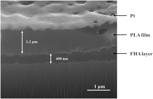
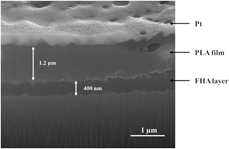
A typical cross section profile of FHA/PLA–coated sample is shown in Fig. 3. The micrograph shows the compact nature of the coating with a thickness of around 1.6 µm. The presence of two distinct layers of different colors can be seen. The inner layer comprises a thin nano-FHA layer with a thickness of 400 nm, whereas the outer layer is a thick PLA polymeric film with a thickness of 1.2 µm. Also, the polymeric film effectively sealed the pores present in the FHA layer. This feature potentially blocks the pathway for the infiltration of the attacking ions in a physiological medium and subsequently improves the corrosion resistance of Mg alloys. Previous studies have demonstrated the importance of coating thickness in influencing the anticorrosion behavior of Mg alloys, where a thicker coating can provide more effective and sustainable corrosion resistance [Reference Gu, Zheng, Cheng and Zheng48]. It should also be noted that the bioceramic FHA layer and the organic PLA film are bonded together. This result suggests the high interlocking strength of the bilayer structured coating on the AZ31 Mg substrates. More importantly, no clear gaps were seen between the FHA layer and the AZ31 Mg substrate, indicating a good adhesion strength between the coatings and the substrate. The adhesion strengths of the FHA coating were recorded to be in the range of 10–11 MPa. Comparatively, the bilayer FHA–PLA coating exhibited a higher adhesion strength of 13.5 MPa.
Cross-sectional SEM micrograph of as-deposited PLA/FHA coating on the Mg alloy AZ31.

Electrochemical behavior
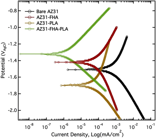
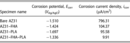
The electrochemical potentiodynamic polarization is an efficient tool to evaluate the corrosion resistance of materials. The process can enhance the corrosion reaction and accelerate the corrosion process, thus reducing the course of the experiment. The potentiodynamic polarization curves of the bare and coated AZ31 MG samples are shown in Fig. 4. The corresponding potentiodynamic parameters calculated based on these curves are tabulated in Table I. The polarization curves of FHA-, PLA-, and FHA/PLA–coated samples moved toward higher corrosion potentials and lowered corrosion current densities as compared with that of the uncoated AZ31 Mg sample. This result is an indication of favorable corrosion behavior. Particularly, the corrosion potentials (E corr) of FHA- and FHA/PLA–coated samples shifted to a more positive value with a slight increase of less than 90 mV and 180 mV, respectively [Reference Ren46]. The increasing positive corrosion potential indicates the approving thermodynamic stability state of the sample. The increase of thermodynamic stability in case of the FHA-coated sample is attributed to the ceramic nature of the deposited FHA layer and its high chemical stability in physiological conditions. On the contrary, the corrosion potential of the PLA-coated sample shifted to a lower value. However, potential does not necessarily represent the corrosion resistance of the coatings as corrosion potential primarily specifies the thermodynamic properties of materials, whereas the corrosion current density directly indicates the corrosion resistance properties of the materials. As seen in Table I, the corrosion current density (i corr) of PLA- and FHA-coated sample was reduced to about 95.58 and 104.37 µA/cm2, respectively, which are almost one order of magnitude lower than that of the bare alloy. These results confirmed that both PLA and FHA coatings possess the capability to prevent the ionic diffusion to the substrate, thus improving the corrosion resistance of the AZ31 Mg alloy. Moreover, a significant decrease in the corrosion current density was achieved by developing the PLA film and FHA layer on the AZ31 Mg surface. The corrosion current density (i corr) of FHA/PLA–coated specimen was less than bare AZ31 Mg by nearly two orders of magnitude, suggesting the outstanding corrosion resistance capabilities of FHA–PLA coating. This is because of the thick and compact structure of the deposited bilayer coating with effective sealing of FHA pores and defects by the PLA over-layer [Reference Li, Weng, Yuan, Luo, Wong, Liu, Wu, Yeung, Zheng and Chu49, Reference Bakhsheshi-Rad, Hamzah, Abdul-Kadir, Saud, Kasiri-Asgarani and Ebrahimi-Kahrizsangi50, Reference Zeng, Qi, Song, He, Cui and Han51].
Potentiodynamic polarization curves of uncoated, FHA-coated, PLA-coated, and PLA/FHA-coated AZ31 Mg alloy samples in SBF solution.

Electrochemical parameters of samples calculated from polarization curves.

In vitro degradation behavior
On immersion in the SBF solution, a set of reactions is believed to take place on the surface of Mg alloys. These chemical reactions define the corrosion of the Mg alloys as described in the following. First, the anodic dissolution reaction occurred on the Mg alloys surface according to the following reaction:
 $${\rm{Mg}} \to {\rm{M}}{{\rm{g}}^{2 + }} + 2{{\rm{e}}^ - }\quad .$$
Meanwhile, because of the occurrence of galvanic corrosion, the cathodic reaction took place simultaneously, which was also accompanied by the hydrogen evolution. Equation (3) represents the cathodic reaction which occurs in the electrolyte.
 $$2{{\rm{H}}_2}{\rm{O}} + 2{{\rm{e}}^ - } \to {{\rm{H}}_2} + 2{\left( {{\rm{OH}}} \right)^ - }\quad .$$
Later, the incorporation of Mg2+ and (OH)− induced the formation of insoluble precipitates of Mg(OH)2 which resulted in the formation of a passive layer Eq. (4) on the Mg surface. This passive layer could hinder the further anodic dissolution of Mg [Reference Ren, Zhou, Nabiyouni and Bhaduri39, Reference Yamamoto and Hiromoto52].
 $${\rm{M}}{{\rm{g}}^{2 + }} + 2{\left( {{\rm{OH}}} \right)^ - } \to {\rm{Mg}}{\left( {{\rm{OH}}} \right)_2}\quad .$$
However, with the presence of chloride ions (Cl−) in the electrolyte, insoluble Mg(OH)2 transformed into highly soluble MgCl2 according to the following reaction (5).
 $${\rm{M}}{{\rm{g}}^{2 + }} + 2{\rm{C}}{{\rm{l}}^ - } \to {\rm{MgC}}{{\rm{l}}_2}\quad .$$
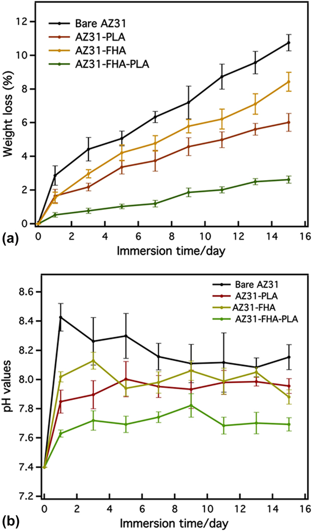
The aggressive attack by the corrosive ions easily dissolved the Mg(OH)2 passive layer which could be a protective layer. This removal is responsible for the exposure of the more reactive surface of the AZ31 Mg substrate, thus leading to severe pitting corrosion and rapid degradation [Reference Song, Shan, Chen, Zhang and Han53]. While analyzing the degradation properties of such material in vitro, it is important to consider two results: (i) the weight loss of the Mg alloy and (ii) the pH elevation of the SBF solution. In the present study, the mass loss and pH variations in SBF were continuously recorded to evaluate the in vitro degradation behavior of the coated AZ31 Mg alloy specimens. The immersion test results are presented in Fig. 5(a). The graph shows a rapid degradation for the bare AZ31 Mg samples during the first day, corresponding to the surface chemical reactions at the initial stage [Reference Meng, Guan, Wang, Wang, Zhu, Hu, Ren, Gao and Feng54]. Moreover, the PLA- and FHA-coated samples exhibited similar profiles of weight loss, but with less weight loss at each time point. By contrast, the FHA/PLA–coated samples presented the least weight loss, which is less than one-fifth of the weight of the bare AZ31 Mg, lost after 15 days of incubation in SBF [Reference Ren46]. These results confirmed that the FHA–PLA coating significantly improved the corrosion resistance and suppressed rapid degradation of the AZ31 Mg alloy in the physiological environment.
(a) Weight loss of surface-treated samples and the control sample and (b) variations of pH values of SBF solution at various immersion periods in SBF.

The surrounding pH value of the medium is an important factor for many cellular responses. Unsuitable pH conditions such as an rapid alkaline pH shift can cause several adverse effects on cell proliferation and adhesion [Reference Seuss, Seuss, Turhan, Fabry and Virtanen55]. Thus, the pH value change in the SBF solution was closely monitored during the immersion test and is presented in Fig. 5(b). It should be noted that the pH of the solution rose to 8.4 right on day 1. This is attributed to the severe corrosion reaction which took place at the early stage as described by Eqs. (2) and (3). However, later, the pH value steadily decreased because of the formation of the passive layer and also the precipitation of apatite on the material surface. On the contrary, the FHA-, PLA-, and FHA/PLA–coated specimens exhibited a small increment in the pH value at the beginning. Interestingly, the pH value of the solution incubating FHA/PLA–coated specimen was stabilized around 7.6, which is close to the value in blood plasma. This value favors the potential application of FHA/PLA–coated Mg alloys in the human body. Other than the excellent corrosion resistance properties of the deposited coatings, the presence of F− is also expected to decrease the pH value [Reference Bakhsheshi-Rad, Hamzah, Daroonparvar, Ebrahimi-Kahrizsangi and Medraj56]. Overall, the in vitro degradation behavior of the samples once again confirmed that the developed coatings are good candidates for protective corrosion-resistant coatings for AZ31 Mg alloys.
Corrosion & bioactivity assessment
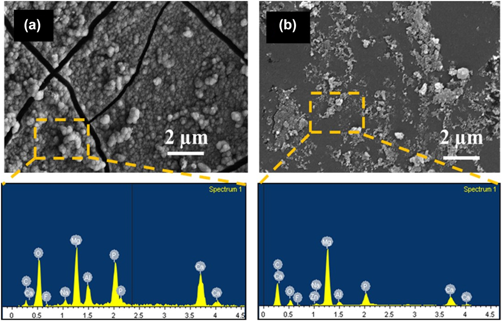
Figures 6(a) and 6(b) show the surface morphologies and elemental compositions of FHA- and FHA/PLA–coated samples after 15 days of immersion in t-SBF. Significantly big and deep cracks were formed on the surface of the FHA-coated sample [Fig. 6(a)] because of the severe corrosion reactions. The porous structure of the FHA coating allowed the percolation of the t-SBF ions through the coatings and corroded the substrate. Thus, such coatings do not exhibit promising anticorrosion characteristics. On the contrary, no significant changes in the morphology of FHA/PLA–coated specimens [Fig. 6(b)] were observed. Very few microcracks and corroded pits were seen on the FHA/PLA–coated specimens. It is evident that the PLA coating on top of the FHA deposition acted as an over-layer and resulted in significant reduction of galvanic corrosion.
Surface morphology and corresponding EDS spectra of (a) FHA and (b) FHA/PLA–coated AZ31 Mg alloy samples after 15 days of immersion in SBF.

The SEM micrographs also show the formation of numerous globules on the surface of the FHA-coated AZ31 Mg sample [Fig. 6(a)]. The corresponding EDS spectrum also revealed the high concentration of Ca and P from the globules. The globular structure and the presence of Ca and P indicate the formation of a bone-like apatite layer. Such apatite globules were also seen on HA whiskers [Reference Jalota, Bhaduri and Tas57] and newberyite platelets [Reference Sikder and Bhaduri5] in SBF immersion studies. The presence of such apatite globules indicates the high bioactivity of the material, in this case, FHA. The excellent bioactivity of FHA coating in vitro can be correlated to the promising bone-binding properties in vivo. The high bioactive nature can be due to two reasons (i) the porous structure of the as-deposited FHA coating significantly enlarged the surface area of the FHA layer and enhanced the release of OH− ions and ionic diffusion in t-SBF. This promoted the nucleation and crystal growth of apatite, and (ii) the smaller ionic radii and stronger electronegativity of the F− ions in the coating structure result in a more negatively charged surface, and thus induce an enhanced formation of Ca-rich amorphous CaP (ACP) precipitates. As the Ca-rich ACP precipitates are considered to be the nucleation site of bone-like apatite, FHA coating is anticipated to enhance the nucleation rate in SBF solution [Reference Ren46, Reference Fathi and Zahrani58]. By contrast, Fig. 6(b) shows the formation of sporadic apatite globules or precipitates [Fig. 6(b)] on the surface of FHA–PLA coating after t-SBF immersion.
Cytocompatibility analysis
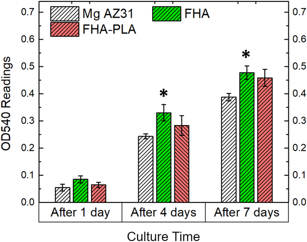
Preliminary cytocompatibility analysis is important to evaluate the biological responses of the biomaterials before in vivo assessment [Reference Ren, Sikder, Lin and Bhaduri8, Reference Sikder, Koju, Lin and Bhaduri15]. Figure 7 shows the MTT assay results of the various specimens cultured with MC3T3 pre-osteoblasts. The cell viability measured by MTT assay presents a significant increase (P < 0.05) in case of AZ31-FHA samples with respect to the bare AZ31 control. This could be due to three reasons—(i) the favorable biocompatibility nature of fluorapatite due to the presence of Ca2+ and F− ions, (ii) the flake-like FHA coatings provide an approving surface texture for the pre-osteoblasts to adhere, (iii) the FHA coatings does not allow the formation of H2 bubbles because of the lack of corrosion, hence allowing the cells to attach. The FHA–PLA bilayer coatings also exhibited comparable cytocompatibility results with respect to only FHA coatings. Thus, the developed coatings were biocompatible with mammalian cells in addition to their corrosion resistance nature.
Cytocompatibility assays results of different specimens as cultured with MC3T3 pre-osteoblasts.

Conclusion
In this work, two kinds of coatings were produced on the AZ31 Mg alloy: (i) FHA monolayer coating and (ii) FHA–PLA bilayer coating. These were synthesized using a combined technique involving a facile microwave-assisted coating process and spin coating. The FHA–PLA hybrid coating consisted of a thin FHA ceramic layer with a thick PLA polymeric layer developed on top of it. Even though the FHA layer had a thickness of 400 nm and covered the substrate uniformly, the coatings were porous, whereas the outer PLA layer had a thickness of 1.2 µm with a compact structure and effectively covered the defects and pores of the FHA layer. Electrochemical tests and the in vitro degradation test were used to investigate the corrosion resistance and degradation behavior of the AZ31–FHA and AZ31–FHA–PLA samples in the physiological environment. As expected, the FHA–PLA coating suppressed the corrosion current density and degradation rate of AZ31 Mg alloys significantly. Moreover, the FHA coating was highly bioactive and induced the copious amount of bone-like apatite globules on the coating surface, thus signifying its great potential in bone regeneration applications.
Experimental
Material preparation
AZ31 Mg alloy (3% Al, 1% Zn) sheets were cut into 1 cm × 1 cm × 2 mm dimension blocks. They were grinded with silicon carbide (SiC) abrasive paper up to #1200 grit to ensure a homogeneous surface roughness. After grinding, the blocks were ultrasonically cleaned in 70% ethanol three times followed by rinsing in deionized (DI) water. Finally, they were dried at 60 °C for 30 min and air cooled.
FHA deposition
The coating solution for FHA deposition is described as follows. 1.9836 g of magnesium nitrate hexahydrate [Mg(NO3)2·6H2O > 99% purity], 0.6048 g of sodium dihydrogen phosphate (NaH2PO4, >99% purity), and 0.0705 g of sodium fluoride (NaF, >99% purity) were added to 200 mL DI water on constant stirring at 260 rpm until they were dissolved. All the chemicals were procured from Fisher Scientific and used without further purification. In another 200 mL beaker, two grinded AZ31 Mg substrates were placed and filled with 100 mL of the prepared coating solution. The top of the beaker was covered by an alumina fiberboard (Zircar Ceramic, Florida, New York), and the entire setup was placed in a 1200 W microwave oven (Panasonic, Japan). The setup was then heated at maximum power for 5 min. The uniformity of the coatings is ensured by pouring 100 mL of the coating solution in the same beaker containing the specimens and irradiated for another 5 min. Finally, the coated samples were retrieved, rinsed in DI water, and dried in an oven at 60 °C. These coated specimens are designated as AZ31–FHA.
Spin coating
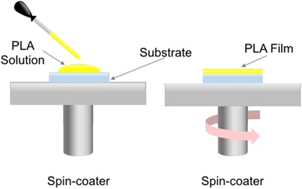
To develop the PLA film, we chose to use a one-step spin coating technique. First, PLA powders were weighed and dissolved in chloroform following 4% (w/v) ratio. After a homogeneous mixing of the PLA solution, they were uniformly spread on bare AZ31 Mg substrates and FHA-coated AZ31 Mg blocks with the help of a micropipette. The spin-coating technique was set for 30 s at a rotating speed of 3000 rpm. After the PLA films were developed, they were immediately dried in a dehumidified environment at room temperature. To ensure a uniform and thick PLA film, the spin-coating process was repeated for three times. Figure 8 represents the schematic diagram of the spin-coating process. After coating, the specimens were stored at room temperature for further characterization. Either only PLA coatings on bare substrates (AZ31–PLA) or PLA on already FHA-coated specimens (AZ31–FHA–PLA) were developed.
Schematic diagram of the setup of spin-coated and the PLA film deposition of spin coating.

Coating characterization
Analyses of phases present in the as-coated samples and bare AZ31 Mg were conducted by X-ray diffraction (XRD; Ultima III, Rigaku, Woodlands, Texas) with Cu Kα radiation over a 2θ range of 10–60° generated at 44 kV and 40 mA. The functional groups present were detected by Fourier transform infrared spectroscopy (FTIR; UMA-600 Microscope, Varian Excalibur Series) using an ATR diamond crystal for 256 scans in the range between 4000 and 700 cm−1 with a resolution of 1 cm−1. Surface morphology and elemental composition were examined using scanning electron microscopy (SEM; S4800, Hitachi) equipped with an energy dispersive X-ray spectroscopy (EDS; Oxford INCA). An accelerated voltage of 20 kV with a working distance of 15 mm was used for the EDS analysis. Cross section specimens to study the coating thickness were prepared using focused ion beam (FIB). A mechanical testing machine (858 Bionix, MTS) was used to measure the adhesion bond strengths of the coatings to the substrate. Aluminum studs were mounted and aligned carefully onto the specimens using epoxy glue and cured at 100 °C for 1 h. After the setup cooled down to room temperature, they were placed in specially designed fixtures in the mechanical testing machine and pulled with a speed of 0.5 mm/min until failure. The recorded load at failure was used to calculate the adhesion strength [Reference Sikder, Grice, Lin, Goel and Bhaduri42].
Electrochemical test
Potentiodynamic polarization tests were conducted using Gamry Reference 600 potentiostat to evaluate the corrosion behavior of coated and uncoated samples. The test was conducted in simulated body fluid (t-SBF). In our studies related to SBF immersion, we have been using t-SBF, a modified version of SBF. It was prepared by dissolving 6.547 g NaCl, 2.268 g NaHCO3, 0.373 g KCl, 0.178 g Na2HPO4⋯2H2O, 0.305 g MgCl2⋯6H2O, 0.368 g CaCl⋯2H2O, 0.071 g Na2SO4, and 6.057 g tris-buffer, and 40 mL of 1 M HCl, respectively, in 1 L DI water [Reference Jalota, Bhaduri and Tas59]. All reagents were procured from Fisher Scientific and used without further purification. The reagents were added one by one, and finally, a clear solution was obtained. For the potentiodynamic test, a conventional three-electrode arrangement was used. The setup comprised the sample as the working electrode, the Ag/AgCl electrode as the reference electrode, and the graphite rod as the counter electrode. The potentiodynamic polarization curves were measured at a scan rate of 1 mV/s after a steady open circuit potential (OCP) was achieved.
In vitro degradation
The test for degradation behavior of uncoated and coated samples were evaluated following the ASTM-G31-72 standardization. The samples were tested using an immersion test in t-SBF. Each sample was kept in 60 mL t-SBF for 15 days in a thermostatic water bath which maintained 37 ± 0.5 °C. The t-SBF solution was also replenished every other day. During the course of the test, the pH value of t-SBF solution was monitored using a pH meter (Mettler Toledo). At certain time frames, the samples were retrieved, rinsed with DI water, and air-dried. Subsequently, the weight losses of the specimens were recorded to determine the degradation rate. The degradation rate, in terms of the relative percentage of mass loss, was derived from following equation:
 $${W_{_{\rm{L}}}} = \left( {{{{W_1} - {W_0}} \over {{W_0}}}} \right) \times 100,$$
where W L, W 0, and W 1 are the percentage of weight loss, and the weights before and after immersion for different time intervals, respectively.
Bioactivity assessment
To study the bioactive nature of the coatings, specimens were immersed in 60 mL of t-SBF for 15 days. The temperature for incubation was maintained at 37 ± 0.5 °C. To maintain the ionic compositions constant, t-SBF was replenished after every 2 days. After two weeks of immersion, bare and coated samples were retrieved and washed in flowing DI water to remove any loose particles from the surfaces. Then, the samples were completely dried at 60 °C. Finally, they were sputter-coated and analyzed under the SEM to evaluate the extent of bioactivity properties.
Cytocompatibility assay
Model osteoblastic cell line–mouse calvarial pre-osteoblasts designated as MC3T3-E1 (ATCC CRL-2593) were used to check the cytocompatibility of the coated specimens. Cells were cultured in minimum essential medium alpha (MEM-α; Thermo Scientific, Logan, Utah), supplemented with 10% fetal bovine serum (FBS; Thermo Scientific HyClone) and 1% penicillin/streptomycin (0.2 g/mL), known as complete MEM-α, at 5% CO2 and 37 °C.
Specimens were placed in 24-well plates and seeded with approximately 4 × 10⁴ cells and incubated at 37 °C with 5% CO2 flow for 1, 4, or 7 days. The complete medium was replenished every third day. At specific time points, well plates were retrieved from the incubator and the specimens were treated with thiazolyl blue tetrazolium bromide (MTT, Sigma-Aldrich, St. Louis, Missouri) and incubated for 4 h. Subsequently, dimethyl sulfoxide (DMSO) was used to dissolve the formazan followed by a short incubation for 10 min. Eventually, OD540 readings were recorded by a spectrophotometer and compared.
Acknowledgment
This work is funded by NSF Grant No. 1706513.