Introduction
The most commonly employed test for the determination of the static Young's modulus of a material is probably the uniaxial compression test for solid circular cylinders.[ Reference Chau 1 ] It has advantages in specimen preparation and experiment operation, with a simple mechanical model. Studies have shown that some materials, such as ceramics, concrete, graphite, and some composites, exhibit different elastic moduli in tension and compression, which is known as bimodular materials.[ Reference Jones 2 – Reference Medri 4 ] Compression tests are irreplaceable for these bimodular materials and other anisotropic materials, such as unidirectionally reinforced composite materials and highly textured materials deformed by twinning.[ Reference Backofen 5 ] Furthermore, to understand the behavior of materials under large plastic strains, compression test is more appropriate than the tensile test because the latter is limited by necking.[ Reference Kuhn, Kuhn and Medlin 6 ] Especially, the compression test is easier for metallic glass to produce plasticity than the tensile test.[ Reference Schroers and Johnson 7 – Reference Song, Beib, Wadsworthc and Nieha 9 ]
However, the drawback of compression tests is that the tested modulus is usually different from the intrinsic value. It has long been recognized that friction inevitably exists between the loading platens and the upper and lower end surfaces of the cylindrical specimen, which will influence the test results.[ Reference Chau 1 , Reference Williams and Gamonpilas 10 ] To acquire the compression modulus as reliable as possible, a high aspect ratio (≥8) is recommended by ASTM E9-09.[ 11 ] However, specimens of high aspect ratio (>5) can only be used in small deformation tests because they are susceptible to buckling. To inspect the material response under big strain in compression tests, specimens with middle aspect ratio (2.5–3.5) are recommended and also widely used actually. Now a problem is brought forward, that is, whether it is possible to get the true (or nearly true) compression modulus from a middle aspect ratio specimen.
In this paper, a “sandwich” model is developed considering the stress concentration near the interface between the specimen and the compression platen. Then, a correction method is brought forward for linear hardening materials. Experiments are performed to verify the effectiveness of the correction method.
Experiment
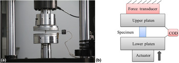
Compression experiments were performed on aluminum alloy (Al 2024) cylindrical specimens with diameters of 10 mm and aspect ratios of 2.0, 2.5, 3.0, and 3.5, respectively. MTS 810 testing machine was used and the strain rate was controlled at 10−3/s. The schematic diagram of the test setup is demonstrated in Fig. 1. A crack opening displacement (COD) transducer was applied to measure the displacement between two platens for strain calculation.
Compression testing machine: (a) photograph and (b) schematic diagram.

To obtain the intrinsic modulus of Al 2024, another compression experiments were conducted on bone-like slim specimens with 28 mm gauge length and 4 mm diameter using INSTRON ElectroPuls E1000 test instrument. A video extensometer was adopted to measure the strain of the gauge section, where the precondition of one-dimensional stress model could be well satisfied. Three specimens were separately tested in order to ensure the repeatability.
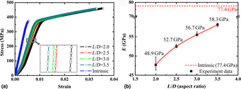
At least three specimens were separately tested for each kind of cylindrical specimens with aspect ratios from 2 to 3.5. Each stress–strain curve was obtained by averaging the experimental data of three specimens, shown in Fig. 2(a). Similarly, the test result of intrinsic compression modulus, given to be 77.4 GPa, is also illustrated by circle points in Fig. 2(a). All the tested results of the compression modulus are much less than the intrinsic value. It can be easily concluded that the tested values have a positive correlation with the aspect ratio, shown in Fig. 2(b). This phenomenon clearly illustrates the relevant regulations in ASTM E9-09 that only slim specimens (with aspect ratio equal to or greater than 8) are suitable for the compression modulus tests.[ 11 ]
Compression test results of Al 2024 cylindrical specimens with various aspect ratios. (a) The tested true stress–strain curve, where aspect ratios from the left to the right are 2.0, 2.5, 3.0, and 3.5; (b) relationship between the tested modulus and the specimens’ aspect ratio.

Theoretical analysis
Slanted contact
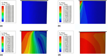
An arc is shown at the beginning of the stress–strain curve, which indicates the slanted contact between compression platen and specimen surface. Of course, the contact of two plates must undergo the changes from point-contact to plane-contact because absolute parallel planes do not exist in practice. The whole process of contact between platen and specimen is illustrated by finite-element simulation in Fig. 3 from (a) to (d). Just due to the slanted contact, the stress near the contact interface is greater than that in the middle segment of specimen along with loading, as shown in Fig. 3(b). Gradually, the materials near the contact interface become plastic just one step ahead of the middle segment of the specimen, shown in Fig. 3(c). Along with the load increasing, the whole specimen becomes plastic finally, shown in Fig. 3(d).
Finite-element simulation of slanted contact between compression platen and specimen surface. (a) Before contact; (b, c) incomplete contact; and (d) complete contact.

Correction method
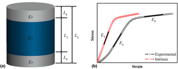
Based on the discussion above, a “sandwich” model composed of a hard segment and two soft segments is put forward to simplify the compression process, shown in Fig. 4(a). Suppose that the modulus of the material in the hard segment is E T (the intrinsic compressive elastic modulus), and the one in the soft segments is E P (the slope of the hardening segment of the stress–strain curve), shown in Fig. 4(b). Additionally, it is ideally assumed that both hard and soft segments will undergo purely elastic and homogeneous deformation during compression. Consequently, the total axial deformation of the whole model ΔL S can be calculated as,
 $${\rm \Delta} {L_{\rm S}} = {\rm \Delta} {L_{\rm T}} + 2{\rm \Delta} {L_{\rm P}},$$
where ΔL T and ΔL P are the axial deformation of the hard segment and the soft segment, respectively. According to Hooke's law, the elastic modulus of the whole model and each part are defined as
 $$\left\{ {\matrix{ {{E_{\rm S}} = \displaystyle{F \over A}/\displaystyle{{\Delta {L_{\rm S}}} \over {{L_{\rm S}}}},} \cr {{E_{\rm T}} = \displaystyle{F \over A}/\displaystyle{{\Delta {L_{\rm T}}} \over {{L_{\rm T}}}},} \cr {{E_{\rm P}} = \displaystyle{F \over A}/\displaystyle{{\Delta {L_{\rm P}}} \over {{L_{\rm P}}}},} \cr}} \right.$$
where F is the compressive force; A is the area of the cross-section; L S is the total length of the specimen; L T and L P are the length of the hard segment and the soft segment, respectively. By substituting Eqs. (2) into (1), the following relation is derived as:
 $$\displaystyle{{{\rm \Delta} {L_{\rm S}}} \over {{E_{\rm S}}}} = \displaystyle{{{\rm \Delta} {L_{\rm T}}} \over {{E_{\rm T}}}} + \displaystyle{{2{\rm \Delta} {L_{\rm P}}} \over {{E_{\rm P}}}}.$$
The “sandwich” model with its parameters. (a) The schematic diagram of the “sandwich” model, the gray part is the soft segment with elastic modulus E P and length L P , the blue part is the hard segment with elastic modulus E T and length L T . (b) Schematic diagram of the tested (square points) and intrinsic (circle points) stress–strain curve, the black straight lines in the curves are linear fitted lines of elastic and hardening sections with slope values of E T , E S, and E P , respectively.

If β is defined as the volume fraction of the soft segment,
 $$\beta = \displaystyle{{{V_{\rm P}}} \over {{V_{\rm S}}}} = \displaystyle{{{L_{\rm P}}} \over {{L_{\rm S}}}}.$$
By substituting Eqs. (4) into (3), the corrected modulus E C is obtained,
 $${E_{\rm C}} = {E_{\rm T}} = \displaystyle{{(1 - 2\beta ){E_{\rm S}}{E_{\rm P}}} \over {{E_{\rm P}} - 2\beta {E_{\rm S}}}}.$$
It should be noted that Eq. (5) is only adapted to linear hardening materials.
Determination of β
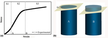
As the soft segments are derived from slanted contact, the volume fraction β can be evaluated according to the volume compressed by the compression platen. With the platen moving down along the axis, the compression process would undergo from incomplete contact to complete contact then to plastic compression, corresponding to three stages of the tested stress–strain curve, respectively, shown in Fig. 5(a).
Illustration of the compression process. (a) Three stages of tested stress–strain curve—incomplete contact (S1), complete contact (S2), and plastic compression (S3). (b) The bright sideling plane, standing for upper platen surface, moves down along the axial of the specimen. Two critical states during compression—two planes just contact completely (A) and the whole specimen just yields (B).

The volume of compressed region is calculated as following:
 $${\rm \Delta} V = \left\{ \matrix{\int {y \cdot z \cdot dx} = \int_0^{{\rm \Delta} L/\tan \theta} \sqrt {Dx - {x^2}} \cr \quad\quad\quad\quad\quad\cdot \left( {{\rm \Delta} L - x\tan \theta} \right) \cdot dx{\rm} & \left( {0 \le {\rm \Delta} L \le D\tan \theta} \right) \hfill \cr \displaystyle{1 \over 2}\left( {{\rm \Delta} L + {\rm \Delta} L - D\tan \theta} \right) \cdot \displaystyle{{\pi {D^2}} \over 4}{\rm} & \left( {D\tan \theta \le {\rm \Delta} L \le L} \right), \hfill} \right.$$
where D and L are the diameter and length of the specimen, respectively; ΔL is the axial deformed length of the specimen; θ is the angle between the two contacted surfaces. β is derived as
 $$\beta = \displaystyle{{{\rm \Delta} V} \over V} = \left\{\matrix{\int_0^{{\rm \Delta} L/\tan \theta} \sqrt {Dx - {x^2}} \cr \cdot \left( {{\rm \Delta} L - x\tan \theta} \right) \cdot dx / {\displaystyle{{\pi {D^2}L} \over 4}} & \left( {0 \le \varepsilon \le \displaystyle{D \over L}\tan \theta} \right) \cr \varepsilon - \displaystyle{{\tan \theta} \over 2} \cdot \displaystyle{D \over L}{\rm} & \left( {\displaystyle{D \over L}\tan \theta \le \varepsilon \le 1} \right).} \right.$$
There exit two critical states during compression. In critical state A, showed left in Fig. 5(b), the upper platen and the upper surface of specimen just contact completely, and the axial deformed length of the specimen (ΔL) at this moment is calculated as,
 $$\Delta L = D\tan \theta = {\varepsilon _{\rm A}}L,$$
where ε A is the strain value at the beginning of the elastic segment.
In critical state B, as shown right in Fig. 5(b), all materials of the three segments become yielded, corresponding to the yield point (defined as σ 0.2) in stress–strain curve. At this moment, the volume fraction of the plastic region β is calculated as
 $$\beta = {\varepsilon _{\rm B}} - \displaystyle{{{\varepsilon _{\rm A}}} \over 2},$$
where ε B is the strain value of the yield point.
It is noted that the correction method is also applicable to other incomplete contact compression tests, such as rough surface contact scenario, because the parameters in Eqs. (5) and (9) just depend on the stress–strain curve.
Experimental verification
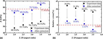
To verify the correction method, the compression modulus of the Al 2024 specimens with aspect ratios of 2.0, 2.5, 3.0, and 3.5 were calculated using Eq. (5). The values of E S, E P , ε A, and ε B could be obtained from the compression stress–strain curve into Eqs. (5) and (9), shown in Table I. The results before and after correction are shown in Fig. 6. For specimens with different aspect ratios, the tested moduli range from 48.9 to 58.3 GPa. Compared with the intrinsic modulus of 77.4 GPa, the relative deviations are from 24.7% to 36.8%. The corrected values are from 69.2 to 84.1 GPa, corresponding to the relative deviations from 8.6% to 10.6%. It could be seen that corrected results are closer to the intrinsic compressive elastic modulus than the tested values.
(a) Modulus and (b) the relevant relative deviations of Al 2024 specimens before (solid square points) and after (solid dots) corrections.

Parameters obtained from stress–strain curves of Al 2024 in Fig. 2.

Conclusion
In this paper, the cause of the deviation between the tested compression modulus and the intrinsic value is analyzed and a correction method is brought forward. The slanted contact between the specimen and the compression platen leads to an inhomogeneous stress field, which destroys the assumption of one-dimensional stress. For linear hardening material, a “sandwich” model is developed to simplify the compression process and a correction method is brought forward. Compression experimental results of Al 2024 specimens, with aspect ratio from 2 to 3.5, show that the maximum deviation of the tested modulus can be corrected from 36.8% to 10.6%, which demonstrates the effectiveness of the correction method.
Acknowledgments
This work is supported by the National Natural Science Foundation of China (Grant numbers 11372323, 11202209, and 11472275) and Opening fund of State Key Laboratory of Nonlinear Mechanics.