





1. Introduction
Repetitive and heavy lifting is one of the leading causes of injury in the workplace, with over 100,000 injuries each year related to overexertion in lifting, lowering, holding, or carrying objects in the United States (Bureau of Labor Statistics, U.S. Department of Labor, 2018). Additionally, work-related musculoskeletal disorders (MSDs) continue to be nationally recognized as significant work-related health problems impacting productivity of industrial nations (Waters, Reference Waters2004; Bevan, Reference Bevan2015). Even with proper lifting form, there are limits to the maximum loads that a single person can lift and carry. Traditionally, multiple people are used to lift heavy objects with “team lifts.” The greatest challenges for lifting are when loads surpass 20 kg (44 lbs) (Park et al., Reference Park, Kim, Nussbaum and Srinivasan2022).
Exoskeletons are one solution to the problem of heavy lifting. Some powered exoskeletons have been designed to be used by able-bodied individuals to lift heavy objects, minimizing injuries resulting from lifting, or reducing the number of people needed to perform a heavy lift. These exoskeletons typically power both their legs and arms, transferring the forces from a carried object down to the floor. This bypasses the wearer’s musculoskeletal system, reducing the strain on their body. We refer to these exoskeletons as full body “heavy lift and carry” exoskeletons. These systems often prioritize complete joint-level actuation to replicate human biomechanics, but this comes at the cost of additional actuators that increase weight and complexity.
A summary of existing heavy lift and carry exoskeletons is presented in Table 1. These have been powered with electric motors, pneumatically, and hydraulically. They have as many as 30 controlled Degrees of Freedom (DOF), or as few as 5, and have masses between 23 and 100 kg.
Summary of the prior work in Heavy Lift and Carry exoskeletons

Table 1. Long description
Table comparing prior work in Heavy Lift and Carry Exoskeletons. This includes the exoskeleton mass, lifting capacity, ratio of lifting capacity to mass, degrees of freedom, and actuation method.
Note: The “LC/Mass” column is the Lifting Capacity per exoskeleton mass, and the table is sorted by this column. The table is divided into three sections: the top section includes untethered exoskeletons where the Lifting Capacity is for the arms-outstretched configuration. The middle section includes tethered exoskeletons again with the arms-outstretched Lifting Capacity. The bottom section includes untethered exoskeletons, but where the Lifting Capacity is for loads close to the body because they do not support the arms-outstretched posture
References: FB-AXO: (Christensen et al., Reference Christensen, Rafique and Bai2021; Bai et al., Reference Bai, Islam, Power and OŚullivan2022 ); Power Loader: (Ishida et al., Reference Ishida, Kiyama, Osuka, Shirogauchi, Oya and Fujimoto2010 ); Sarcos Guardian XO: (Sarcos Research Corporation, 2022; Park et al., Reference Park, Kim, Nussbaum and Srinivasan2022 ); Sarcos XOS-2: (Karlin, Reference Karlin2011; Jacobsen et al., Reference Jacobsen, Olivier and Maclean2014 ); Body Extender: (Marcheschi et al., Reference Marcheschi, Salsedo, Fontana and Bergamasco2011; Fontana et al., Reference Fontana, Vertechy, Marcheschi, Salsedo and Bergamasco2014 ); Daewoo Electro-Hydraulic Exo and Electric Exo: (Chu et al., Reference Chu, Hong, Jeong, Kim, Kim, Jeong and Choo2014 ); Power Assist Suit: (Ishii et al., Reference Ishii, Yamamoto and Hyodo2005 ); Hybrid Assistive Limb (HAL 5): (Guizzo and Goldstein, Reference Guizzo and Goldstein2005 ; Sankai, Reference Sankai2010 ).
a The Daewoo Electric Exo and Electro-Hydraulic Exo do not support the arms-outstretched posture because the Electric version has a fixed hook on the front and the Electro-Hydraulic version uses an overhead crane that supports the load close to the wearer’s chest.
b Note that the Power Assist Suit does not provide power to the shoulders, so does not support the arms-outstretched posture; the Lifting Capacity is solely with the elbow.
c While not specified in the publications, the Hybrid Assistive Limb (HAL 5) exoskeleton appears to have its lifting capacity close to the body.
In general, some designs have attempted to minimize the number of actuators to minimize exoskeleton mass and complexity, while others power nearly all of the DOF. For the upper body, several designs just power the elbow and do not power the shoulders, minimizing the number of actuators but preventing the exoskeleton from helping if the load is held away from the body (Ishii et al., Reference Ishii, Yamamoto and Hyodo2005; Sankai, Reference Sankai2010). Two designs do not have arms at all, instead holding the load with a crane that extends from the back to the front of the body (Chu et al., Reference Chu, Hong, Jeong, Kim, Kim, Jeong and Choo2014). For the lower body, several of the designs only use actuators in the sagittal plane for the hip and knee to support walking, leaving the other DOF unpowered (Ishii et al., Reference Ishii, Yamamoto and Hyodo2005; Chu et al., Reference Chu, Hong, Jeong, Kim, Kim, Jeong and Choo2014; Christensen et al., Reference Christensen, Rafique and Bai2021; Bai et al., Reference Bai, Islam, Power and OŚullivan2022). Thus, there are four actuators required for the two legs in these designs. Still other designs power additional joints in the legs (Ishida et al., Reference Ishida, Kiyama, Osuka, Shirogauchi, Oya and Fujimoto2010; Marcheschi et al., Reference Marcheschi, Salsedo, Fontana and Bergamasco2011). In contrast, in this work we explore using only a single actuator for each leg of the exoskeleton, as a means of simplifying the design.
Although no current heavy lift and carry exoskeleton uses only a single actuator in each leg, several walking-assistance exoskeletons have adopted this simplified architecture. Some exoskeletons use just a single actuator at or near the knee to provide support forces between a loaded backpack and the ground. These include OLAD (Hollander et al., Reference Hollander, Clouse, Cahill, Boehler, Sugar and Ayyar2012), Exobuddy (Van Dijk et al., Reference Van Dijk, Van de Wijdeven, Holscher, Barents, Könemann, Krause and Koerhuis2018), a design by Yu et al. (Reference Yu, Han and Cho2014, Reference Yu, Lee, Kim and Han2016), a design by Long et al. (Reference Long, Du, Chen, Wang, He, Mao, Xu, Zhao, Li and Dong2017), and designs by Kim et al. (Reference Kim, Lee, Lim, Han and Han2013) and HD Lee et al. (Reference Lee, Kim, Lim and Han2017). Finally, Parallel Actuated Lower Limb Exoskeleton (PALExo) uses two linear actuators per leg but they are arranged in an unusual fashion, with both extending from the waist to the foot (Wang et al., Reference Wang, Zhu, Zheng, Sui, Zhao and Zhao2020). While these studies show progress toward simplified systems, none demonstrate a full-body heavy-lift exoskeleton capable of supporting large external loads during both lifting and walking with only a few actuators. This gap motivates the design presented here.
In this work, we present a novel design for an underactuated Heavy Lift and Carry Exoskeleton (the HeavyLC Exo) capable of enabling a single person to lift 36 kg (80 lbs) using both arms (or 18 kg with one arm) from the ground to above their head and walk while holding the load (Figure 1). These performance objectives were selected to represent demanding heavy material-handling tasks encountered in applications such as manufacturing, construction, warehousing, and military logistics, where workers may be required to lift and place heavy loads onto elevated surfaces. Our work includes several novel contributions: (1) The legs are powered by only a single actuator on each side, connecting the torso of the exoskeleton with the wearer’s foot. This design differs from existing heavy lift and carry exoskeletons that primarily provide joint-based assistance; instead, it delivers direct support to the ground through a single actuator, simplifying the structure while still allowing its wearer to walk. (2) The combined center of mass (COM) of the user, Exo, and load is analyzed to optimize the position of the top of the actuators, minimizing the torques the user must supply to aid in lifting and carrying. (3) The hip joint features a novel unidirectional leaf spring that supports hip adduction during loaded walking, creating a torque during the stance phase to support the load in the frontal plane. The appropriate spring stiffness is determined through analysis, and the exoskeleton’s stiffness is characterized. Together, these design choices represent a unified approach to achieving functional heavy-lift assistance with the fewest possible actuators by combining active and passive elements to simplify hardware and control.
Overview of the HeavyLC Exo, showing several views of an individual performing various lifting and walking sequences while wearing the exoskeleton. (a) Front view. (b) Side view. (c) Lifting 80 pounds with just a few fingers on each hand. (d) Top view. (e) Close-up of the legs showing the ability to walk and the ability of the legs to move in all directions.

In this article, we first provide the detailed development of the exoskeleton’s mechanical structure, including the minimal-actuation framework that combines powered and passive elements to support both lifting and walking. We then describe the implementation of the pneumatic control system and state machine architecture for coordinating upper and lower body actuation. Finally, we characterize actuator behavior and report actuator responses, demonstrating the exoskeleton’s capability to lift loads up to 36 kg and support loaded walking.
2. Exoskeleton overview
An overview of the HeavyLC Exo’s functionality, actuation, features, and sensors is provided in Figure 2 while its key specifications and range of motions are summarized in Table 2.
Overview of the HeavyLC Exo depicting various features, sensors, and actuated and unactuated degrees of freedom.

Key specifications of the HeavyLC Exo. Approximate active joint ranges of motion for healthy adult male subjects are included for comparison

Table 2. Long description
Full table of specifications including the mass, payload, DOF, and Range of Motion.
a Leg adduction includes a leaf spring. Adult male ROM values are approximate and adapted from Boone and Azen (Reference Boone and Azen1979).
The HeavyLC Exo is secured to the user with shoulder, chest, and thigh straps, a waist belt, and an “overshoe” that surrounds the wearer’s footwear.
The arms use only two actuators each, to provide powered lifting (elevation) and arm extension. The third DOF (motion in the horizontal plane) is not powered since the forces are usually perpendicular to gravity and thus relatively low. The arm’s mechanical design supports high forces yet minimizes interference with the user, allowing for a wide range of body postures. At the end of each arm, there is a handle equipped with a safety switch for the user to hold and a tool hook to pick up and carry objects. The handles also direct the HeavyLC Exo’s control system, which responds with a minimal amount of resistance (See Table 2). Each arm operates independently.
The lower body is even more simplified, with one actuator for each leg, a free ball joint at the ankle, and a free universal joint at the hip. Thus, the HeavyLC Exo requires the user to rely on their own balance to remain upright in the sagittal plane to keep the COM of the combined system (user, Exo, and held load) over their feet.
The HeavyLC Exo has a total of 20 DOF (10 DOF per side), with 6 actuated DOF and 14 unactuated DOF (see Table 2). Once powered, the suit supports its own 67.4 kg (148.5 lbs) mass plus a payload. Six pneumatic actuators – two for each arm and one per leg – power the suit, supplied by an off-board air compressor providing 482.63 kPa (70 psi) of air pressure. Two of the passive DOF in the hip include leaf springs to support adduction of the leg during single-leg support. The remaining DOF are intentionally designed to be free to allow for less hindered walking and unrestricted horizontal arm abduction motions, but this behavior requires the user to maintain active balance. With each arm operating independently, the suit can compensate lifting and carrying of objects up to 18 kg (40 lbs) per arm and 36.2 kg (80 lbs) in total, leaving a small percentage (3–11%) of weight for user feedback so the load feels natural to the user without complete weightlessness. The HeavyLC Exo structure was designed with a factor of safety of 3–5 for safety.
3. Exoskeleton mechanical design
3.1. Upper body design
The HeavyLC Exo upper body can be divided into the following assemblies: the shoulder assembly housing the two actuators and supporting structure (Figure 3(a, c)), the tool attachment assembly containing the user object control tool and force feedback systems (Figure 3(b)), and finally the arm support assembly redirecting the forces external to the body (Figure 4). The exoskeleton arms are designed to go on the outside of the user’s arms, so they can accommodate a wide range of user hand positions. Only two DOF are powered, allowing for the arm to horizontally abduct and adduct freely. The range of motion of the exoskeleton joints is shown in Table 2.
CAD model of the HeavyLC Exo upper body design with key components labeled. (a) Upper arm side view, (b) tool attachment isometric view, and (c) upper arm back-isometric view. The seesaw is a hinged force–transmission linkage that provides a 5:1 mechanical ratio between the hook load and the force measured by the sensor.

CAD model of the HeavyLC Exo back-plate body design depicting joints for upper and lower limbs with key components labeled. The U-joints permit free hip motion, while the hip leaf springs provide passive frontal-plane support; these lower body components are described further in Section 3.2.

The shoulder sub-assembly, shown in Figure 3(a, c), uses two actuators to control the arm: one controls the elevation (inclination) of the arm, while the other controls the arm extension (in-out). The elevation sub-assembly (Figure 3(a)) is made up of a 7.32 cm (3″) diameter bore pneumatic actuator (McMaster 6498 K698) connected to a Technora 0.95 cm (3/8″) diameter rope (McMaster 3790 T34). This rope passes around two small pulleys and then is wrapped around a large 13.2 cm (5–3/16″) inner diameter fixed pulley (McMaster 3164 T82). As the actuator retracts, the rope converts the linear motion into rotary motion via the fixed pulley. This creates a moment about the shoulder that elevates the arm. Because the actuator is single-acting, the arm is lowered by gravity while air is released slowly from the pneumatic actuator, preventing the exoskeleton arm from dropping abruptly. The large pulley is fixed to the shoulder structural framing secured to the backplate.
The extension/retraction sub-assembly consists of a triangular profile array of an actuator and supporting tubing. The actuator is a 3.18 cm (1.25″) diameter bore pneumatic actuator (McMaster 6498 K464), affixed in parallel to two supporting telescoping tubes. The actuator can both extend and retract, assisting the extension and retraction of the arm.
The tool attachment assembly, shown in Figure 3(b), is made up of an aluminum frame with a protruding handle for user control and a hook tool to hold a load. The hook tool is pinned and able to rotate freely about the wrist to orient in position for an object, while pressing against a force sensor via a hinged bar providing a 5:1 ratio of the object weight to sensed weight. The 5:1 ratio is determined by the geometry of the seesaw linkage, which mechanically scales the hook force before it is measured by the load cell.
The arm support assembly, shown in Figure 4, consists of hinged square tubing affixed to the backplate to transfer the weight of the load on the arm to the HeavyLC Exo frame. The hinged revolute joint allows for a free degree of rotation for horizontal abduction of the user’s arm. It is located posterior to the shoulder to keep the HeavyLC Exo arm external to the user’s body and out of the arm’s range of motion. The support assembly arm is adjustable to the user’s shoulder width using bolts that attach the square tubing to the backplate.
3.1.1. Actuator sizing
With the design criteria of the HeavyLC Exo to lift and carry up to 18.1 kg (40 lbs) with each arm, the Exo was designed for the worst load condition of the maximum weight. This occurs when the arm extends forward horizontally at the maximum designed distance of 67.3 cm (26.5″) from tool hook to shoulder, giving a required moment of 120 Nm (88.24 lbf) at the shoulder.
For the elevation actuator, there exists a tradeoff between torque, stroke length, and diameter of the fixed pulley. It was found that a single 7.6 cm (3″) diameter bore and 17.78 cm (7″) stroke length actuator could supply the required 120 Nm at 413.7 kPa (60 psi) with a 12.7 cm (5″) diameter pulley while meeting the design parameter of 160° of arm flexion.
The maximum required force on the extension actuator occurs when the user’s arms are close to minimum or maximum flexion, 0° (vertical downward) or 160° (nearly vertical upward), and thus must support the maximum load condition of 178 N (40 lbf). The 3.175 cm (1–1/4″) actuator was chosen for an output of 230 Nm at 413.7 kPa (60 psi), which is in excess of the requirement. The selected actuators were intentionally sized to provide a safety margin above the calculated force requirements, after which the closest commercially available pneumatic actuators were selected.
The stroke length was determined through prototyping with a large box as a simulated load. A 30.5 cm (12″) stroke was the minimum length required – based on preliminary testing with several differently sized users ranging in height from 1.65 to 1.96 m (5′5″ to 6′5″) – to raise the box from the ground to a comfortable carrying height without interfering with the user’s legs. While a larger stroke length was ideal, a longer actuator would also increase the length of the fully contracted state (due to the telescoping actuator which has a minimum length), preventing the user from bringing their arms close to their chest. The stroke length was ultimately increased to 35.5 cm (14″) to increase the range of motion. To allow the user to bring their arms closer to their body, the arm assembly was shifted backward relative to the wearer’s shoulder so it extended behind their body. In more detail, in Figure 3, the user’s shoulder is located approximately next to the center of the fixed pulley. If the end of the arm extension cylinder was also located near the center of the fixed pulley, then the shortest length of the arm extension cylinder would still be quite far forward from the user’s chest, and a user could not bring their hands close to their body. The arm assemblies were still positioned far enough forward so that the parts posterior to the hinge (i.e., behind the fixed pulley) would not contact themselves or the user’s head when the user’s arms were held fully outward to the sides in the frontal plane (full horizontal abduction).
3.2. Lower body design
The mechanical design of the lower body can be described as “frameless,” consisting of a single actuator and supportive tubing that connects to the body only at the waist and the overshoe, rather than following the leg’s geometry (Figure 5(a)). This design approach avoids potential issues if the exoskeleton is not aligned properly with the wearer’s limbs.
CAD model of the HeavyLC Exo lower body with key components labeled. (a) CAD model of lower body design including simplified overshoe, (b) CAD model close-up of hip joint depicting leaf spring and universal (U-joint), and (c) close-up of the corresponding hip joint assembly in physical prototype.

The actuator sits parallel to a single 6061-T6 aluminum telescoping tube assembly serving as a supporting prismatic joint, similar to the dual-telescoping tubing for the shoulder assembly. The 3.8 cm (1.5″) inner tube slides in a 5 cm (2″) tube with flange and sleeve bushings, allowing the smaller tube to extend past the top end of the larger tube when it is fully compressed. The 55.9 cm (22″) stroke length actuator (McMaster 6498 K578, with a bore diameter of 5.08 cm [2″]) powers the assembly, allowing it to extend and retract along the linear path while still meeting the required 15.2 cm (6″) overlap between tubes for structural integrity (a 3:1 ratio with the tube diameter). The leg actuators were extension-only, leaving the wearer to lift the overshoe and the lower half portion of the exoskeleton leg during the swing phase of walking.
The hip joint consists of a universal joint allowing for full mobility of the leg during walking, with abduction up to 90°. Interior to the universal joint is a leaf spring (Figure 5(b, c)). This leaf spring contacts a steel plate on the leg and provides an outward force when the leg is moved in adduction (toward the midline of the body), but does not contact the exoskeleton leg if it is moved in abduction past vertical (away from the midline).
This spring is important because, typically during walking, a person’s foot moves in adduction during the times when a single leg is supporting their body mass. That is, in the times of gait when only one leg is on the ground, the foot is frequently close to the wearer’s midline, under the center of their body. Since the user’s hip is offset from the midline, the hip must create an abduction torque supporting the person’s body, an exoskeleton (if worn), and a carried load. If the load is heavy, the user’s hip must create a significant torque. Instead, the spring on the HeavyLC Exo provides a torque supporting leg adduction, reducing the load on the wearer’s hip in the frontal plane. However, the spring mechanism allows abduction to remain unrestrained, such as during the swing phase of walking.
The leaf spring is made up of four 13.97 cm (5.5″) long, 0.32 cm (0.125″) thick, and 2.54 cm (1″) wide strips of 1075 spring steel (McMaster 9074 K196) layered together using a fabricated mounting bracket. The leaf spring is attached to a protruding side-square tubing on the backplate with a T-plate. A custom high strength steel bracket is used to attach the leaf spring, a universal joint, telescoping tubing, and the actuator to the hip.
The overshoe, as illustrated in Figure 6, is composed of a two-part condensed foam assembly comprising toe and heel components that are fastened together on all sides with adjustable straps. The heel, attached to the leg assembly via a ball joint, is reinforced with steel plates to transfer the weight to the ground and includes a recessed force sensor embedded in the heel to monitor the gait cycle’s swing and stance phases. Velcro straps and buckles are used to secure the user’s shoe to the overshoe, providing a snug fit for better user control while walking. In some tests, ankle braces were worn inside the overshoe to enhance comfort. During the swing phase of walking, the unsupported weight of the lower half of the exoskeleton leg pushes downward, creating a torque about the ankle. The user must generate an eversion torque at their ankle to keep the overshoe level; the ankle brace helped provide this support.
(a) Overshoe design with user foot secured by adjustable straps for securement and ankle brace for supporting ankle eversion and (b) without user foot depicting ball joint attachment and force sensor placement at heel sensor embedded in reinforcing steel plate for gait percentage determination.

3.2.1. Actuator sizing and design
The pneumatic leg actuators were sized according to the mass of the maximum load of 36.3 kg (80 lbs) and a target exoskeleton weight of the upper body and one leg of 36.3 kg (80 lbs), resulting in an initial estimated required force of 713 N (160 lbf). (The actuated leg was assumed to be on the ground). The chosen actuator (with a stroke length of 45.7 cm [18″] and a bore diameter of 5.08 cm [2″]) can supply a force of 827.4 N (186 lbf) at 413.7 kPa (60 psi), more than the target force. However, the final constructed mass of the exoskeleton was substantially more than the target mass, with the upper body and one leg having a combined mass of 56.5 kg (124 lbs), or 92.8 kg (204 lbs) including the maximum payload.
The nominal actuator length was based on the average US male height of 1.78 m (70″), but accommodates users with height between 1.65 and 1.96 m. This length allows for a squat of 79 cm (31.1″) from the ground to the greater trochanter, as well as a maximum extension of 124.5 cm (49″). The leg assembly is designed to provide unrestricted movement for leg flexion and extension, with a range of up to +/−90°, as well as 90° of abduction and 20° of adduction, which can vary based on the force exerted on the spring element that keeps the leg upright during the swinging motion. Further details can be found in Section 3.2.2 and Table 2.
3.2.2. Hip adduction leaf spring analysis
A Free Body Diagram (FBD) of the exoskeleton being supported by the leaf spring in the frontal plane is shown in Figure 7. The left leg is in adduction, while the opposite (right) foot is in the air. Thus, the spring must support the moment created by the torso, arms, and load as well as the opposite leg. We note that the moment the opposite leg lifts off the ground, the hip must support the full moment of the torso and arms. Thus, a constant force spring would be ideal. Instead, the exoskeleton uses a leaf spring because this was easier to design and manufacture, and there are circumstances where the user may not want a large hip moment. One example of this is if the user put a leg in adduction via swaying slightly to the side while both legs were on the ground. To gain the full support force of a leaf spring during walking, a user could move to the side to put the targeted leg in adduction (and thus load the leaf spring) before lifting the opposite leg off the ground.
(a) Front view of the forces and moments used when analyzing the hip leaf spring. (b) Close-up of the hip joint showing the leaf spring assembly.
$ {W}_{torso, arms} $
 is the force of gravity on the torso and arms,
$ {W}_{leg} $
 is the force of gravity on the opposing leg,
$ d $
 is the distance from each hip joint to the center of the body,
$ L $
 is the length of each of the
$ N=4 $
 leaf springs, and
$ {F}_{LS} $
 is the force created by the group of leaf springs. The leaf springs were mounted at distance
$ e $
 above the hip joint.
$ {M}_{LS} $
 is the moment generated by the group of leaf springs about the hip joint.

Initially, the mechanism was intended to support the user’s adduction while carrying the weight of the HeavyLC Exo and up to a 36.28 kg (80 lbs) object. The design was aimed to achieve a nominal torque offsetting the exoskeleton’s mass when the stance leg adducts 13°, as is typical during gait (Murray et al., Reference Murray, Drought and Kory1964; Houck et al., Reference Houck, Duncan and Kenneth2006). However, once the HeavyLC Exo prototype was developed, the actual weight of the Exo and object was much heavier than the targeted weight, resulting in a significantly larger total moment acting on the hip during gait than the spring could support. Despite this, the original design of the leaf spring was still implemented.
The overall system was analyzed using the FBD of the overall exoskeleton and detailed spring mechanism (Figure 7). The moment on the exo leg generated by the passive spring must equal that produced by the weight of the exoskeleton (including the torso, both arms, and the opposite leg) and the object:

Solving Equation (1) for
$ {M}_{LS} $
 results in the required moment from the passive spring system. This ranges from 198 Nm for no load to 251 Nm for the maximum load.
Looking at the inset in Figure 7, the displacement of the end of leaf spring is
$ q $
 when the leg moves to an angle
$ {\theta}_{leg} $
 :

Then, the stack of
$ N $
 leaf springs with Young’s modulus
$ E $
 , area moment of inertia
$ I $
 , and displacement
$ q $
 generates the force
$ {F}_{LS} $
 :

This creates a moment on the exoskeleton hip joint of:

where the
$ \cos \left({\theta}_{leg}\right) $
 term is because the leaf spring force is horizontal.
4. Electronics and controls design
4.1. Electronics for sensing and actuation
The HeavyLC Exo integrates various electronics and sensors to monitor and control its pneumatic actuators. When a load is applied to the exoskeleton, it can detect the weight of the object through a force sensor (TE Connectivity Measurement Specialties FX1901-0001-0200-L) with a maximum measurement capacity of 90.7 kg (200 lbs). It detects the arm’s orientation through a 6-axis IMU sensor (HiLetgo 3-01-0122-AB). The force sensors are positioned on the hooks, while the IMUs are secured to the upper arm. The system also has force sensors in each overshoe’s heel to detect gait during walking. The locations of these sensors are shown in Figure 2.
The data from the sensors are processed by an Arduino Mega 2560 Rev3 microcontroller (Arduino A000067), mounted on the backplate (Figure 8). The microcontroller calculates the output force required in each actuator based on the sensor inputs. The pneumatic actuators are driven by eight solenoid valves (Festo MHE2-MS1H-3/2G-M7) through Pulse Width Modulation (PWM), where a MOSFET (Digi-key IRLZ44NPBF) is connected to each valve to switch it on/off based on the actuator’s needs. Each actuator has a pressure sensor (Digi-key HSCDANN100PGSA5) to determine the error from the set pressure for the controller. A manifold distributes the airflow from the compressor to all of the actuators; the solenoid valves and pressure sensors are connected between the actuators and manifold.
Backplate circuitry depicting electronics, sensors, valves, and microcontroller.

The microcontroller communicates with the two IMUs and eight pressure sensors through two I2C 8-channel multiplexers (Texas Instruments TCA9548A). The force sensors are connected to the microcontroller via PWM pins. Two 14.8 V LiPo batteries (Turnigy, HobbyKing SKU 9067000341-0) power the pressure valves, while an 11.1 V LiPo battery (GOLDBAT B07W7CW6NV) powers the microcontroller and electronics. These batteries provide approximately 3 hrs of operation for the valves and 11 hrs of operation for the microcontroller and other electronics, which is sufficient for a daily operation as the batteries are easily replaceable. The air supply for the pneumatic actuators is provided by an off-board air compressor.
A deadman safety power cutoff switch is incorporated into the HeavyLC Exo design, installed on the grasping bar of the left arm and designed to activate the system only when pressed, ensuring safety and control. In the event of an emergency, releasing the switch triggers an emergency cut-off mechanism that gradually lowers the load while simultaneously releasing air from the entire system. Additionally, a switch on the right side that is pressed by the user during normal operation releases pressure from the upper body to lower objects.
The electronic components of the system are mounted on a backplate, which is secured to the structural steel adjustment plate with an offset. A custom-made cover protects and secures the backplate. The remaining sensor components are installed in their designated positions on the suit, as shown in Figure 2.
4.2. Software and control systems design
4.2.1. State machine control
The control system for the HeavyLC Exo is governed by two state machines (Figure 9) that determine when each pneumatic actuator should be turned on or off. The state machines take input from the force sensors in the arms and feet, as well as user input from the deadman safety switch and a release switch.
State machines for (a) upper and (b) lower body control systems with inputs from force sensors, deadman switch, and release button. Refer to Figure 12 for the upper body force model used to calculate the target actuator pressures during the Active Mode state in (a); the PID pressure-regulation process is shown in Figure 10.

Control diagram of the exoskeleton pressure regulation system. The desired pressure
$ {P}_{\mathrm{tar}}(t) $
 , computed from the measured interaction force
$ {F}_{\mathrm{sen}}(t) $
 and joint angle
$ \theta (t) $
 , is compared with the actual pressure
$ {P}_{\mathrm{act}}(t) $
 . The resulting error
$ e(t) $
 is processed by a PID controller on the microcontroller returning a new adjusted pressure
$ {P}_{\mathrm{adj}}(t) $
 , which adjusts the valve duty cycle to modulate airflow from the pressure supply and ensure
$ {P}_{\mathrm{act}}(t) $
 tracks
$ {P}_{\mathrm{tar}}(t) $
 .

The upper body state machine (Figure 9(a)) calculates an appropriate force for each arm, based on the weight of the load measured by the force sensors, as long as the deadman safety switch is pressed. To lower the load, the release switch is pressed, which reduces pressure in the upper body system, allowing the user to lower the load while the lower body actuators continue to provide support.
The lower body state machine (Figure 9(b)) determines the phase of the gait cycle during walking by monitoring the position of each heel (on/off ground) and activates the appropriate leg actuator. When both heels are on the ground, both leg actuators are active at a fixed target force. When one heel is off the ground (swing phase), the actuator on the corresponding grounded side remained active at twice the same fixed target force, while the actuator on the lifted side was set to 0% duty cycle. An additional state (“Both Heels Up”) is added to compensate for non-ideal actuator placement and prevent forward toppling of the user during low squat lifting. This state releases the pressure in both lower actuators to prevent the user from toppling forward.
4.2.2. Actuator control system
A closed-loop feedback controller was implemented for both the upper and the lower body actuators. A block diagram of the control system is shown in Figure 10. In the upper body, the load on the tool hook (
$ {F}_{load}(t) $
 ) was coupled to the force sensor (with reading
$ {F}_{sen}(t) $
 ) through a lever with a
$ K=5 $
 ratio (Figure 11). The weight of the load,
$ {F}_{load, mea}(t) $
 , was determined from
$ {F}_{sen}(t) $
 and the elevation angle of the arm (
$ \theta (t) $
 ) using the following equation:

$ {F}_{load, mea}(t) $
 is later used to determine the pressure required by all the actuators. As shown in the FBD in Figure 12, the actuators must support two weights: the weight of the arm itself
$ {F}_{arm} $
 (15.88 kg) and the weight of the lifted load
$ {F}_{load, mea}(t) $
 (0–18.14 kg). The force exerted by the lift actuator,
$ {F}_{lift}(t) $
 , creates a moment
$ {M}_{lift} $
 about the revolute joint on the shoulder:

where
$ {r}_{pulley} $
 (6.58 cm) and
$ {r}_{rope} $
 (0.48 cm) are the radii of the pulley and the rope wrapped around the pulley of the exoskeleton, respectively. From Figure 12(a,b), the ideal force from the lift actuator is given by:

Here,
$ {l}_{load}(t) $
 and
$ {l}_{arm}(t) $
 are the distances to the load and to the arm’s COM, both of which depend on the length of the telescopic rods. Since we do not have a sensor to measure the actuator length, we use constant values for these that were the average of the extended and retracted lengths.
The ideal force exerted by the extension-in actuator for
$ 0{}^{\circ}<\theta <90{}^{\circ} $
 (Figure 12(a)) is:

where
$ {F}_{arm, moving} $
 is the moving part of the arm including parts of the actuator and the handle. The ideal force exerted by the extension-out actuator for
$ \theta \ge 90{}^{\circ} $
 4472 (Figure 12(b)) is:

Ideally, the two leg actuators should supply enough force to support the weight of the exo
$ {F}_{exo} $
 and the load
$ {F}_{load, meas}(t) $
 measured from both arms of the exoskeleton. The force required in each leg actuator when both legs are on the ground is:

and the pressure in the leg actuator when only one leg was on the ground should ideally be twice this.
To obtain the target pressures
$ {P}_{tar}=\left\{{P}_{tar, lift},{P}_{tar,\mathit{\operatorname{ext}}, in},{P}_{tar,\mathit{\operatorname{ext}}, out},{P}_{tar, leg}\right\} $
 , the forces
$ {F}_{actuator}=\left\{{F}_{lift},{F}_{\mathit{\operatorname{ext}}, in},{F}_{\mathit{\operatorname{ext}}, out},{F}_{leg}\right\} $
 were divided by the respective actuator areas
$ A=\left\{{A}_{lift},{A}_{\mathit{\operatorname{ext}}, in},{A}_{\mathit{\operatorname{ext}}, out},{A}_{leg}\right\} $
 :

The areas of the lift, extension-in–out, and leg actuators are
$ 4.516\times {10}^{-3}{\mathrm{m}}^2 $
 (
$ 7.0{\mathrm{in}}^2 $
 ),
$ 7.74\times {10}^{-4}{\mathrm{m}}^2 $
 (
$ 1.2{\mathrm{in}}^2 $
 ), and
$ 1.484\times {10}^{-3}{\mathrm{m}}^2 $
 (
$ 2.3{\mathrm{in}}^2 $
 ), respectively.
Diagram of the hand tool attachment assembly depicting the force of the load acting on the sensor over the 1:5 ratio rocker bar at the fulcrum.

Free body diagram of the forces on the upper body that contribute to the pressures for the lift and extension actuators. The load creates a downward force
$ {F}_{load} $
 at a distance
$ {l}_{load} $
 from the shoulder joint, while the exoskeleton arm mass has a downward force
$ {F}_{arm} $
 at a distance
$ {l}_{arm} $
 from the shoulder. The actuator forces
$ {F}_{\mathit{\operatorname{ext}}, in} $
 when pulling the arm inward and
$ {F}_{\mathit{\operatorname{ext}}, out} $
 when pushing outward are opposed by a friction force
$ {F}_{fric} $
 .

The equations used in code to determine forces
$ F $
 (in N) and pressures
$ P $
 (in Pa) of the actuators are presented in Table 3. Note that for the extension actuators, the theoretical pressure was not exactly used in the design. An additional empirically determined scale factor (determined through trial and error) was applied to compensate for friction and pressure losses along the tubing leading to the actuators. Additionally, the leg actuator force was kept constant, which also did not follow the theoretical equations. This was done because the leg actuator attachment positions were not ideal, such that applying the pressure needed to support the weight of the exo and load tended to topple the user forward. As a result, the pressure supplied by the leg actuator was a constant that was lower than the theoretical pressure. This meant that the user’s legs needed to support some load.
Equations used to compute the forces
$ F $
 (in N) and pressures
$ P $
 (in Pa) of the actuators

Table 3. Long description
This provides equations for the Lift actuator, Extension actuator inward, Extension actuator outward, and Leg actuators with one or both heels down.
As shown in Figure 10, a PID control loop was used to provide pressure to the actuators. The actual actuator pressure
$ {P}_{act}(t) $
 was measured by the pressure sensor. The error
$ e(t) $
 between the target pressure
$ {P}_{tar}(t) $
 and actual pressure was fed into a PID controller to produce the adjusted pressure
$ {P}_{adj}(t) $
 , which was then converted to the duty cycle via its proportion of the supply pressure. The PID loop ran at approximately 40 Hz.
As the maximum target pressure of the actuators was 413.68 kPa (60 psi), the supply pressure was set to 482.63 kPa (70 psi), higher than the maximum pressure, to compensate for any losses in the pneumatic tubing.
5. Testing and evaluation
5.1. Required user force testing
Testing was performed to understand how much force the user must provide to operate the exoskeleton. There are three primary forces the user must apply to the exoskeleton: force at the hands to assist in lifting the load, force to lift the feet during walking, and a horizontal force at the waist to balance the combination of the exoskeleton and the carried load. A FBD of the user’s forces on the exoskeleton during these tests is shown in Figure 13(a); the HeavyLC Exo was suspended from point A in Figure 13(a) during the tests.
(a) Free Body Diagram of the side view of the exoskeleton suspended to evaluate forces acting on the exoskeleton (red) and the user-applied forces (blue) to operate the exoskeleton during a typical lift and carry position. The exoskeleton was held up with a rope at point A. Forces are described in the text. (b) The FBD of the front view of the exoskeleton for evaluating the hip adduction spring. The leg is adducted by pulling on a force gauge, which applies a test force (
$ {F}_{gauge} $
 ) at distance
$ a $
 from the hip joint; the force of gravity on the leg’s mass and the leaf spring resist this test force.
$ {F}_{gauge} $
 was used only during spring characterization and is not present during normal exoskeleton operation. The foot is shown in a neutral, forward-facing orientation.

The arm forces
$ {F}_{ext} $
 were evaluated by engaging the HeavyLC Exo to do one-armed lifting with objects of two representative weights (6.8 kg [15 lbs] and 18 kg [40 lbs]), while the exoskeleton was powered. Tests were performed at three representative postures: vertical lift (arm retracting with
$ \theta =0{}^{\circ} $
 ), arm elevation (arm rotating about the shoulder from
$ \theta =0{}^{\circ} $
 to
$ 90{}^{\circ} $
 , with the arm held at maximum extension), and arm press (arm extending outward with
$ \theta =120{}^{\circ} $
 ). Force values were found by pulling the handle (shown in Figure 3) with a force gauge until the desired motion was achieved, and thus include friction as well as the assistance from the exoskeleton’s control system.
The amount of force varied from 2.2 N (0.5 lbf) for a 6.8 kg (15 lbs) object per arm to up to 40 N (9 lbf) for the maximum object weight of 18 kg (40 lbs). These results, as well as the results for other parts of the exoskeleton, are summarized in Table 4.
User-applied forces required to operate the HeavyLC Exo

Table 4. Long description
Required user force per limb includes Arm Vertical Lift, Arm Elevation, Arm Press, Foot Vertical Lift, and Hip Extension.
The leg resistance
$ {F}_{foot} $
 was found by measuring the force to lift the overshoe and lower half of the piston vertically, as must be done during the swing phase of walking. Since the pneumatic cylinder was single-acting in extension, it did not assist the user, but instead it caused some resistance to motion due to friction and the air in the cylinder escaping. The foot required the user to provide a force of 31 N (7 lbf) to lift it (Table 4), approximately equivalent to lifting a 3.2 kg (7 lbs) dumbbell attached to the foot during swing phase.
To evaluate the horizontal force required at the hip to remain balanced, the HeavyLC Exo was suspended from point
$ A $
 as shown in Figure 13(a). The arms of the HeavyLC Exo were each loaded with masses of 6.8 kg and 18 kg (for two subsequent trials;
$ {F}_{load} $
 in Figure 13(a)), with the arms at angle
$ \theta =60{}^{\circ} $
 and fully extended. This is a typical posture during load carriage. The force
$ {F}_{hip} $
 required to hold point
$ B $
 fixed at a static position was then measured. The forces measured at
$ B $
 were 57 N for a 6.8 kg object per arm (total load 13.6 kg) and 280 N for a 18 kg object per arm (total load 36 kg). With the distance between
$ A $
 and
$ B $
 of 0.5 m, this corresponds to a torque on the upper body of 28.5 Nm for the 6.8 kg objects and 140 Nm for the 18 kg objects. The forces required to operate the exoskeleton are summarized in Table 4.
5.2. Hip spring performance
Measurements were made to quantify the performance of the hip spring element. To do this, the exoskeleton was held vertically as shown in Figure 13(b), which shows a front view and the left leg of the exoskeleton. The leg was pulled inward against the leaf spring with a force gauge located at distance
$ a $
 from the hip joint, generating a force
$ {F}_{gauge} $
 as shown in Figure 13(b). There was also a force due to gravity of
$ {W}_{leg} $
 at the leg’s COM. The angle of the leg,
$ {\theta}_{leg} $
 , with respect to vertical was also measured. The resulting moments
$ M $
 acting at the hip were then calculated by summing the moments about point
$ A $
 as shown in Equation (12):

where
$ {W}_{leg}={m}_{leg}\hskip0.1em g $
 is the weight of the exoskeleton leg,
$ {F}_{gauge} $
 is the measured force, and
$ {M}_{LS} $
 is the moment on the leg created by the leaf spring.
The resulting torques created by the right and left leaf springs, the theoretical torque from the designed leaf spring, and the desired torques to support the exo mass itself as well as the exo mass plus a carried 36 kg object are shown in Figure 14. With the forces on the springs, the fatigue life of the leaf springs was calculated to be more than 106 loading cycles.
Plot intersection of desired (with no load and the maximum load), theoretical, and actual passive spring element torques supplied at the exoskeleton hip. The nominal expected adduction angle was 13° and the maximum angle (17°).

The springs were designed to support the weight of the exoskeleton itself without a load. However, due to the exoskeleton being much heavier than anticipated, fewer spring leaves were used in the hip than was appropriate. Additionally, friction and the springs pushing on the steel plate slightly closer than modeled led to the actual forces being less than the theoretical forces. These factors led to the actual spring forces being about half as much as needed to support the mass of the exoskeleton. The designed number of springs was still used because adding more leaf springs would require redesigning and building several of the exoskeleton components. Despite the lower force, the springs do provide some support and the reduced torque did not prevent the exoskeleton from being usable. The reduced leaf-spring torque did not directly cause the limitations in implementing the desired leg-actuator controller. The leaf springs provide support in the frontal plane, whereas the leg-controller limitations resulted primarily from the non-ideal leg-actuator placement creating an undesirable sagittal-plane moment and a tendency for the user to topple forward. However, the reduced spring torque increased the amount of frontal-plane stabilization that had to be provided by the user.
5.3. Actuator attachment analysis
After the prototype was designed and built, further analysis of the optimal attachment location of the proximal end of the leg actuator was performed. The objective of the optimization analysis was to minimize the biological moment at the user’s hip due to the combined weight of the HeavyLC Exo and carried load: ideally, the combination of the exoskeleton torso and load could balance on the tops of the legs without any additional torque from the user. The torque is a minimum when the moment arm,
$ d $
 , between the line of action of the actuator (the line extending through the ankle and hip joints) and the COM of the exo/load system (the combined COM of the exoskeleton and load) is a minimum (see Figure 15(a)). Additionally, when the actuator’s lifting force vector passes through the COM of the system, its effective pneumatic lifting force is maximized.
(a) Example of one iteration of the optimization algorithm which minimizes the distance,
$ d $
 , between the line of action of the actuator and the COM of the exo/box system. The rectangle represents the region of interest; the solid dot represents the location of the top of the leg actuator (thicker solid line), while the dashed line represents the line of action of the actuator. (b) Optimization results of the location for the top of the leg actuator. The 2D contour plot shows the average moment arm
$ {\overline{d}}_{\left(x,y\right)} $
 overlaid onto the human body model. “x” marks show the current actuator location and the optimal actuator location.

This analysis is subject to the constraint that the user must be in a balanced posture throughout the lifting motion. Thus, the model simulated the transient joint angles expected during a natural lift using 10 discrete balanced postures – five in the squatting position and five in the standing position. The analysis defines a balanced posture as one in which the
$ x $
 -component of the COM of the user/exo/load system (the combined COM due to the mass of the user, exoskeleton, and box load of either 0 kg or 36 kg) for each posture must be vertically above the foot, specifically between the heel and toes. Of note, each posture is balanced with the same joint angles both with an empty box and with a 36 kg (80 lbs) box. This simulates the user picking up or letting go of the box at each posture, while remaining stationary. Any intermediate load (between 0 and 36 kg) would also be balanced with this constraint. When the user is holding the box, their COM is closer to their toes, and when they let go of the box it is closer to their heels.
The 10 postures were selected by the authors manually to span the anticipated range of possible movements made by the HeavyLC Exo user when performing tasks, such as picking up a 36 kg (80 lbs) box off of the floor in a standard dead-lift position, holding the box in a comfortable standing position (this posture is similar to that during walking with a box), placing the box on a table at waist-height, and placing the box on an overhead shelf. The analysis included all 10 postures with each of the two box loads (0 and 36 kg) for a total of 20 posture-weight configurations.
The model follows a few basic assumptions. First, the height and weight of the user were defined as 756.2 N (170 lbs) and 177.8 cm (5′10″). The user segment weights and centers of mass were determined by the mean percent segment weights and mean percent segment centers of gravity of a 50th percentile human as defined in De Leva (Reference De Leva1996). The user segment lengths were determined by the 50th percentile segment lengths given in Plagenhoef et al. (Reference Plagenhoef, Evans and Abdelnour1983). The lengths and weights of the actual exoskeleton segments were measured and used to represent the corresponding exoskeleton segments in the analysis. Next, it was assumed that the user’s head would always be in line with their torso. Finally, we assume the backplate is 5.7 cm offset from the midline of the user’s torso and is the same length as and is parallel to the torso. The analyses on the current design were done with the position of the current design’s hip universal joint, located at 7.1 cm posterior and 0 cm superior the user’s hip.
The algorithm for minimizing the moment arm,
$ d $
 , has the following steps (Algorithm 1), which refer to the diagram in Figure 15(a).
Algorithm 1 Identifying the optimal hip actuator position
for all Locations
$ \left(x,y\right) $
 in the Region of Interest do
for all Postures
$ p\in \left\{1,\dots, 10\right\} $
 do
for all Loads
$ m\in \Big\{0,36 $
 kg
$ \Big\} $
 do
Calculate
$ {d}_{\left(x,y\right),p,m} $

end for
end for

end for
$ {\overline{d}}_{\left({x}_{opt},{y}_{opt}\right)}\leftarrow \min \left(\hskip0.5em ,{\overline{d}}_{\left(x,y\right)}\right) $

The Region of Interest is a rectangular region within a moderate range from the body in the sagittal plane. The boundaries of the region were defined as 30 cm anterior to 20 cm posterior the user’s hip in the
$ x $
 -direction, and 80 cm superior to 10 cm inferior the user’s hip in the
$ y $
 -direction. With a resolution of 100 steps in each of
$ x $
 - and
$ y $
 -directions defining this region, there are 10,000 possible locations for the top of the leg actuator, each at which the moment arm
$ d $
 was calculated. This region remains in the reference frame of the user’s hip: the region rotated with the user’s trunk as the postures were varied.
The average moment arm distance
$ {\overline{d}}_{\left(x,y\right)} $
 across all 20 posture-load configurations is shown in Figure 15(b) as a 2D contour plot, overlaid onto a model of the exo/load system. This contour overlay can be used for all postures since it follows the reference frame of the user’s trunk. It was determined that the optimal location for the top end of the leg actuator is near the user’s chest, specifically 16 cm anterior and 35 cm superior the hip. This optimal attachment point
$ {\overline{d}}_{\left({x}_{opt},{y}_{opt}\right)} $
 is indicated by the red “x” in Figure 15(b). In contrast, the current hip location (marked by a black “x”) is much less optimal.
5.3.1. Analysis of moments at the user’s hip
With the location of the top of the actuator optimized, an analysis was performed to determine the moments caused by the weights of the exo/load system about the user’s hip joint. The user’s hip joint is the location that makes the most sense to calculate the moments about because these moments most closely represent how much strain the user endures while working to maintain a balanced, upright posture. The resultant moment about the user’s hip is the sum of the moments caused by the weight of the exo/load system and the actuator’s lifting force. This is illustrated in Figure 16.
Example of one iteration of the moment calculation algorithm.
$ {W}_{tot} $
 represents the force due to the weight of the exo/box system acting at a distance
$ {r}_1 $
 from the pivot point at the user’s hip;
$ {F}_{leg} $
 represents the force due to the pneumatic actuator acting at distance
$ {r}_2 $
 from the pivot point.
$ M $
 is the resultant moment at the user’s hip.

The moments at the user’s hip for the current and optimal designs are shown in Figures 17(a,b), respectively. In the optimal design, the leg actuator is located 16 cm anterior and 42 cm superior to the user’s hip. For the optimal design, the moments with a 0 kg load are positive, resulting in the weight of the HeavyLC Exo trying to push backward on the user, and the moments with a 36 kg (80 lbs) load are negative, resulting in the weight of the HeavyLC Exo and load trying to push the user forward. In contrast, the current design has moments that are all negative, so the user must create a torque leaning their torso backward. Requiring the user to lean backward may also reduce the perceived stability of the system compared with a configuration that permits the user to lean slightly forward against the exoskeleton for support. Therefore, future designs should consider both the magnitude of the required torso torque and the direction in which the user must lean to maintain balance.
Sagittal plane moment analysis results. Within the brackets next to each posture, the first number represents the moment while the user carries a load of 0 kg, while the second number represents the moment while the user carries a load of 36 kg (80 lbs). Negative moments are clockwise indicating the weight of the exoskeleton and box are causing the user to lean forward. The results show that the user must work to push back on the exoskeleton to create an equal/opposite moment to remain upright. Numbers in circles denote the posture number. (a) Current design moments. (b) Optimal design moments.

In all cases, the user must use their back and core muscles to counteract the shown moment to remain upright. Since each posture is static, this model does not account for the natural movement of the user to balance themselves upon a sudden shift in their COM at the instant they pick up or release a load, or any other dynamic motions. The difference in the two moments for each posture shows how the shift in the COM of the system affects the moment the user experiences at the hip.
The results of the analysis show that the optimal location of the top of the leg actuator would substantially reduce the moment at the user’s hip when compared to its current location. Across all 10 postures, the magnitude of the moment would be reduced from the current to optimal design by an average of 69% with a 0 kg load and an average of 86% with a 36 kg (80 lbs) load. Given the optimal actuator location, the worst-case postures which result in the greatest moments at the user’s hip are postures 7–9, toward the middle of the squatting motion. It makes sense that these are the worst-case postures because the user is holding the load far away from their body, and the leg actuators are angled sharply backward since the feet are in front of the hips. At the worst-case posture (7), the magnitude of the moment would be reduced from the current to optimal design by 95% with a 0 kg load and 88% with a 36 kg (80 lbs) load.
The resultant hip moments produced by the exoskeleton and loads of either 0 or 36 kg (80 lbs) are compared for the current and optimal designs in Figure 18. Circles and squares represent the 0 and 36 kg loads, respectively, while black and red symbols represent the current and optimal designs. It also shows the moment at the user’s hip if the user were not wearing an exoskeleton at all (blue squares in the plot). The No Exo hip moments were calculated using the same static model and joint angles for each posture, but with the exoskeleton masses and actuator forces removed. These moments are representative of how much strain the user’s muscles would experience in each case. It is worth noting that the current HeavyLC Exo design causes the user to experience a greater moment at the hip than they would experience if they were not wearing an exoskeleton. This result may be explained by the assumptions of (1) static postures in this model, and (2) that each posture must support a load of 0 and 36 kg. In practice when a user wears the exoskeleton, after the point in time where the load is acquired or released, the user may adjust their posture differently than the postures analyzed: they may lean back on the HeavyLC Exo to minimize these moments. Additionally, any dynamic motions used when grabbing or releasing a load may lead to different torques. Thus, these analyses could be a reflection of a worst-case scenario.
The magnitude of the moments for each combination of current design, optimal design, 0 kg load, and 36 kg (80 lbs) load, plotted for each discrete posture.

However, even with postural adjustments, it is quite difficult to pick up an object from the floor with the current exoskeleton due to the HeavyLC Exo’s mass and suboptimal hip joint location. When the HeavyLC Exo was originally constructed, this analysis was not yet performed, and a “best-guess” location was chosen. This unfortunately turned out to be not a good location for many evaluated postures.
While the current HeavyLC Exo does not have a beneficial hip location, these results indicate that the optimal design would substantially reduce the strain on the user when compared to the user lifting the same load with no exoskeleton. For the worst-case postures, the 36 kg (80 lbs) load would have an effective mass (as seen by the user’s back) ranging from 9.5 to 12.2 kg (21–27 lbs). This effective mass was estimated by multiplying the actual box mass by the ratio of the biological hip moment with the optimized exoskeleton to the corresponding biological hip moment without an exoskeleton (Figure 18). Thus, the moment created by the user’s back around the hip would be equivalent to lifting up a 9.5–12.2 kg (21–27 lbs) box without an exoskeleton. This suggests that this type of exoskeleton can be very effective in reducing strain on the body if constructed correctly.
5.4. Pneumatic actuator control performance
The performance of how well the pneumatic actuators created and released force was experimentally evaluated. The actuator step responses with the valves operating at a 50% PWM duty cycle, both with and without the tuned PID controller, are shown in Figure 19. The actuators were connected to an air compressor set at 413.68 kPa (60 psi). So, at 50% PWM duty-cycle, the actuator should have an air pressure of around 206.84 kPa (30 psi). As can be seen from Figure 19(a,c), the lift and the leg actuators reached the set pressure faster with the PID controller compared to without it. For the extension actuator (Figure 19(b)), the pressure did not even reach the set pressure without the PID controller, probably due to friction along the actuator.
Response of the actuators with and without PID tuning.

In all cases, the pressure fluctuated around the target pressure by around 20 kPa. This was likely due to the pressure sensors being placed close to the pneumatic valves, leading to fluctuations in the pressure signal. This in turn affected the PID controller, but this was judged to be acceptable because the fluctuations were fast (
$ < $
 1 s) and with relatively small amplitudes (
$ < $
 10% of the total pressure), which was not perceived by the user. These fluctuations may be reduced in future designs by replacing the PWM-driven on/off solenoid valves with proportional valves, although this would increase the system cost.
5.5. Lifting performance
The lifting performance of the HeavyLC Exo was first demonstrated by lifting loads of 6.80, 11.34, and 18.14 kg (15, 25, and 40 lbs) in sequence with the right arm, with the results in Figure 20. These loads were lifted from the ground and placed on a platform of height 1.52 m (5′). The target pressures were calculated based on the sensor data (Figure 20(d)) and the equations in Table 3. The actual pressure in each actuator is recorded after passing through an average filter with a window size of 12. The arm actuator pressures are compared with their target pressures in Figures 20(b,c). Additionally, the states (on/off) and sensor data, including the arm elevation angle
$ \theta $
 and load-force measurements from the tool, are presented in Figure 20(d). The leg actuators were also powered to support the weight of the HeavyLC Exo and the load on the arm. As noted previously, these were set to a low pressure to prevent the user from pitching forward. When standing during the lifting process, both leg actuators were active as most of the time both heel sensors were loaded (State 3). Thus, for clarity, we present only right leg actuator data in Figure 20(e). However, right before lifting, the leg actuators are deactivated by the user squatting and lifting their heels from the ground (Figure 20(e)). The plots show that the exoskeleton accurately detected the loads and adjusted the arm pressures to lift them appropriately.
Exoskeleton performance during lifting 6.80, 11.34, and 18.14 kg (15, 25, and 40 lbs) with right arm. (a) Sequential images of the lifting action: 1. Load picked up and extension-in actuator activated; 2. Arm angle changes with increasing pressure in the lift actuator; 3. Extension-in actuator pressure drops to zero as the actuator becomes vertical and lift actuator pressure reaches its maximum; 4. Object pushed forward using the extension-out actuator; 5. Object placed on a platform approximately 1.52 m high. (b) Lift actuator response. (c) Extension actuator response. (d) Sensor data from arm IMU sensor and force sensor. (e) Leg actuator response; State 0: dead-man deactivated or neither heel sensor loaded; State 1: only the left heel sensor loaded; State 2: only the right heel sensor loaded; and State 3: both heel sensors loaded.

5.6. Lift and carry performance
Data was also collected to demonstrate the HeavyLC Exo’s capability to assist a user in lifting a box and then walking while carrying it. A user lifted a 27.21 kg (60 lbs) box from a 0.61 m (2′) platform, walked on a treadmill at a speed of 0.80 km/hr (0.4 miles/hr) carrying the load, then lifted the load onto a 1.5 m (5 ft) platform and released it. The results of this test are shown in Figure 21.
Exoskeleton performance during walking with 27.2 kg (60 lbs). (a) Sequential Images of picking up load (1), walking (2–4), and putting the load down (5). (b) Lift actuator pressures. (c) Extension actuator pressures. (d) Sensor data from arm IMU sensors and force sensors. The states are plotted as 80 when an object is held and 0 when no object is held. (e) Leg actuators’ states and pressures; State 0: dead-man deactivated or neither heel sensor loaded; State 1: only the left heel sensor loaded; State 2: only the right heel sensor loaded; and State 3: both heel sensors loaded.

The pressures in the arm actuators (Figure 21(b, c)) and sensor data (Figure 21(d)) remained nearly constant while the user was carrying the load because the user held the box at a nearly constant location relative to the torso while walking.
Similar to human gait, the walking motion with the HeavyLC Exo consisted of two phases: stance and swing. The exoskeleton’s construction causes its user to walk with a somewhat flat-footed gait due to the weight of the exoskeleton and connections between the leg actuators and the side of the overshoe. In Figure 21(e), when the HeavyLC Exo is turned off (State 0, until 47.5 s in the plot), none of the leg actuators supplied any pressure. Then, the system was turned on, and switched to State 3 because the user stood with both heels touching the ground. During this period, both leg actuators supplied an equal amount of pressure (74.88 kPa [10.86 psi]). Walking began at around 60 s in the plot. During the single-support phase of walking, either the left (State 1) or right (State 2) foot was on the ground, and pressure was supplied only to the leg actuator on the ground. The results in Figure 21(e) illustrate that the leg actuators changed states according to the gait cycle and followed the desired pressure. There are occasional glitches where the state changes briefly due to noise in the heel force sensors, but these are so short that the pressures in the legs are unaffected.
A video showing the HeavyLC Exo in use is included as Supplementary Material. The video shows a demonstration of several scenarios: (1) lifting a 18 kg bucket with one hand, placing it on a shelf of height 1.52 m (5′) from the ground, and then lowering it to the floor again; (2) lifting a 36 kg box with both hands, walking at 0.18 m/s (0.4 mph) while holding the box, then placing the box on a shelf; and (3) a close-up of the feet during lifting and walking.
6. Discussion
The primary function of the Heavy Lift and Carry Exo is to lift very heavy objects and be able to walk with them, with fewer actuators and lower complexity than other works. The HeavyLC Exo integrates several design simplifications, including a single actuator for each leg, two actuators for each arm, and a passive unidirectional leaf spring at the hip. Together these features reflect a unified strategy of achieving high lifting capability with minimal actuation. Instead of replicating every human joint with separate motors, the system combines active and passive elements so that the necessary forces are delivered through as few actuators as possible.
The exoskeleton was able to support lifting and walking using only a single actuator in each leg, although with substantial sagittal plane torques required from the user about their hip in some postures. A more favorable placement of the top end of the leg actuators would reduce the required user torques substantially. In comparison, only one other heavy lift and carry exoskeleton (the Sarcos Guardian XO) was evaluated during lifting and walking tasks (Park et al., Reference Park, Kim, Nussbaum and Srinivasan2022). That study found that muscle activity was higher wearing the exoskeleton as compared to not wearing the exoskeleton when light loads (less than 20 kg) were lifted and carried. For heavier loads, it was easier with the exoskeleton. It is likely that the same trends are true with the HeavyLC Exo.
In addition to the sagittal-plane effects of the leg architecture, the hip spring supporting adduction provided useful torques, although these torques were lower than ideal, were solely a function of leg angle, and did not vary with the carried load. In theory, a user could alter their gait to increase the adduction angle when carrying a heavier or lighter load to make better use of this spring. We note that a similar hip spring supporting adduction could be used in other heavy lift and carry exoskeletons or lower body exoskeletons, even those with multiple DOF in the leg.
Despite the limitations of the lower body design, the upper body system demonstrated substantial lifting capability. The arms used two actuators each, which allowed the user to elevate the load to head level and extend their arms to a fully outstretched posture while carrying the maximum load of 18 kg per arm. Holding that mass with a fully outstretched arm is not possible for a normal human to accomplish, much less holding it indefinitely which is possible with the exoskeleton. So, even if the exoskeleton requires additional user torques in some postures, it also gives its wearer extra abilities. While not experimentally tested, in theory the arms should be able to carry additional load when the load is held very close to the chest due to the shortened moment arm between the load and shoulder joint. The unactuated joints in the arm allowing for motion in the transverse plane did not appear to negatively affect the lifting motions.
This mechanical capability was complemented by the control system, which allowed the user to direct the object with minimal input force, pause and hold the object steady mid lift, and follow the natural posture of lifting, while keeping forces on the user’s hands to be between 2 and 40 N depending on the load, which corresponds to a force amplification between 33.3:1 (for a 6.8 kg object) and 4.4:1 (for a 18 kg object). The HeavyLC Exo also allows the user to lift even more than 18 kg (40 lbs) per arm if they supply additional force with their arms.
However, there are several limitations to the current Heavy Lift and Carry Exoskeleton system. Since the exoskeleton is pneumatic, it must be tethered to an air compressor. The universal joint at the hip provides free motion of the hip but requires the total weight of the exo and object to be stabilized by the user. The free pivot at the hip in the sagittal plane combined with the suboptimal pivot location means that the user needs to support a substantial torso torque.
When standing straight up and holding a 36 kg object with the arms outstretched (the worst-case scenario), the user must create a hip torque of approximately 190 Nm to remain balanced. If the distance from the user’s waist to upper back is approximately 0.5 m, this corresponds to a force couple of 380 N (85 lbf) back at the waist and 380 N forward at the shoulders. We note that for comparison, if the exoskeleton’s hip was powered and not free to rotate, the forces on the user would be approximately a third of this amount, pushing forward at their shoulders and pulling back on their feet by roughly 127 N (28.5 lbf) at each location (the 190 Nm moment is resisted by a vertical height of roughly 1.5 m between the feet and shoulders, as compared to 0.5 m between the hip and shoulders).
The measurements on the exoskeleton indicate that the user must supply a torque of 140 Nm at their waist for a 36 kg object with the arms at 60°, which is about halfway between postures 2 and 3. These postures have torques of 195 Nm and 190 Nm according to the analysis. This discrepancy is likely due to the exoskeleton being in a slightly different posture during the measurements as compared to the simulations, and the hanging exoskeleton did not perfectly duplicate the user’s posture to balance the combined exo-human system. Even so, these values are reasonably close.
The lack of a rotation point at the knee allows for a more simplistic design, but prevents the user from performing a full squat or sitting down in a deep-seated chair.
There was also friction in the actuators and exoskeleton frame supporting the actuators, which contributed toward additional forces the user needed to provide. In the legs, the actuators were single-acting so the user needed to apply force to lift them. Adding an extension spring parallel to each leg to overcome the weight of the overshoe and lower half of the leg would help mitigate this. In addition, the relatively large size and mass of the overshoe contributed to an altered walking pattern, as the heavy foot assembly reduced heel-to-toe motion and required the user to generate additional inversion torque at the ankle to lift the leg during swing. Future work will include reducing the mass of the foot assembly or integrating lightweight spring elements (such as to offset the mass of the foot assembly by pulling it upward) to promote a more natural gait.
For future iterations of this heavy lift and carry exoskeleton design, the leg actuator should be relocated as close to its optimal location as possible to minimize the moment sustained by the user and maximize the actuators’ lifting power. Minimizing the strain on the user is critical as reducing added risk of back strain and allowing the user to walk and perform tasks with more stability and mobility. It is worth noting that this change in the location of the exoskeleton’s hip joint would require a complete redesign and rebuild. Thus, it was not feasible to retrofit the current exoskeleton with this modification. The model used in this analysis can be used to inform decisions for linear actuator placement in future exoskeleton designs as well, such as those supporting loads in a backpack or supporting a user’s body weight.
Additionally, the current design of the exoskeleton has a reasonable lifting capacity to exoskeleton mass ratio in comparison to other heavy lift and carry exoskeletons (Table 1). The exoskeleton’s large mass is due in part to its large factor of safety (3–5). We believe future iterations of the design can reduce this mass by optimizing the topology and substituting pneumatic components with lighter electric actuator systems.
While the present study primarily focused on static optimization, including the effect of actuator attachment locations on hip torque, a more complete understanding of system behavior will require dynamic analysis. In particular, future work could examine how the single-actuator leg structure influences gait stability throughout the walking cycle and how actuator placement affects energy efficiency compared to multi-actuated (hip + knee) configurations.
Another limitation of the study is that the direct measurement of muscle activity using EMG was not performed. Instead, all the primary interaction forces and actuator behaviors required to quantify user effort were measured. The force of the handle, the actuator pressures, and the lifting torques presented in Table 4 fully describe the mechanical load paths between the user and the exoskeleton. Additionally, the present prototype was designed to lift up to 18 kg per arm to a height of 1.5 m (5 ft), which exceeds what a user could replicate without assistance, making EMG-based baseline comparisons impractical. Therefore, EMG was not considered necessary or feasible for the present validation, which instead focused on verifying mechanical assistance through direct force and torque measurements. Future studies employing a next-generation version of the exoskeleton may enable detailed physiological assessments once the geometry and operation of the system are fully optimized.
Finally, the present study utilized a simple state machine controller to validate the feasibility of underactuated lifting and walking with minimal sensing and control complexity. Future work could include improving the interaction framework to be a more intelligent, intention-driven system. User intent could be estimated using signals such as handle interaction forces and upper body and limb motion measured by IMUs, allowing actuator assistance to respond to the user’s intended lifting, lowering, or walking motion. This enhancement would transform the control architecture from passive force amplification to active, motion-adaptive assistance, thereby improving the system’s intuitiveness, responsiveness, and overall user experience.
7. Conclusion
The HeavyLC Exo achieved heavy load lifting and carrying assistance at weights up to 36 kg (80 lbs). There were a number of limitations in the completed exoskeleton, but the analysis performed for the optimal leg actuator location and the hip adduction spring show how future designs could work even better. The exoskeleton was very heavy, but this was primarily due to the large factors of safety (3–5) used in the design. The exoskeleton functioned well in its tasks despite having only six powered actuators, with only one per leg, and the limited number of actuators and sensors led to simple but effective control strategies. All previous heavy lift and carry exoskeletons with five or six powered actuators only used a powered elbow joint (and no shoulder) or crane system, leading to a workspace that is only very close to the body. In contrast, our exoskeleton allowed a very wide range of arm motion, including lifting the full load with the arms fully outstretched. In summary, this exoskeleton design shows promise for applications in a variety of industrial lifting, material handling, or other similar heavy lift scenarios.
Supplementary material
The supplementary material for this article can be found at http://doi.org/10.1017/wtc.2026.10050.
Data availability statement
Data can be made available to interested researchers upon request by email to the corresponding author.
Acknowledgments
The authors would like to thank a Virginia Tech Mechanical Engineering senior design team for the initial design and fabrication of the HeavyLC Exo system: Nabra Asgedom, Sarah Bresnahan, John Kuempel, Sara Elnahhas, Austin Petty, Ben Wardach, Zhao Yu, Adam Hinson, Brita Lyons, Hunter Andrieu, and Bonham Ekleberry.
Authorship contributions
Conceptualization: N.A.F., M.M.M., J.L., and A.T.A.; Data curation: N.A.F. and M.M.M.; Data visualization: N.A.F., M.M.M., and J.L.; Methodology: N.A.F., M.M.M., J.L., and A.T.A.; Writing original draft: N.A.F., M.M.M., J.L., and A.T.A. All authors approved the final submitted draft. N.F. and M.M. contributed equally to this work.
Funding statement
This work was supported by the Mechanical Engineering Department at Virginia Tech and the National Science Foundation, Grant # 2145085.
Competing interest
The authors declare no competing interests exist.
Ethical standards
The research meets all ethical guidelines, including adherence to the legal requirements of the study country.


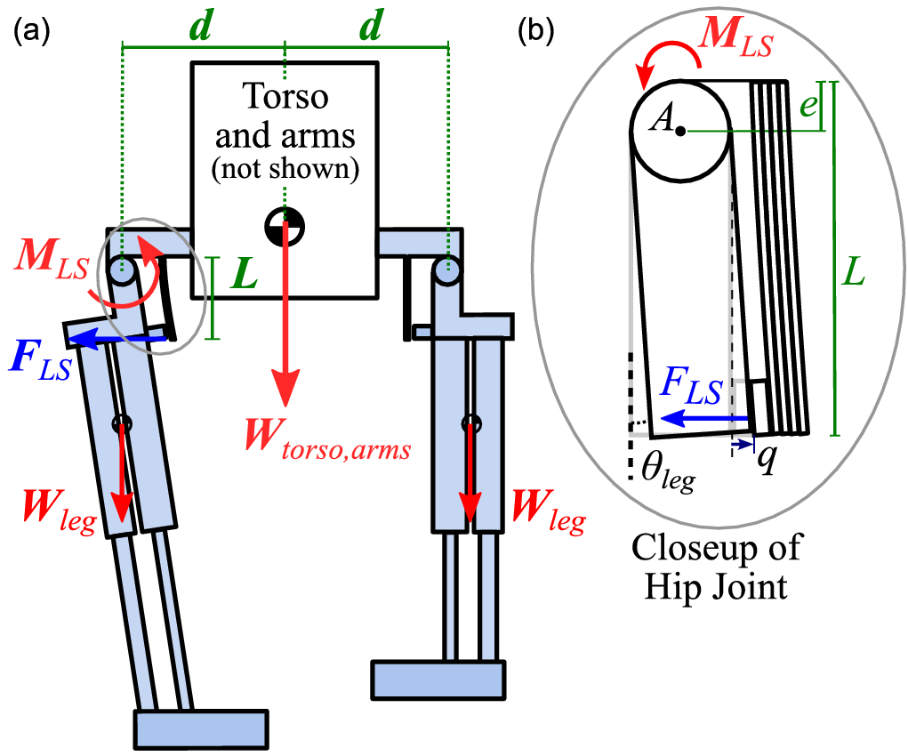


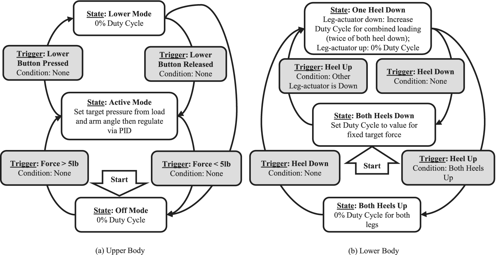
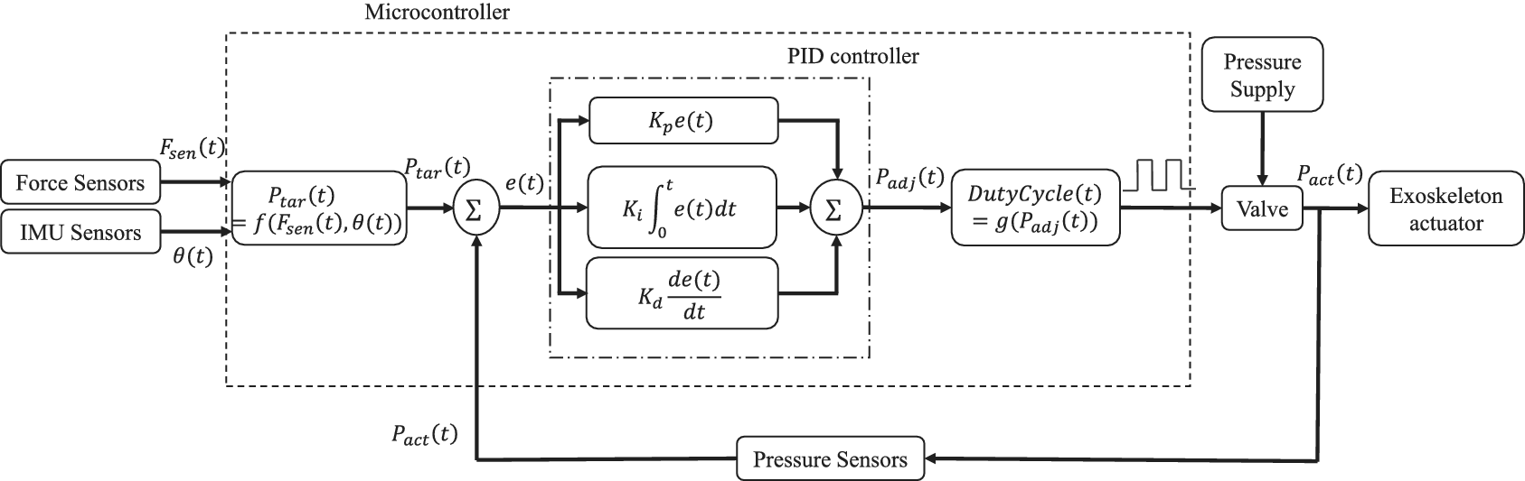


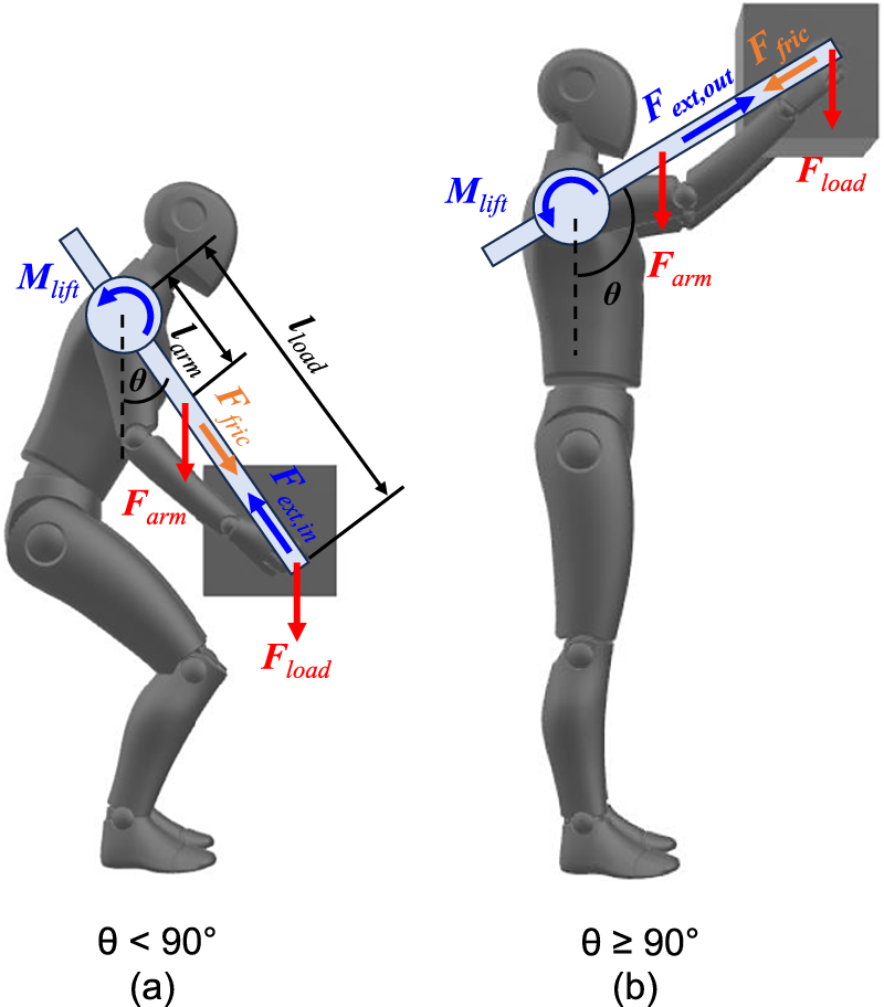


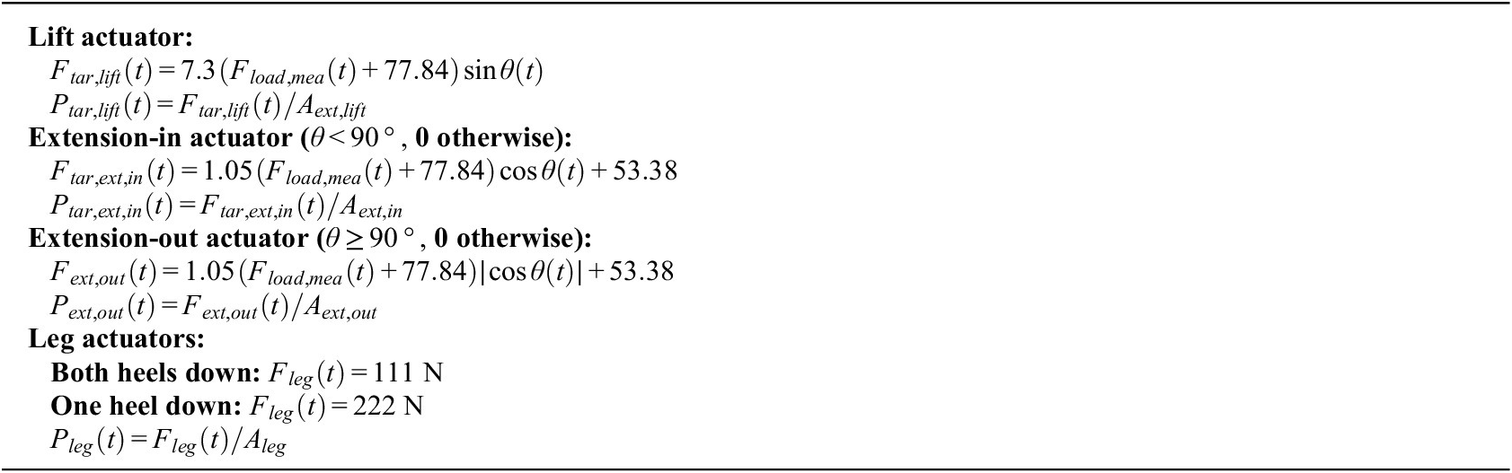


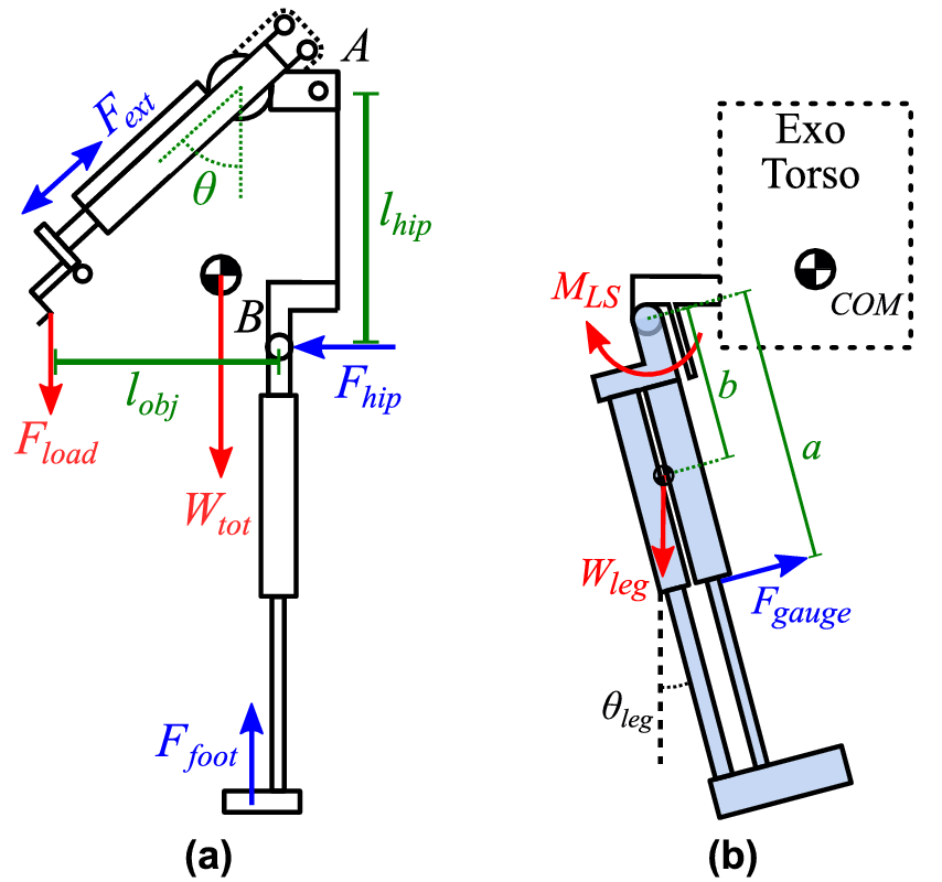



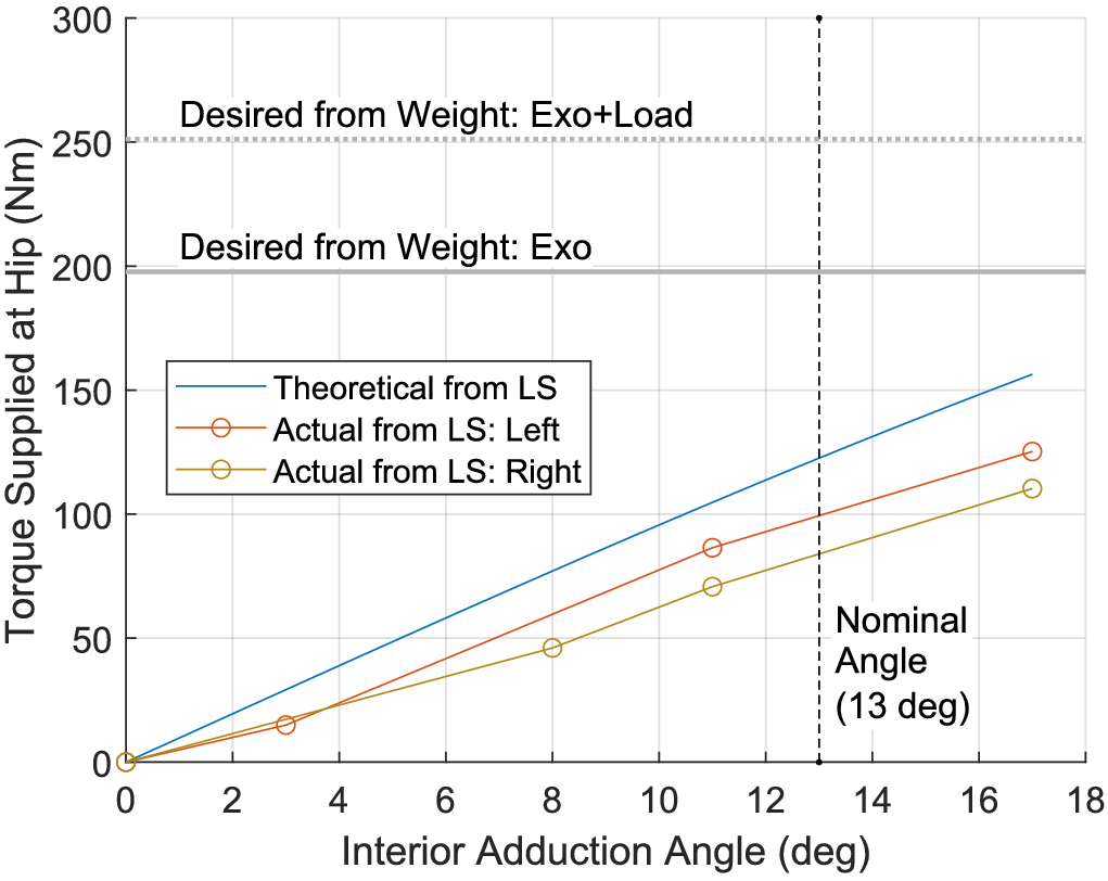


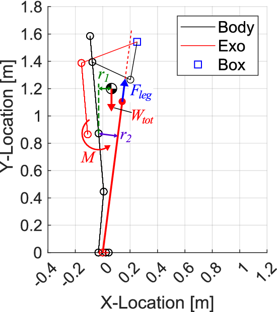


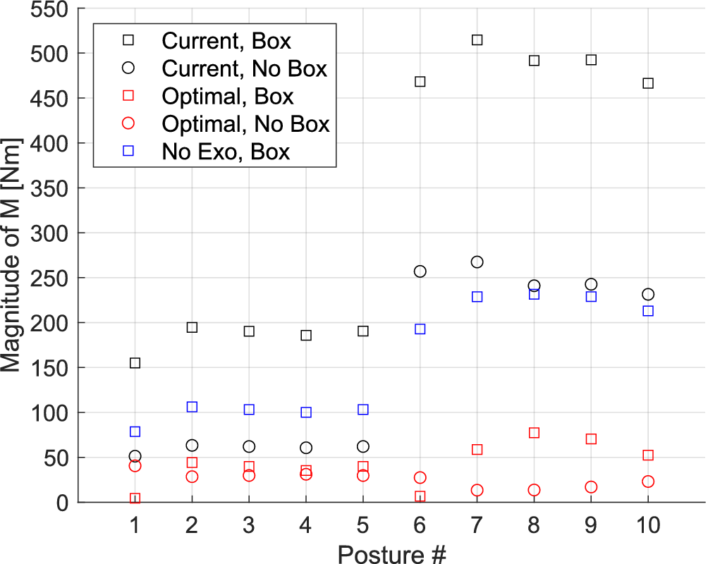
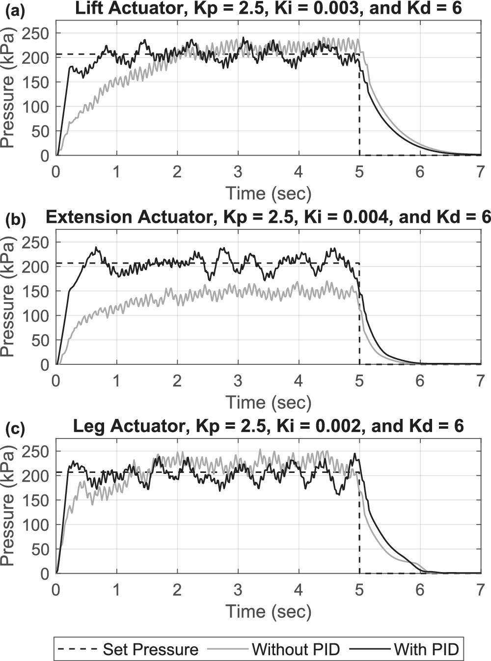


 Open access

