


I. INTRODUCTION
Currently, below 1% of the world's total car stock is equipped with driver assistance functions based on radar. Results from market research institutes indicate that the radar penetration rate could reach 50% in the year 2030 [Reference Kunert, Meinel, Fischer and Ahrholdt1]. This market trend brings interference between automotive radars back into the focus of research. Hischke addressed this topic in 1995 [Reference Hischke2] by simulations, which considered representative traffic densities and focussed on collision warning radars. An important observation was that the most important (closest) targets were never lost, but it was nevertheless summarized that the interference problem must be already considered during the process of system design. In 1997, a frequency modulated continuous wave (FMCW) interference-resistance policy was proposed by Tullsson [Reference Tullsson3]. He pointed out that a combination of narrow antenna beams, an elimination of interference by filtering in time or frequency domain, as well as a robust tracking process are necessary for an automotive radar system to be reliable. Oprisan [Reference Oprisan and Rohling4] presented the results of practical tests in 2005 and concluded, beside rules of thumb, that for their measurement setups interference by single radar was not a problem for the overall system functionality. In 2007, Brooker concluded [Reference Brooker5], based on analytical calculations, simulations and measurements that interference between FMCW radars results in a significant and continuous decrease in the signal-to-noise ratio (SNR). Subsequently to these publications, Goppelt [Reference Goppelt, Blöcher and Menzel6] did a more thorough investigation of interference between frequency modulated (FM) radars. Starting from 2010 practical tests, analyses and simulations were performed within the MOSARIM project to get an overview of the actual interference situation between automotive radars. After the end of this project research is still continued [Reference Braun, Tanbourgi and Jondral7–Reference Schipper, Mahler, Harter, Reichardt and Zwick9]. Furthermore simulation tools to estimate future interference situations between automotive radars are being developed [Reference Reichardt, Maurer, Fügen and Zwick10–Reference Schipper, Prophet, Zwirello, Harter, Reichardt and Zwick12]. This work extends the paper [Reference Schipper, Mahler, Harter, Reichardt and Zwick9], whereby its structure is as follows.
Section II estimates the operating range of FM radars and defines three different kinds of characteristic constellations for radar, target, and interferer. Depending on the radar's parameters and its gain versus interference the scenarios which are of interest can be identified.
In Section III, the factors which influence the above-mentioned gain versus interference are discussed in more detail. Further the shape of interference effects due to different kinds of disturbing waveforms is demonstrated for a FMCW radar by means of measurements.
II. OPERATING RANGE OF FM-RADARS IN THE PRESENCE OF INTERFERENCE
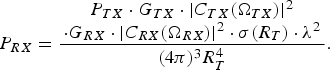
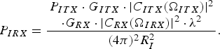
To roughly estimate the operating range of a radar in the presence of interference, a simple signal-to-interference (S/I) model can be derived from the radar (1) and the path-loss equation (2). It is assumed that the perturbed radar and the disturbing radar share the same carrier frequency range. For reasons of simplicity the perturbed radar is called “victim” and the disturbing radar is called “interferer” in the further text. If vehicles are no point targets for frequencies at 24 or 77 GHz, the radar cross-section (RCS) σ is a function of the distance between the victim and the target. To indicate this, σ is written as a function of the distance. The multi-path propagation, clutter and noise are not considered in the following
 $$P_{RX}=\displaystyle{\matrix{P_{TX} \cdot G_{TX} \cdot \vert C_{TX} \lpar \Omega _{TX} \rpar \vert ^2 \cr \cdot G_{RX} \cdot \vert C_{RX} \lpar \Omega _{RX} \rpar \vert ^2 \cdot \sigma \lpar R_T \rpar \cdot {\rm \lambda }^2} \over \lpar 4\pi \rpar ^3 R_T^4}.$$
 $$P_{IRX} = \displaystyle{\matrix{P_{ITX} \cdot G_{ITX} \cdot \vert C_{ITX} \lpar \Omega _{ITX}\rpar \vert^2 \cr \cdot G_{RX} \cdot \vert C_{RX} \lpar \Omega_{IRX}\rpar \vert^2 \cdot {\rm \lambda }^2} \over \lpar 4\pi\rpar ^2 R_I^2}.$$
 $$\displaystyle{P_{RX} \over P_{IRX}} = \displaystyle{\matrix{P_{TX} \cdot G_{TX} \cdot \vert C_{TX} \lpar \Omega_{TX}\rpar \vert^2 \cr \cdot \vert C_{RX} \lpar \Omega_{RX}\rpar \vert^2 \cdot \sigma \lpar R_T\rpar \cdot R_I^2} \over \matrix{P_{ITX} \cdot G_{ITX} \cdot \vert C_{ITX} \lpar \Omega_{ITX}\rpar \vert^2 \cr \cdot \vert C_{RX} \lpar \Omega_{IRX}\rpar \vert^2 \cdot 4\pi \cdot R_T^4}} = \displaystyle{S \over I}.$$
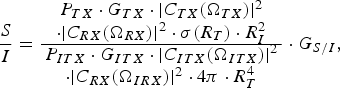
Equation (3) gives the S/I ratio at the receive antenna port of the victim. The capital letters P, G, and C denote the power at an antenna port, the gain of an antenna and the antenna's beam pattern. The indices of P, G, and C show the belonging to the transmit or receive side of the victim (TX and RX) or the transmit side of the interferer (ITX). The angles of outgoing radio waves are denoted by ΩTX for the transmit antenna of the victim and ΩITX for the transmit antenna of the interferer. The angles of incoming radio waves at the victim receive antenna are denoted by ΩRX for the useful signal and ΩIRX for the disturbing signal. R T is the distance from the victim to a target with the radar cross-section σ(R T) and R I is the distance from the interferer to the victim. The S/I-ratio does not include any gain by analog or digital processing yet.
The gain in S/I for a FM waveform based radar versus uncorrelated interference is
 $$G_{S/I} = B_V \cdot T_V\comma \; $$
where B V is the occupied signal bandwidth and T V is the duration of the victim's frequency ramp, which we assume is equal to the coherent processing time [Reference Pace13]. G S/I is also equal to the gain by ideal coherent pulse compression. Later, it will be shown that for the FMCW radar G S/I is achieved by a combination of analog filtering and a fast Fourier transform (FFT). Equation (3) can now be extended by this gain to
 $$\displaystyle{S \over I} = \displaystyle{\matrix{P_{TX} \cdot G_{TX} \cdot \vert C_{TX} \lpar \Omega_{TX} \rpar \vert^2 \cr \cdot \vert C_{RX} \lpar \Omega _{RX} \rpar \vert^2 \cdot \sigma \lpar R_T \rpar \cdot R_I^2} \over \matrix{P_{ITX} \cdot G_{ITX} \cdot \vert C_{ITX} \lpar \Omega _{ITX} \rpar \vert ^2 \cr \cdot \vert C_{RX} \lpar \Omega _{IRX} \rpar \vert ^2 \cdot 4\pi \cdot R_T^4}} \cdot G_{S/I}\comma \;$$
and rearranged to
 $$R_I = \sqrt{\displaystyle{S \over I} \cdot \displaystyle{\matrix{P_{ITX} \cdot G_{ITX} \cdot \vert C_{ITX} \lpar \Omega_{ITX} \rpar \vert ^2 \cr \cdot \vert C_{RX} \lpar \Omega _{IRX} \rpar \vert ^2} \over \matrix{P_{TX} \cdot G_{TX} \cr \cdot \vert C_{TX} \lpar \Omega _{TX} \rpar \vert ^2 \cdot \vert C_{RX} \lpar \Omega _{RX} \rpar \vert ^2}} \cdot \displaystyle{4\pi R_T^4 \over \sigma \lpar R_T \rpar \cdot G_{S/I}}}.$$
Assuming that the target and the interferer are within the victim's main beam and the victim is within the main beam of the interferer, (6) can be estimated by
 $$\eqalign{R_{I_S} &= \sqrt{\displaystyle{S \over I} \cdot \displaystyle{P_{ITX} \cdot G_{ITX} \over P_{TX} \cdot G_{TX}} \cdot \displaystyle{4\pi R_T^4 \over \sigma \lpar R_T \rpar \cdot G_{S/I}}} \cr &= \sqrt{\displaystyle{S \over I} \cdot \displaystyle{P_{IEIRP} \over P_{EIRP}} \cdot \displaystyle{4\pi R_T^4 \over \sigma \lpar R_T \rpar \cdot G_{S/I}}}.}$$
It is further assumed that both victim and interferer have the same equivalent isotropically radiated power (EIRP) and the targets are always in the far field (σ ≠ f(R T)). Automotive relevant objects in the far field could be bicycles or motor scooters for the view from behind. The RCS of motor scooters and bikes are (partially significantly) smaller than 10 dBsm, cars or trucks are usually around 15 dBsm and above for the most important aspect angles in the 24 GHz range [Reference Schipper, Fortuny-Guasch, Tarchi, Reichardt and Zwick14], whereas the RCS of pedestrians is significantly lower (about −7 to −3 dBsm) [Reference Fortuny-Guasch and Chareau15].
Based on equation (7) an equipotential line for a desired S/I-ratio in frequency domain can be drawn. This is done in Fig. 1 for the parameters listed in its caption and a variable distance between radar and target.
The area above the blue (diagonal) line includes all victim/target/interferer constellations where a S/I of 10 dB or better is likely. S/I = 10 dB; GS/I = 52 dB; PIEIRP = PEIRP; σ = 10 dBsm ≠ f(RT).

The blue (diagonal) line in Fig. 1 represents the constellations of victim, target, and interferer which lead to the desired S/I-ratio (here 10 dB). This line divides the area into two sections. The upper section corresponds to constellations which fulfill the desired S/I-ratio. This upper section is named IFOC, indicating interference free operation constellations.
The lower section corresponds to constellations which do not fulfill the desired S/I-ratio. This lower section is named TMC, indicating target masking constellations.
But a radar cannot only loose targets (or peaks in the spectrum) due to interference by radars in near vicinity. The target itself also disturbs the victim, if the target is equipped with radar sensors. As a result the interference floor raises and from a certain distance on the target falls below the constant-false-alarm-threshold of the victim. The distance from which this occurs is named the target self-masking distance (TSMD) here.
The equipotential lines for different values of G S/I, a fixed σ and a fixed S/I are drawn in Fig. 2. Based on the estimation, e.g. a 0 dBsm target in 30 m distance could fall below the wanted S/I of 10 dB if an interferer is present within 10 m radius from the radar.
Operating ranges for different G S/I. S/I = 10 dB; PIEIRP = PEIRP; σ = 10 dBsm ≠ f(RT).
The TSMD for a car is very high, so it is highly unlikely to loose cars as a result to interference by themselves. Cars in near vicinity could mask vehicles far away, but normally the closest targets are most important for the assistance function. But nevertheless the maximum detection range of all radars is decreased if interference is present and the scenario is not clutter and not yet noise limited. If a smaller target like a motor bike would have a radar and a RCS of 0 dBsm for the front view, the TSMD starts at 90 m for a G S/I of 60 dB according to Fig. 2. Therefore, if the scenario is not yet limited by clutter, this could lead in a later detection of the fast approaching target. The hard separation between IFOC and TMC is valid for the assumptions made so far. In reality, the S/I-ratio fluctuates. The reason therefore, among others, is fading caused by multipath effects and a variable gain versus interference G S/I.
In the following section factors, which influence the gain versus interference G S/I, are discussed.
III. BASIC MECHANISM OF INTERFERENCE BETWEEN FM RADARS
The frequency ramp of a victim with FMCW modulation including its anti-aliasing filter (AAF) is presented in an idealized spectrogram in Fig. 3. Further CW and FMCW interferers, which pass the FMCW's AAF and lead to unwanted mixer output frequencies are sketched.
The areas around the crossing ramps show beat frequencies in a FMCW receiver resulting from a FMCW and a CW interferer, respectively. The beat frequencies are drawn relatively to the victim's frequency ramp.
Measurements in the anechoic chamber demonstrate the resulting interference effects from a CW signal onto a FMCW radar with eight receive channels and digital beamforming capabilities [Reference Harter, Schipper, Zwirello, Ziroff and Zwick16, Reference Harter, Ziroff and Zwick17]. The spike in time domain (Fig. 4) marks the moment when the disturbing signal is within the AAF's passband.
In time domain all eight receive channels show a rather similar spike due to interference by a CW interferer.
The Fourier transform turns this spike into a broadband increase of the interference level in frequency domain for all eight receive channels (Fig. 5). Also the direction from which the disturbance comes from, as well as the interferer itself is visible after beamforming (Fig. 6). In an environment without strong fading effects equation (7) could be further used to estimate the distance to an interferer based on the observed interference floor.
The interference floor is far above the radar's noise level in frequency domain.
The source which causes this reduction of the dynamic range can be seen at a distance of about 6 m. It has an output power of 20 dBm EIRP.
The increase of the interference level in time domain is proportional to the dwell time of interference in the victim's AAF. The dwell time is now further discussed.
A) Dwell time of interference
Referring to Fig. 3 an ideal rectangular filter changes the mean received interference power P IRX from the CW signal due to a duty cycle and a gain by the number of computed FFT points as it was already stated in [Reference Oprisan and Rohling4]:
 $$P_{IF} \approx P_{IRX} \cdot \displaystyle{t_{dCW} \over T_{obs}} \cdot \displaystyle{1 \over N_{FFT}} = P_{IRX} \cdot \displaystyle{2 \cdot B_{AAF} \over B_V} \cdot \displaystyle{1 \over N_{FFT}}\comma \;$$
where P IF is the interference power in a frequency bin after the FFT. If the sampling theorem is fulfilled this equation can be simplified to
 $$\eqalign{P_{IF} &= P_{IRX} \cdot \displaystyle{2 \cdot B_{AAF} \over B_V} \cdot \displaystyle{t_s \over T_V} = P_{IRX} \cdot \displaystyle{2 \cdot B_{AAF} \over B_V} \cr &\quad \cdot \displaystyle{1 \over 2 \cdot B_{AAF} \cdot T_V} = \displaystyle{P_{IRX} \over B_V \cdot T_V}\comma \; }$$
where t s is the sampling time. As it can be recognized in (8) and (9) the ideal gain B V·T V is realized by a combination of analog filtering and a FFT. Oversampling does not ensure the regain of dynamic range in the presence of interference by deterministic signals.
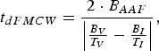
In case of another FMCW interferer (also referring to Fig. 3) the dwell time of interference is changed. The new dwell time (10) is dependent on the frequency slope of the chirp created by the mixing of the signals from victim and interferer
 $$t_{dFMCW} = \displaystyle{2 \cdot B_{AAF} \over \left\vert {B_V \over T_V} - {B_I \over T_I} \right\vert}\comma \;$$
where falling chirps have negative signs and rising chirps have positive signs. We can express this change of the ideal gain B V·T V from the case of CW interference to a FMCW interference by a scaling factor
 $$SF = \displaystyle{t_{dCW} \over t_{dFMCW}} = \displaystyle{2 \cdot B_{AAF} \over \left\vert {B_V \over T_V} \right\vert} \cdot \displaystyle{\left\vert {B_V \over T_V} - {B_I \over T_I} \right\vert \over 2 \cdot B_{AAF}} = \displaystyle{\left\vert {B_V \over T_V} - {B_I \over T_I} \right\vert \over \left\vert {B_V \over T_V} \right\vert}.$$
The ideal gain can then be modified to
 $$G_{S/I} = B_V \cdot T_V \cdot SF. $$
In [Reference Goppelt, Blöcher and Menzel6], this principle behavior was also derived from the view of dwell time per frequency bin and measured for a combination of up and down chirp.
In order to enhance G S/I it can now be thought of maximizing the SF by further increasing one of the involved chirp's slope. Because the bandwidth is limited by regulation, only the chirp time can be further reduced. As a consequence the chirp repetition rate must be increased to ensure a certain doppler resolution (dependent on coherent processing time) and to maintain a high G S/I. So a shorter dwell time of interference is traded for more frequent moments of interference and the mean level of interference stays the same.
A better possibility would be to use chirps with the same (or full) bandwidth and different slope signs. Forward looking radars could, e.g. drive up-chirps and backward looking radars down-chirps. This effectively reduces the dwell time of interference.
What is not considered yet is the effect of windowing in time domain before the FFT.
B) Windowing
The windowing ensures the control over resolution and dynamic range by a time dependent damping of the signal. In average this damping influences signal and interference, if the interference-spikes are uniformly distributed in time (within one chirp or one spike in several chirps). If interference happens mainly in a certain region, let us say for example in the middle of a chirp, the interference-spike is not damped but the signal is. This leads to an additional loss in the overall S/I, which is approximately the coherent power gain of the window in that case. In contrast, the windowing can also increase the overall S/I if the reduction of the interference-spike in time domain is larger than the coherent gain of the window. Figures 7 and 8 demonstrate these effects by terms of measurement (maximum observed interference in population is shown).
The window will mainly suppress the interference localized near the boundaries of a time domain signal.
The interference floor in frequency domain can be heavily dependent on windowing.
The effective CW interference is strongly dependent on its position in time. If interference is localized only a few samples around a sample n, the gain in S/I by a normalized window win is
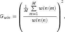 $$G_{win} = {\left(\displaystyle{{1 \over M} \sum\limits_{m = 1}^M win\lpar m\rpar \over win\lpar n\rpar } \right)}^2\comma \;$$
where by M is the length of win. This formula is closely related to the processing gain of a window as it is presented in [Reference Harris18].
That indicates that narrow band waveforms at the outer boundary of the available spectrum, have only a small effect on broadband, FM waveforms which perform windowing before the FFT.
If a FMCW radar is interfered by a foreign (FM)CW waveform, the phase relation of these waveforms is of special interest. The role of this phase relation will be discussed in the next subsection.
C) Influence of phase relation
Mixing two ideal linear frequency ramps with different slopes (see Fig. 3) results in another linear frequency ramp (14) with the differences of the previous chirps' parameters as new parameters
 $$s\lpar t\rpar = \cos \left(2\pi \lpar f_{b2} - f_{b1} \rpar t + \pi \lpar \mu _2 - \mu _1\rpar t^2 + \lpar \varphi_2 - \varphi_1\rpar \right). $$
or
 $$s\lpar t\rpar = \cos \lpar 2\pi \Delta f_b t + \pi \Delta \mu t^2 + \Delta \varphi\rpar .$$
The initial frequencies and phases of the frequency ramps are denoted by f b and φ whereas the ramp slopes are denoted by μ in Hz/s. Their differences are labeled by Δf b, Δμ, and Δφ. Splitting equation (15) into two exponential functions and using the following Fourier correspondence
 $${\cal F}\left\{\exp \lpar jxt^2\rpar \right\}= \sqrt{\displaystyle{\pi \over x}} \exp \left(- j\left(\displaystyle{\omega^2 \over 4x} - \displaystyle{\pi \over 4} \right)\right)\comma \;$$
the following expression can be derived:
 $$S\lpar f\rpar = \displaystyle{1 \over \sqrt{\left\vert \Delta \mu \right\vert}} {\rm e}^{\left(j{2\pi f\Delta f_b \over \Delta \mu} \right)} \cos\left(\displaystyle{\pi f^2 \over \Delta \mu} + \displaystyle{\pi \Delta f_b^2 \over \Delta \mu} - \Delta \varphi - \displaystyle{\pi \over 4} \right)\comma \;$$
with Δμ ≠ 0. Equation (17) consists of three separable parts. The exponential part includes the time delay which corresponds to the point in time where the frequency ramps cross each other. The scaling factor dependent upon Δμ shows that the more correlated two radar signals are (e.g. the smaller the difference in frequency slopes is), the higher the resulting interference floor is. The sinusoidal part describes the general form of the spectrum which shows again a ramp like characteristic.
If the first null of (17) occurs at a frequency higher than the maximum acceptable beat frequency (which normally corresponds to the cutoff frequency of an AAF), the height of the spectrum can be approximated as flat within the filter bandwidth. The phase relation Δφ varies directly the spectrum's height by a factor of
 $$G_\varphi = \left\vert \cos \left(\displaystyle{\pi \Delta f_b^2 \over \Delta \mu} - \Delta \varphi - \displaystyle{\pi \over 4} \right)\right\vert.$$
This can be observed in Fig. 9, which shows a simulated scenario in the complex baseband in comparison with the measurement of synthetic radar signals at 880 MHz, down-converted into baseband with a mixer. The measurements were done at a center frequency of 880 MHz and not 24 or 77 GHz, so the signals for feeding the mixer can directly be generated by an arbitrary waveform generator with 12 giga-sample-per-second.
The phase relation between the victim's and interferer's local oscillator can rapidly change the level of the interference floor.
A victim FMCW radar with a positive Δμ (150 MHz bandwidth, 1.5 ms transmit time for the simulation and 20 MHz bandwidth, 200 µs transmit time for the measurement resulting in the same frequency slope for simulation and measurement) is interfered by a CW interferer located in the middle of the respective bandwidth. The three disturbing signals inherit a phase difference Δφ of −π/6, −π/2 and −11π/18 relative to the victim signal, resulting in a calculated damping of respectively 0.3, 3, and 7.5 dB.
It is worth mentioning that the lower the null in frequency domain, the less valid is (18). But at the same time the height of the spectrum is decreased and thus the interference is more and more negligible.
Since in many cases of interference, above-mentioned approximation is valid, the resulting impulse in time domain matches the scaled impulse response of the AAF. The scaling occurs according to the damping caused by phase relation and other influences like windowing and the scaling factor in (11).
D) I/Q-receiver
Using an in-phase and quadrature components (I/Q)-receiver will have two important consequences for the interfered spectrum. The fluctuating interference floor resulting from a certain phase relation disappears due to the complex superposition of the in-phase and quadrature components. This results in a flat interference floor, as can be observed in Fig. 10. The same setups were used as described for Fig. 9. The phase delay of π/2 between I and Q channels can be observed here as well.
Instead of a fluctuating interference floor due to a single FM interference the I/Q-receiver provides a stable floor at −6 dB with respect to the highest floor due to the absence of an I/Q-receiver.
As a result of this flat interference floor the interfering signal in time domain will always represent the impulse response of the used low-pass filter and not only for certain phase relations. Thus the resulting interference floor and the impulse in time domain are well predictable while at the same time any potential gain caused by a propitious phase relation is lost.
Furthermore, using an I/Q-receiver will increase the S/I-ratio by up to 6 dB, due to a distinction between positive and negative beat frequencies caused by interferers. This increase in S/I is shown in Fig. 10.
E) The summarized gain versus interference by a single interferer
Summarizing the previous sections the total gain versus interference for a FMCW radar versus another FMCW radar for one intersection can be given:
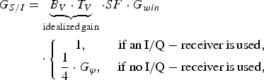 $$\eqalign{G_{S/I} &= \underbrace{B_V \cdot T_V}_{{\rm idealized\, gain}} \cdot SF \cdot G_{win}\cr &\quad \cdot \left\{\matrix{1\comma \; & {\rm if\, an\, I}/{\rm Q} - {\rm receiver\, is\, used}\comma \; \cr \displaystyle{1 \over 4} \cdot G_\varphi\comma \; &{\rm if\, no\, I}/{\rm Q} - {\rm receiver\, is\, used}\comma \; } \right.}$$
where SF is the scaling factor as introduced by (11) and G win is the effective gain by windowing. G φ is the gain due to the phase relation between victim and interferer as it is described in (18).
F) Shape of interference in a FMCW receiver due to different waveforms
In frequency domain CW interference shows up as a smooth, uniform increase of the interference floor (Fig. 11), which is fluctuating from ramp to ramp due to the phase relation as described in Section IIIC). It is quite different if interference happens more often within one victim chirp, as it is the case for interference by a frequency shift keying (FSK), fast FMCW or chirp sequence (CS) waveform (Fig. 11). It is getting less likely that no interference spike in time domain (Fig. 12) is visible due to optimum phase relation, what causes a more stable interference floor from ramp to ramp. Furthermore, the interference floor is not smooth any more, because interference occurs in a series of pulses, which lead to deterministic bows in frequency domain. All data are plotted for one interferer. For estimating the effect of multiple interference, the contributions of several radars can be summed up incoherently, regarding the mean value.
Interference by a FSK waveform causes wide bows in frequency domain. Interference by a CS waveform leads to a noisy interference floor. For comparison the CW interference is plotted, too.
The CS waveform causes a higher number of spikes in time domain, but with smaller amplitudes due to a shorter dwell time within the filter in comparison to a CW or FSK interferer. The FSK waveform causes several stronger interference spikes in a short period of time.
IV. CONCLUSION
The operating range of radars in the presence of interference can be estimated based on the model presented here. Furthermore, a perturbed radar cannot only loose a target due to interference from other radars in near vicinity. For example, a target equipped with a radar and a RCS of 10 dBsm could hide itself temporarily from the perturbed radar, starting above ≈90 m distance for a total G S/I of 50 dB (see Fig. 2).
Furthermore it was shown that interference by other radars cannot be considered as white noise and that different types of waveforms lead to a different shaping of the frequency domain data. The use of an I/Q-receiver in a FMCW radar leads to a 6 dB lower maximum interference floor in comparison to a FMCW radar without I/Q-receiver due to the superposition of positive and negative beat frequencies. In contrast, if no I/Q-processing is performed, the radar can possibly profit from beneficial phase relations between its own and the interfering signal. This can lead temporarily to a significantly lower increase of the interference floor than in the case of I/Q-processing.
A windowing before the FFT in broadband FM radars suppresses narrow band interference at the outer boundaries of the available spectrum.
ACKNOWLEDGEMENTS
The research leading to these results has received funding from the European Community's Seventh Framework Programme (FP7/2007-2011) under grant agreement no. 248 231 – MOSARIM Project.
Tom Schipper received his Dipl.-Ing. (FH) degree in communications and electronic engineering from the University of Applied Sciences Mannheim, Germany in 2008 and 1 year later, he received the M.Sc. degree in information technology from the same institution. He is currently working toward his Dr.-Ing. (Ph.D.) degree at the Institut für Hochfrequenztechnik und Elektronik (IHE) at the Karlsruhe Institute of Technology in the field of radar interference, system simulations and automotive radar.
Marlene Harter received the Dipl.-Ing. (M.S.E.E.) degree in electrical engineering from the Universität Karlsruhe (TH), Germany in 2008. She is currently working toward her Dr.- Ing. (Ph.D.) degree at the Institut für Hochfrequenztechnik und Elektronik (IHE) at the Karlsruhe Institute of Technology in cooperation with Siemens AG in Munich, Germany. Her main research interests are radar signal processing as well as radar system design and concepts for industrial applications.
Tobias Mahler received his Master of Engineering degree in Communications Engineering and Information Technology from the University of Applied Sciences Karlsruhe, Germany in 2011. He is currently working toward his Dr.-Ing. (Ph.D.) degree at the Institut für Hochfrequenztechnik und Elektronik (IHE) at the Karlsruhe Institute of Technology in the field of multiple antenna systems and mobile communications.
Oliver Kern received his Bachelor of Engineering degree in 2011 at Baden-Wuerttemberg Cooperative State University while working at Robert Bosch GmbH on different projects regarding driver assistance systems and signal processing. He is currently working on his master thesis at Karlsruhe Institute of Technology (KIT).
Thomas Zwick (S’95-M’00-SM’06) received the Dipl.-Ing. (M.S.E.E.) and the Dr.-Ing. (Ph.D.E.E.) degrees from the Universität Karlsruhe (TH), Germany, in 1994 and 1999, respectively. From 1994 to 2001, he was a research assistant at the Institut für Höchstfrequenztechnik und Elektronik (IHE) at the Universität Karlsruhe (TH), Germany. In February 2001, he joined IBM as research staff member at the IBM T. J. Watson Research Center, Yorktown Heights, NY, USA. From October 2004 to September 2007, Thomas Zwick was with Siemens AG, Lindau, Germany. During this period, he managed the RF development team for automotive radars. In October 2007, he became a full professor at the Karlsruhe Institute of Technology (KIT), Germany. He is the director of the Institut für Hochfrequenztechnik und Elektronik (IHE) at the KIT. He is author or co-author of over 200 technical papers and 20 patents. His research topics include wave propagation, stochastic channel modeling, channel measurement techniques, material measurements, microwave techniques, millimeter wave antenna design, wireless communication, and radar system design.



