Introduction
A reflectarray antenna has evolved as an alternative to the parabolic reflector in applications where planarity, beam switching, and frequency reconfiguration are of prime importance [Reference Shaker, Chaharmir and Ethier1]. It is realized by combining the features of both phased array antenna and parabolic reflector. However, reflectarray antennas suffer from narrow bandwidth, which is predominantly due to the non-linear reflection phase response of the elements in the case of small- and medium-sized reflectarray antennas [Reference Borgese, Costa, Genovesi and Monorchio2–Reference Chaharmir, Shaker, Gagnon and Lee4]. This shortcoming has motivated antenna researchers to propose numerous methods for achieving linear and wider dynamic phase ranges and less phase variation as a function of frequency [Reference Shaker, Chaharmir and Ethier1–Reference Chaharmir, Shaker, Gagnon and Lee4]. The techniques that have been reported to achieve wideband performance of the reflectarray are (i) use of thick substrate [Reference Shaker, Chaharmir and Ethier1], (ii) use of multi resonant [Reference Borgese, Costa, Genovesi and Monorchio2, Reference Zhong, Chen, Shi and Shi3] and sub-wavelength [Reference Delafkar and Phirhadi5] elements, (iii) optimization [Reference Chaharmir, Shaker, Gagnon and Lee4], (iv) multilayer configuration [Reference Encinar, Florencio, Arrebola, Natera, Barba, Page, Boix and Toso6], (v) true time delay (TTD) [Reference Delafkar and Phirhadi5], and (vi) shared aperture [Reference Chen, Chen, Wang, Gu and Shi7]. The first two methods are easy to employ and have been implemented for more than a decade [Reference Shaker, Chaharmir and Ethier1–Reference Zhong, Chen, Shi and Shi3]. The optimization technique alters the reflection phase performance of the element such that linear phase response is obtained, which in turn can lead to less phase variation as a function of frequency [Reference Shaker, Chaharmir and Ethier1, Reference Chaharmir, Shaker, Gagnon and Lee4]. While multilayer configurations have been investigated for several years, they offer wideband performance at the cost of increased dielectric and conductor losses and design complexity [Reference Shaker, Chaharmir and Ethier1, Reference Encinar, Florencio, Arrebola, Natera, Barba, Page, Boix and Toso6]. The above bandwidth enhancement techniques are most suited for small- and medium-size reflectarrays. However, for a large-size reflectarray the required phase distribution varies significantly as a function of frequency due to the spatial delay dispersion. To overcome this challenge and thereby to attain wideband performance for such arrays, a TTD technique has been employed along with the above [Reference Delafkar and Phirhadi5]. The shared aperture technique encompasses methods (i) and (ii) and the principle of frequency selective surfaces. This technique is used to accomplish multi-frequency and multi-band operations [Reference Zhong, Chen, Shi and Shi3, Reference Chen, Chen, Wang, Gu and Shi7]. In general, a combination of methods (i) and (ii) is being investigated by several researchers, as the approach is less complex compared to other three techniques. Following such an approach, various unit cell designs have been reported for the enhancement of reflectarray antenna bandwidth. Among them, the elements based on cross-dipole are broadly employed for the wideband reflectarray design [Reference Chen, Chen, Wang, Gu and Shi7–Reference Hamzavi-Zarghani and Atlasbaf11]. Some of the structures reported within this category include simple cross dipole [Reference Chen, Chen, Wang, Gu and Shi7, Reference Hamzavi-Zarghani and Atlasbaf11], multi cross loops [Reference Chaharmir, Shaker, Gagnon and Lee4], stub loaded cross dipole [Reference Lingasamy, Selvan and Jyoti8], double cross loops [Reference Chaharmir, Shaker, Cuhaci and Ittipiboon9], modified cross loop element [Reference Wang, Shao, Li, Li and Cheng10], Jerusalem cross-shaped slot loaded patch with ring [Reference Hamzavi-Zarghani and Atlasbaf11], and cross dipole with double ring elements [Reference Lingasamy, Alsath, Selvan and Jyoti12]. These elements offer a wideband performance; however, the dynamic reflection phase range is still limited to about 550°. Thus, from above studies, it is evident that the improvement of reflection phase range for attaining larger radiation bandwidth continues to be of research interest among the antenna community.
In this paper, a simple patch unit cell loaded with square ring and cross loop slots is proposed for large reflection phase and wide radiation bandwidth. The proposed unit cell is a simplified version of the one reported in [Reference Hamzavi-Zarghani and Atlasbaf11]. The proposed reflectarray unit cell element exhibits a very wide reflection phase bandwidth without compromising the phase range of about 599° [Reference Lingasamy, Selvan and Jyoti8]. This performance enhancement is due to the multi-resonant nature of the element and the foam substrate loading. A wide and smooth reflection phase response is achieved by optimizing the thickness of the foam dielectric and geometrical parameters of the multi resonant element.
The rest of the manuscript is organized as follows. The design and analysis of a reflectarray using cross loop and square ring slot loaded patch elements is presented in the Section “Design and analysis of a wideband reflectarray with RT5880 substrate”. The radiation characteristics of the proposed reflectarray and comparison of its performance with the existing ones are illustrated in the Section “Results and Discussion”. The key outcomes of this study are summarized in the Section “Conclusion”. The simulation studies of elements and reflectarray system are performed using CST Microwave Studio 2017.
Design and analysis of a wideband reflectarray with RT5880 substrate
Element design
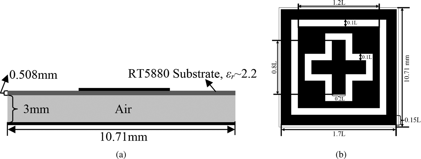
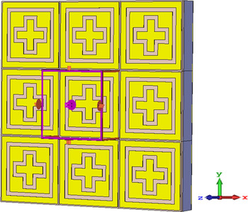
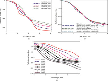
The geometry and evolution of cross loop and square ring slot loaded patch element are shown in Fig. 1 and Table 1, respectively. The unit cell design is initiated with an analysis of a simple square ring slot loaded patch, printed on a conductor-backed substrate of size 0.5λ 0 at 14 GHz as shown in Fig. 1(a). It is then analyzed for its reflection phase performance by using the infinite array/unit cell approach in CST Microwave Studio, as shown in Fig. 2. A phase bandwidth of 19% with a dynamic range of 512° is achieved, which is better than the one offered by the resonant microstrip patch. This is due to loading an appropriate slot in the square patch, which has the effect of widening the bandwidth [Reference Shaker, Chaharmir and Ethier1]. Another version of slot loading is tested by the microstrip patch with the crossed loop slot. This configuration offered a substantial improvement in bandwidth of about 48%. However, its dynamic reflection phase range is reduced to less than half that of the previous configuration i.e. to 238°, which is due to the wider reflection phase bandwidth [Reference Shaker, Chaharmir and Ethier1, Reference Chaharmir, Shaker, Gagnon and Lee4]. Thus, with a view to achieve a large reflection phase at the same time of obtaining a wider bandwidth, the single microstrip square patch is loaded with both the slots. Subsequently, reflection phase analysis is carried out by simulation. This proposed unit cell element offers a higher reflection phase range of 599° and a large bandwidth of 57%. The reflection phase range and the bandwidth offered by the resonant microstrip square patch loaded with square ring slot, crossed loop slot, and with both the slots are all presented Table 1. From this table it is evident that the proposed element offers a wider reflection phase range and bandwidth than the other configurations. In all the above studies, the thickness of the air or foam dielectric substrate is optimized to be 3 mm, which is based on the compromise between the bandwidth i.e. smooth phase response and the dynamic reflection phase range, as shown in Fig. 3(a). With this observation, the reflection phase performance of cross loop and square ring slots loaded patch as a function of geometrical length of the element is plotted in Fig. 3(b), at the frequency of 14 GHz.
Cross loop and square ring slot loaded patch configuration: (a) side view and (b) top view.

Infinite array approach-based unit cell simulation model in CST Microwave Studio.

Reflection phase performances of the cross loop and square ring slots loaded patch element as a function of its geometrical length (a) for various thicknesses of foam dielectric, (b) for TE and TM modes and different incident angles at 14 GHz, and (c) for various frequencies in X/Ku and Ku bands.

Evolution of the reflectarray unit cell element

Effect of modes and angle of incidence on reflection phase
The proposed unit cell element is examined for both TE and TM polarization modes with normal incidence by simulation. This is to see the effect of modes on its reflection phase, and to verify its polarization sensitivity. Both responses exhibit a good match because of the symmetric element geometry as evidenced in Fig. 3(b). Further, for a given focal point, the incident angle of the wave on the elements in the reflectarray varies as a function of their locations. This in turn results in variations in the reflection phase as well. In order to see the effect of incident angle on the phase of the element, the reflection phase is estimated for both TE and TM modes with different incident angles such as 0, 20, and 35° in both elevation (θ) and azimuth (ϕ) planes. These observed reflection phases are plotted as a function of the element length in Fig. 3(b). It is noticed that the reflection characteristics of the proposed element remain stable for an angle of incidence up to 35°, in both elevation and azimuth planes irrespective of the incident mode, with the acceptable phase deviation i.e. ±45° [Reference Shaker, Chaharmir and Ethier1]. A slight variation is observed for the element size of around 5.5 mm, which could be caused by mutual coupling between the elements. However, almost all sizes of elements that are used to construct reflectarray were below 5.5 mm, where the reflection phase performance is found to be stable. Therefore, this element can be used for constructing large, dual polarized, and offset-fed reflectarrays, where incident mode and angle of the element play a key role in phase compensation.
Estimation of reflection phase bandwidth
To obtain the bandwidth of the proposed element, reflection phase is estimated for various frequencies in X/Ku and Ku bands with the help of a simulation tool. These results are plotted as a function of the length of the element in Fig. 3(c). It is observed that for a given element length, the difference between reflection phases at the adjacent frequencies is within ±45° for most of the element sizes. Therefore, this element can be used to operate in the wide frequency range of 10–18 GHz.
Loss estimation
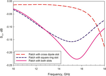
Reflection amplitude performances of the three configurations listed in Table 1 are estimated by simulation, which are then plotted as a function of frequency in Fig. 4. It is observed that the reflection loss of the patch loaded with square ring and cross dipole slots is slightly higher than that of the other two configurations. This is attributed to the broad band nature of the proposed element, where the higher losses are incurred due to increased bandwidth. This result reiterates the inverse relationship between bandwidth and Q factor [Reference Shaker, Chaharmir and Ethier1]. The maximum loss that is caused by the element is to be still less than 0.25 dB. This indicates that the proposed element can be used in realizing wideband and also low loss reflectarray.
Reflection loss performances of three configurations as a function of frequency.

Reflectarray realization
The compensation phase for the center-fed reflectarray of size 200 × 200 mm2 with 324 elements is calculated using equation (1) in [Reference Hamzavi-Zarghani and Atlasbaf11], at the frequency of 14 GHz. While estimating phase distribution, the feed location of (0, 0, 140 mm) and the beam direction of (θ b = 0°, ϕ b = 0°) are employed. Subsequently, the reflectarray is constructed with equally spaced cross loop and square ring slot loaded patch elements of varied geometrical lengths. The size of the reflectarray has been chosen based on the capacity of the Dell workstation, which is with a quad core Xeon processor and 64 GB RAM, available at the authors’ institute.
Reflectarray analysis
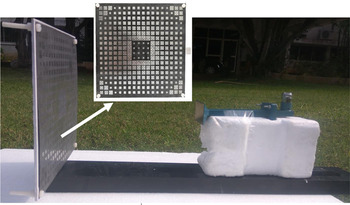
In order to analyze the above reflectarray, a Ku band optimum pyramidal horn is designed for the gain of 14 dB at 15 GHz [Reference Selvan13]. It is then examined for radiation characteristics by simulation, and the gain values are observed to be in the range of 10.8–14.6 dB in the frequency range of 10–18 GHz. Subsequently, phase center is estimated in that frequency range, and noticed a variation from 6 to 24 mm from the horn aperture [Reference Moharram and Kishk14]. And the feed illumination taper is noted as 8 dB at the design frequency. With the above horn used as feed, the reflectarray system is analyzed using CST Microwave Studio for its radiation characteristics. Subsequently, the optimal results are achieved for the focal length of 122 mm and an inter-element spacing of 10.6 mm. The optimized focal distance is different from the designed one, which could be due to the change in the phase center of the feed horn as a function of frequency as mentioned above, and effect of feed location on bandwidth performance of the reflectarray [Reference Huang15]. An optimal wideband reflectarray is fabricated, and the prototype is shown in Fig. 5. It is examined at the measurement facility at the authors’ institute, for radiation pattern and gain characteristics. Further, the cross-polarization level is measured by placing a transmitting antenna in the vertical polarization and the reflectarray antenna in the horizontal polarization and vice versa for H- and E-planes, respectively [Reference Keen and Brown16]. In order to estimate the gain of the proposed reflectarray antenna, the modified two antenna method is employed, where a standard gain pyramidal horn antenna is used as the transmitting antenna [Reference Selvan, Sharma, Mishra and George17]. The numerical and experimental radiation pattern and gain performances of the proposed reflectarray, and their comparison with the reported structures are discussed in the following section.
Fabricated prototype of the proposed 324 element reflectarray antenna.

Results and discussion
H-plane radiation patterns
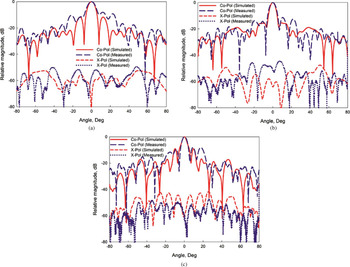
The estimated and normalized co- and cross-polarization radiation patterns in the H-plane of the reflectarray are shown in Figs 6(a)–6(c), at the frequencies of 10, 14, and 16.8 GHz. A better match is observed between both the co-polarization radiation patterns of the proposed reflectarray, and the measured 3-dB beam widths are noted to be 7, 5.4, and 4.8° at the frequencies of 10, 14, and 16.8 GHz, respectively. Further, the side lobe level of the proposed reflectarray antenna is lower than −10 dB as illustrated in Figs 6(a)–6(c). The measured co-polarization patterns do not display symmetry about the boresight direction, thus a slight deviation is perceived. Also, the experimentally estimated cross polarization does not correlate with the simulated one, as seen in Fig. 6. These deviations are deemed to be attributed to the measurement setup. Nevertheless, it is observed from simulated and measured patterns that their main lobes are in an excellent agreement in the desired beam direction. Additionally, the cross-polarization level that is observed in the above patterns is substantially lower than −40 dB for the observation angles and the frequencies under consideration, as seen in Fig. 6.
Simulated and measured co- and cross-polarization radiation patterns in the H-plane at the frequencies of (a) 10 GHz, (b) 14 GHz, and (c) 16.8 GHz.

E-plane radiation patterns
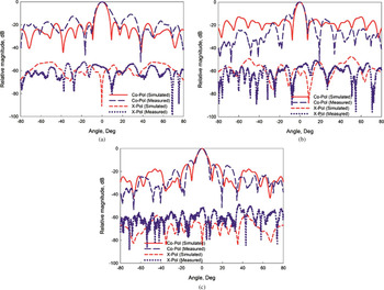
Now, the E-plane radiation patterns of the proposed reflectarray are estimated by both simulation and experiment. Subsequently they are plotted in Figs 7(a)–(c) for 10, 14, and 16.8 GHz, respectively. A good correlation is achieved between simulated and measured radiation patterns, and the measured 3-dB beam widths are observed to be 7.6, 6, and 5.4° at the frequencies of 10, 14, and 16.8 GHz, respectively. The side lobe level is well below −13 dB for the above frequencies, which is shown in Fig. 7. Further, the pattern symmetry in the E-plane is observed to be slightly deviated about the boresight radiation for 10 GHz, and is shown to be significantly better for the frequencies of 14 and 16.8 GHz, which are demonstrated in Fig. 7. Simulated and measured cross-polarization performances of the proposed reflectarray are plotted for the above frequencies in Fig. 7, which is found to be maximum of −50 dB in the entire observation angles.
Simulated and measured co- and cross-polarization radiation patterns in the E-plane at the frequencies of (a) 10 GHz, (b) 14 GHz, and (c) 16.8 GHz.

Gain and efficiency estimation
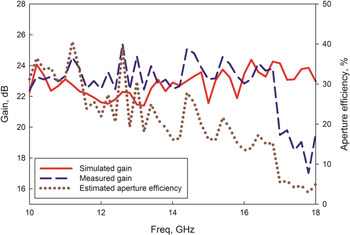
Simulated and measured gains of the proposed reflectarray are plotted as a function of frequency from 10 to 18 GHz in steps of 200 MHz in Fig. 8. It is observed that a discrepancy is noted between both gains at some frequencies such as, for example, 12.6, 13, and 14.4 GHz. This is deemed to be due to the correctness of simulation, where mesh and accuracy settings were provided based on the abovementioned computation facility, and also a semi anechoic measurement facility at the authors’ institution. A 3-dB gain bandwidth of 50.75% ranging from 10 to 16.8 GHz is achieved for the proposed reflectarray, which can be used to operate in both X/Ku and Ku frequency bands. Therefore, it is suitable to use the above reflectarray for direct broadcast satellite and remote sensing applications. Moreover, the aperture efficiency is estimated and plotted as a function of frequency in Fig. 8. The peak gain and aperture efficiency of the proposed reflectarray antenna are obtained at the frequency of 12.6 GHz, and found to be 25.4 dB and 40% respectively. This low efficiency observed at some frequencies is believed to be due to the small size of the reflectarray being employed to demonstrate the wideband operation of the proposed element [Reference Li, Bialkowski, Sayidmarie and Shuley18]. Beside this, the aperture efficiency is largely influenced by spillover and illumination or field tapering efficiencies, which in turn depend on feed horn characteristics and path loss variation between different elements locations [Reference Moharram and Kishk14]. While the optimum illumination taper is typically considered to be 10 dB [Reference Chaharmir, Shaker, Gagnon and Lee4, Reference Moharram and Kishk14], the feed horn used here offers 8 dB at the edge of reflectarray at the design frequency. Besides these, the frequency dependence of the multiple interactions between the feed and the reflectarray could also account for the variation of aperture efficiency with frequency [Reference Moharram and Kishk14].
Simulated and measured gains as a function of frequency.

Performance comparison
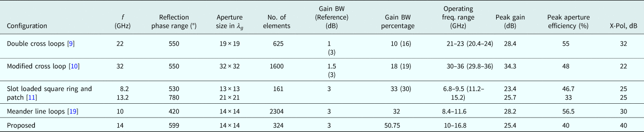
The configuration and characteristics of the proposed reflectarray are compared with those of the antenna structures reported in the open literature, which are shown in Table 2. It is inferred from Table 2 that the cross loop and square ring slots loaded patch element displays a dynamic reflection phase range of 599°, which is comparatively higher than the one obtained for the elements reported in [Reference Chaharmir, Shaker, Cuhaci and Ittipiboon9, Reference Wang, Shao, Li, Li and Cheng10, Reference Qin, Guo and Weily19], where the realized reflection phase is not more than 550°. The reflection phase of the proposed element does not significantly vary for an incident angle up to 35°, which makes it suitable for constructing large sized and offset-fed reflectarrays [Reference Shaker, Chaharmir and Ethier1]. Also, the element offers a linear phase response, which can be used for realizing a wideband reflectarray. Now, to make judicial comparison of the gain bandwidth performance of the proposed wideband reflectarray antenna with the existing structures reported in [Reference Chaharmir, Shaker, Cuhaci and Ittipiboon9, Reference Wang, Shao, Li, Li and Cheng10], the 3 dB gain bandwidth is estimated for them. The gain bandwidth comparison is presented in Table 2. It is good to see from Table 2 that the proposed reflectarray offers a very wide bandwidth of 50.75%. This translates to a 1.7:1 bandwidth ratio. This bandwidth ratio is significantly larger than that of the ones reported in [Reference Chaharmir, Shaker, Cuhaci and Ittipiboon9, Reference Wang, Shao, Li, Li and Cheng10, Reference Qin, Guo and Weily19]. And it exhibits a similar bandwidth performance as the design reported in [Reference Hamzavi-Zarghani and Atlasbaf11] in terms of operating frequency range. Further, in [Reference Hamzavi-Zarghani and Atlasbaf11], the reflectarray element is designed with an air dielectric of thickness 6 mm and dielectric substrate of thickness 0.813 mm, but the proposed one is constructed with a dielectric substrate thickness of 0.508 mm and an air dielectric thickness of 3 mm, thus reducing dielectric losses without compromising the bandwidth performance. The peak gain of the present reflectarray is well comparable with the one reported in [Reference Hamzavi-Zarghani and Atlasbaf11], but with the relatively small aperture size. However, the proposed antenna gain is less when compared to the reflectarrays realized in [Reference Chaharmir, Shaker, Cuhaci and Ittipiboon9, Reference Wang, Shao, Li, Li and Cheng10, Reference Qin, Guo and Weily19], which is essentially due to the smaller aperture size and much wider bandwidth than those antennas. Additionally, aperture efficiency is less when compared to reflectarray structures reported in [Reference Chaharmir, Shaker, Cuhaci and Ittipiboon9, Reference Hamzavi-Zarghani and Atlasbaf11, Reference Qin, Guo and Weily19]. This could be largely due to the wider gain bandwidth and small size of the reflectarray considered in this study, and other factors are discussed above. It is good to see that measured cross-polarization performance is better than that of the existing reflectarrays, as evidenced in Table 2. This proposed wideband reflectarray antenna exhibits a good bandwidth, gain, and cross-polarization performance with relatively simpler element configuration. Thus, it can be a good candidate to work in X/Ku and Ku frequency bands for satellite and remote sensing applications.
Performance of the proposed reflectarray antenna

Here guide wavelength,  $\lambda _g = \lambda _0/\sqrt {\varepsilon _{{\rm reff}}} $, λ 0, free space wavelength at the design frequency, and εreff ~ effective dielectric constant.
Conclusion
The cross loop and square ring slots loaded patch elements based wide band reflectarray was presented in this paper. Initially the unit cell element was analyzed for its reflection phase by employing infinite array approach. It has offered a wide and linear dynamic reflection phase response when compared to the appropriate elements reported in open literature. The elements were used to construct 200 × 200 mm2 reflectarray according to the compensation phase. Subsequently, a reflectarray antenna prototype was analyzed and optimized for its radiation performances by both simulation and measurement. It was noted that the proposed reflectarray displayed a very wide 3-dB gain bandwidth of 50.75% with an operating frequency range of 10–16.8 GHz i.e. a 1.7:1 bandwidth ratio. And it has exhibited a maximum gain of 25.4 dB and a peak aperture efficiency of 40%. Therefore, this reflectarray antenna can be used to operate in X/Ku and Ku bands for remote sensing and satellite applications.
Author ORCIDs
M. Gulam Nabi Alsath, 0000-0003-0534-9650
Acknowledgement
This work was supported by the Indian Space Research Organization Sponsored Research programme (ISRO-RESPOND). The authors would like to thank Associate Editor and Reviewers for their useful comments and suggestions to improve this article.