1. Introduction
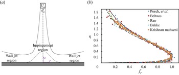
Radial wall jets play an essential role in many scientific and engineering endeavours, from modern electronics and medicine to mining and nuclear waste processing. For example, radial wall jets launch vertical-take-off aircraft, govern the flow of sprays in diesel engines, suspend and mobilize solids from settled beds and remove particles in computer chip manufacturing (Glauert Reference Glauert1956; Phares, Smedley & Flagan Reference Phares, Smedley and Flagan2000; Pease, Bamberger & Minette Reference Pease, Bamberger and Minette2015). Radial wall jets form as circular jets (fully developed or developing from potential cores) impinge on surfaces (Glauert Reference Glauert1956; Bakke Reference Bakke1957; Bradshaw & Love Reference Bradshaw and Love1961; Tsuei Reference Tsuei1962; Heskestad Reference Heskestad1966; Poreh, Tsuei & Cermak Reference Poreh, Tsuei and Cermak1967; Beltaos & Rajaratnam Reference Beltaos and Rajaratnam1974; Beltaos Reference Beltaos1976; Rajaratnam Reference Rajaratnam1976; Özdemir & Whitelaw Reference Özdemir and Whitelaw1992; Loureiro & Silva Freire Reference Loureiro and Silva Freire2012; Banyassady Reference Banyassady2015; Wu, Banyassady & Piomelli Reference Wu, Banyassady and Piomelli2016; van Hout, Rinsky & Grobman Reference van Hout, Rinsky and Grobman2018; Rönnberg & Duwig Reference Rönnberg and Duwig2021). At the point of impingement, Beltaos (Reference Beltaos1976) and Bradshaw & Love (Reference Bradshaw and Love1961) show that the local pressure develops an approximately Gaussian distribution at the wall, with the peak pressure at the point of impingement (see figure 1a). The elevated pressure at this point drives a transverse velocity, which directs flow radially outward. This flow may be initially laminar with a peak velocity near the wall and approximately Gaussian decay from the wall (Kobus, Leister & Westrich Reference Kobus, Leister and Westrich1979). As this velocity profile progresses radially, a no-slip boundary condition leads to the development of a distinctive velocity profile (figure 1b) that rises sharply near the wall and then more gradually attenuates away from the wall. When the inertial forces of the jet exceed the viscous forces of the fluid, this boundary layer generates vortices such that the radial wall jet becomes turbulent a short distance from the point of impingement (Phares et al. Reference Phares, Smedley and Flagan2000). The dynamics of this impingement region has been studied in some detail, including the influence of surface roughness (Abramovich Reference Abramovich1963; Kobus et al. Reference Kobus, Leister and Westrich1979; Rajaratnam & Mazurek Reference Rajaratnam and Mazurek2005; Wu et al. Reference Wu, Banyassady and Piomelli2016; van Hout et al. Reference van Hout, Rinsky and Grobman2018; Rönnberg & Duwig Reference Rönnberg and Duwig2021). However, the friction developed by the fully turbulent radial wall jet outside of the entrance region where the pressure gradient has vanished is the focus of this article.
(a) Essential features of the radial wall jet formed by normal impingement of a circular jet including the impingement region with Gaussian pressure profile (short dash) and the wall jet region (the focus of this article) highlighted. The nozzle velocity and diameter are Uo and do, respectively. (b) The velocity profile in the wall region with elevation scaled on the outer jet thickness, η, versus the local velocity scaled on the peak velocity, fr, from figures 2, 4 and 7 of Poreh et al. (Reference Poreh, Tsuei and Cermak1967); figure 14 of Beltaos (Reference Beltaos1976); figure 3 of Rao (Reference Rao1980); figure 8 of Krishnan & Mohseni (Reference Krishnan and Mohseni2010); and figure 11-2 of Rajaratnam (Reference Rajaratnam1976). The solid black curve corresponds to Verhoff's (Reference Verhoff1963) theoretical approximation (2.43), and the dashed black curve corresponds to the empirical Weibull distribution reported by Loureiro & Silva Freire (their (2.7)) (Reference Loureiro and Silva Freire2012). The peak velocity occurs at η = 0.237 ± 0.064.

Despite decades of investigation, general agreement on the expression for the friction coefficient for turbulent radial wall jets outside of the impingement region remains elusive. This is due in part to the selection of power-law expressions to represent friction factor expressions based on the pioneering work of Prandtl, von Kármán and Glauert (Colebrook Reference Colebrook1939; Glauert Reference Glauert1956). Although engineering expressions for friction factors for pipe flow quickly migrated to logarithmic expressions based on the ‘law of the wall’, skin coefficients of friction for radial wall jets persist in using power-law expressions (Colebrook Reference Colebrook1939). For example, Poreh et al. (Reference Poreh, Tsuei and Cermak1967) express the skin coefficient of friction as  ${c_f} = 0.06{({u_m}{\delta _m}/\nu )^{ - 0.3}}{(r/H)^{ - 0.16}}$, where um is the maximum velocity, δm is a characteristic length scale, ν is the kinematic viscosity, r is the radius and H is the standoff distance between the nozzle and the impinged upon surface. Bradshaw & Gee (Reference Bradshaw and Gee1962) give the skin coefficient of friction as
 ${c_f}\sim {({u_m}{\delta _m}/\nu )^{ - 0.182}}$. Alternatively, Beltaos (Reference Beltaos1976) first reports both
 ${c_f} = 0.328Re_o^{ - 0.3}$ for 72 000 ≤ Reo ≤ 325 000, where Reo is the nozzle Reynolds number (their (24)) and cf = 0.0126 for 31 800 ≤ Reo ≤ 55 300 (their (25)) before summarizing
 ${c_f} = 0.098Re_o^{ - 1/5}$ (their (26)). Rajaratnam (Reference Rajaratnam1976) proposes
 ${c_f} = 0.238Re_o^{ - 0.54}$ (see his figure 11–17) based on the work of Tsuei (Reference Tsuei1962). Similarly, Dawson & Trass (Reference Dawson and Trass1966) suggest the skin coefficient is proportional to
 ${({u_m}{\delta _m}/\nu )^{ - 0.25}}$ or
 $Re_o^{ - 0.20}$. The range of power-law exponents and coefficients is striking, suggesting that additional factors not previously considered play a vital role, and none of these expressions accounts for surface roughness often characteristic of practical or engineered surfaces.
Glauert's seminal article on radial wall jets suggests that one reason for the discrepancy may arise from approximating the velocity profile near the wall using Blasius’ one-seventh power-law approximation (Blasius Reference Blasius1912; Glauert Reference Glauert1956). Glauert acknowledges that ‘This power-law expression is easier to apply … than is the logarithmic relation which is theoretically more acceptable’ (p. 634). Yet, the logarithmic law with accommodations for surface roughness has yet to be applied to radial wall jets. Indeed, Loureiro & Silva Freire (Reference Loureiro and Silva Freire2012) summarize the sparse analysis of radial wall jets across nominally smooth surfaces to find sets of law of the wall parameters to be surprisingly heterogeneous. These expressions were not converted into expressions for skin coefficients of friction, leaving the best expression for smooth surfaces unclear and the role of surface roughness completely unexplored. Building on Glauert's power-law analysis, Verhoff combined a complementary error function with a one-seventh power law to provide a single and simple expression for the velocity profile of wall jets (Verhoff Reference Verhoff1963). However Rajaratnam (Reference Rajaratnam1967) finds that the one-seventh power law does not strictly hold in the development of planar wall jets (formed by wide slot or circular nozzles instead of circular jet impingement), similar to Clauser's assertion of power-law exponents that range over 1/10–1/3 and Barenblatt & Goldenfeld's assertion of a power-law exponent of 3/(2ln(Re)), both for pipe flow (Clauser Reference Clauser1956; Barenblatt & Goldenfeld Reference Barenblatt and Goldenfeld1995). This is important because industrial scale vessels where radial jets drive mixing are not ideally smooth but constructed of practical materials with a finite roughness and may roughen over time with use. The ‘gold standard’ for friction factor analyses for pipe flow has been the Colebrook equation (Colebrook Reference Colebrook1939). This equation was developed to asymptotically and smoothly approximate the pipe friction factor for both smooth and rough surfaces. Recent developments by Afzal et al., provide simple, continuous and accurate expressions for turbulent flow over smooth, rough and transitional surfaces benchmarked against both Nikuradse's classical data and Princeton superpipe experiments, suggesting a compelling opportunity to revisit and complete this classic jet physics problem (Nikuradse Reference Nikuradse1933; Zagarola, Perry & Smits Reference Zagarola, Perry and Smits1997; Afzal, Seena & Bushra Reference Afzal, Seena and Bushra2013).
In the remainder of this article, we first derive the velocity profiles for fully turbulent radial wall jet equations from conservation of momentum and mass for single-phase jets. We then combine the inner and outer portion of the velocity profile from which expressions for the skin coefficient of friction arise naturally. The fully iterative solution (2.35), based on the well-established asymptotic concepts of turbulent wall-bounded flow in agreement with Afzal et al. (Reference Afzal, Seena and Bushra2013) and in line with Colebrook (Reference Colebrook1939), is presented along with a power-law approximation and a non-iterative approximation for the friction coefficient (Serghides Reference Serghides1984).
2. Materials and methods
This derivation has three parts. First, we derive the near-wall velocity profile comparing the logarithmic portion with the velocity expressions of Colebrook (Reference Colebrook1939) and Afzal et al. (Reference Afzal, Seena and Bushra2013) and briefly review the derivation of the outer portion of the velocity profile. Second, we determine the skin coefficients of friction for radial wall jets. Third, we generate power-law and non-iterative approximations of the skin coefficients of friction from the logarithmic expression and explore the implications thereof for velocity profiles over smooth and nearly smooth surfaces as a means of comparing with the prior work of others.
2.1. The inner velocity profile
Conservation of momentum after Reynolds averaging leads to
 \begin{equation}\rho \left( {\frac{{\partial \boldsymbol{v}}}{{\partial t}} + \boldsymbol{v}\,\boldsymbol{\cdot }\,\boldsymbol{\nabla }\boldsymbol{v}} \right) ={-} \boldsymbol{\nabla }\wp + \boldsymbol{\nabla }\,\boldsymbol{\cdot }\,(\boldsymbol{\tau } + {\boldsymbol{\tau }^t}),\end{equation}
where ρ is the fluid density, v is the velocity vector, t is time,  $\wp $ is the dynamic pressure, τ is the deviatoric stress tensor and
 ${\boldsymbol{\tau }^t}$ is the turbulent Reynolds stress tensor (not a transpose). For steady-state axisymmetric flow in cylindrical coordinates (r, z, θ), the two components are
 \begin{equation}\rho \left( {{v_r}\frac{{\partial {v_r}}}{{\partial r}} + {v_z}\frac{{\partial {v_r}}}{{\partial z}}} \right) ={-} \frac{{\partial \wp }}{{\partial r}} + \frac{\partial }{{\partial z}}({\tau _{zr}} + \tau _{zr}^t) + \frac{1}{r}\frac{\partial }{{\partial r}}[r({\tau _{rr}} + \tau _{rr}^t)]\end{equation}
and
 \begin{equation}\rho \left( {{v_r}\frac{{\partial {v_z}}}{{\partial r}} + {v_z}\frac{{\partial {v_z}}}{{\partial z}}} \right) ={-} \frac{{\partial \wp }}{{\partial z}} + \frac{\partial }{{\partial z}}({\tau _{zz}} + \tau _{zz}^t) + \frac{1}{r}\frac{\partial }{{\partial r}}[r({\tau _{rz}} + \tau _{rz}^t)],\end{equation}
where vr and vz are the r and z components of the velocity, respectively. We may scale r on do, z on βrdo, vr on Uo, vz on βrUo,  $\wp $ on
 $\mu {U_o}/(\beta _r^2{d_o})$, τzr and τrz on
 $\mu {U_o}/(\beta _r{d_o})$ and τrr and τzz on
 $\mu {U_o}/{d_o}$, where do is the nozzle diameter, Uo is the nozzle velocity, βr is the radial jet spread or arctangent of the angle that the radial wall jet makes with respect to the wall and μ is the dynamic viscosity. Scaling then returns
 \begin{equation}\beta _r^2R{e_o}\left( {{{\bar{v}}_r}\frac{{\partial {{\bar{v}}_r}}}{{\partial \bar{r}}} + {{\bar{v}}_z}\frac{{\partial {{\bar{v}}_r}}}{{\partial \bar{z}}}} \right) ={-} \frac{{\partial \bar{\wp }}}{{\partial \bar{r}}} + \frac{\partial }{{\partial \bar{z}}}({\bar{\tau }_{zr}} + \bar{\tau }_{zr}^t) + {\beta _r}^2\frac{1}{{\bar{r}}}\frac{\partial }{{\partial \bar{r}}}[\bar{r}({\bar{\tau }_{rr}} + \bar{\tau }_{rr}^t)],\end{equation}
and
 \begin{equation}\beta _r^4R{e_o}\left( {{{\bar{v}}_r}\frac{{\partial {{\bar{v}}_z}}}{{\partial \bar{r}}} + {{\bar{v}}_z}\frac{{\partial {{\bar{v}}_z}}}{{\partial \bar{z}}}} \right) ={-} \frac{{\partial \bar{\wp }}}{{\partial \bar{z}}} + {\beta _r}^2\frac{\partial }{{\partial \bar{z}}}({\bar{\tau }_{zz}} + \bar{\tau }_{zz}^t) + {\beta _r}^2\frac{1}{{\bar{r}}}\frac{\partial }{{\partial \bar{r}}}[\bar{r}({\bar{\tau }_{rz}} + \bar{\tau }_{rz}^t)],\end{equation}
where Reo = ρdoUo/μ and overbars indicate scaled quantities. Removing  $\beta _r^2$ terms
 $(\beta _r^2 \ll 1)$ but preserving
 $\beta _r^2R{e_o}$ terms leaves
 \begin{equation}\beta _r^2R{e_o}\left( {{{\bar{v}}_r}\frac{{\partial {{\bar{v}}_r}}}{{\partial \bar{r}}} + {{\bar{v}}_z}\frac{{\partial {{\bar{v}}_r}}}{{\partial \bar{z}}}} \right) ={-} \frac{{\partial \bar{\wp }}}{{\partial \bar{r}}} + \frac{\partial }{{\partial \bar{z}}}({\bar{\tau }_{zr}} + \bar{\tau }_{zr}^t),\end{equation}
and
 \begin{equation}0 ={-} \frac{{\partial \bar{\wp }}}{{\partial \bar{z}}}.\end{equation}
Therefore, the pressure is very nearly constant vertically, after a Gaussian entrance region (Beltaos Reference Beltaos1976), and the radial component of momentum includes viscous terms that persist. In the next section, integration of (2.4a) over z from the wall would find the radial pressure gradient multiplied by infinity unless the dynamic pressure is set to zero consistent with both Gaussian decay and the traditional argument of isobaric wall jets (Beltaos Reference Beltaos1976; Rajaratnam Reference Rajaratnam1976). Then without scaling,
 \begin{equation}\rho {v_r}\frac{{\partial {v_r}}}{{\partial r}} + \rho {v_z}\frac{{\partial {v_r}}}{{\partial z}} = \frac{\partial }{{\partial z}}({\tau _{zr}} + \tau _{zr}^t).\end{equation}
This is the starting point for the outer jet analysis. To determine the terms that persist near the wall, we rescale the velocities on the wall friction velocity, uw, with  $({v_r},{v_z}) = ({u_w}v_r^ + ,{u_w}{\beta_r}v_z^ + )$, lengths on the boundary layer thickness δν, with
 $(r,z) = ({\delta _\nu }{r^ + },{\delta _\nu }{\beta _r}{z^ + })$, and shear stresses as
 $({\tau _{rz}},\tau _{rz}^t) = (\mu {u_w}/({\beta _r}{\delta _\nu }))(\tau _{rz}^ + ,\tau _{rz}^{t + })$, so that
 \begin{equation}\beta _r^2R{e_\nu }\left( {{v_r}^ + \frac{{\partial v_r^ + }}{{\partial {r^ + }}} + v_z^ + \frac{{\partial v_r^ + }}{{\partial {z^ + }}}} \right) = \frac{\partial }{{\partial {z^ + }}}(\tau _{zr}^ +{+} \tau _{zr}^{t + }),\end{equation}
where Reν = δνuw/ν, ν is the kinematic viscosity and δν = ν/uw so that Reν = 1. The magnitude of the term on the left is then small  $(\beta _r^2 \ll 1)$, leaving
 \begin{equation}\frac{\textrm{d}}{{\textrm{d}z}}({\tau _{zr}} + \tau _{zr}^t) = 0,\end{equation}
with scaling removed as the starting point for the inner analysis.
Integrating over z yields
 \begin{equation}{\tau _{zr}} + \tau _{zr}^t = {\tau _w},\end{equation}
where the needed constant of integration is defined as τw, the shear stress at the wall. Although τw is practically constant as a function of z near the wall, this integration step does not prohibit τw from varying radially. Selecting τw for the integration constant is justified for a smooth wall (z = 0), because the Reynolds stress vanishes due to viscous damping so that the wall stress is identified precisely with the viscous stress in traditional form (Reichardt Reference Reichardt1951; van Driest Reference van Driest1956). The implication here is compelling because this is precisely the same expression as is obtained for pipe flow in the vicinity of the pipe wall (where the wake correction remains negligible), establishing an immediate synergy between the two geometries as anticipated by the universality of the ‘law of the wall’. Implementing the Newtonian constitutive equation for the shear stress and Prandtl's mixing length hypothesis yields
 \begin{equation}{\tau _w} = \mu \frac{{\textrm{d}{v_r}}}{{\textrm{d}z}} + \rho {l^2}\left|{\frac{{\textrm{d}{v_r}}}{{\textrm{d}z}}} \right|\frac{{\textrm{d}{v_r}}}{{\textrm{d}z}},\end{equation}
where l is Prandtl's mixing length. As described by van Driest (Reference van Driest1956), Prandtl's mixing length in the vicinity of a rough surface may be expressed as
 \begin{equation}l = \kappa z\left[ {1 - \textrm{exp}\left( { - \frac{z}{{26{\delta_\nu }}}} \right) + \textrm{exp}\left( { - \frac{{60z}}{{26k}}} \right)} \right],\end{equation}
with κ as von Kármán's universal constant
 \begin{equation}\kappa = \frac{1}{{4\sqrt 2 {{\log }_{10}}{\rm e}}} \approx 0.407,\end{equation}
as given by Colebrook's derivation (Reference Colebrook1939) though many subsequent authors have treated it as an empirical variable to be determined experimentally, k is the dimensional roughness, and the wall friction velocity is defined as  ${u_w} = {({\tau _w}/\rho )^{1/2}}$. Alternative expressions for the mixing length are available (Grifoll & Giralt, Reference Grifoll and Giralt2000). Algebraically isolating the velocity gradient (positive definite in the vicinity of the wall) with substitution returns
 \begin{equation}\frac{{{v_r}}}{{{u_w}}} = \int_0^z {\frac{{ - {\delta _\nu } + \sqrt {{\delta _\nu }^2 + 4{l^2}} }}{{2{l^2}}}\,\textrm{d}z} ,\end{equation}
or in terms of wall variables ( $v_r^ += {v_r}/{u_w},{z^ + } = z/{\beta _r}{\delta _\nu }$, and
 ${k^ + } = k/{\beta _r}{\delta _\nu }$)
 \begin{equation}v_r^ +{=} \int_0^{{z^ + }} {\frac{{ - 1 + \sqrt {1 + 4\beta _r^2{\kappa ^2}{z^{ + 2}}{{\left[ {1 - \textrm{exp}\left( { - {\beta_r}\frac{{{z^ + }}}{{26}}} \right) + \textrm{exp}\left( { - \frac{{60{z^ + }}}{{26{k^ + }}}} \right)} \right]}^2}} }}{{2{\beta _r}{\kappa ^2}{z^{ + 2}}{{\left[ {1 - \textrm{exp}\left( { - {\beta_r}\frac{{{z^ + }}}{{26}}} \right) + \textrm{exp}\left( { - \frac{{60{z^ + }}}{{26{k^ + }}}} \right)} \right]}^2}}}\,\textrm{d}{z^ + }} .\end{equation}
See Scheichl & Kluwick (Reference Scheichl and Kluwick2013) for an alternative approach to the law of the wall. This equation provides the near-wall velocity profile for both smooth and rough surfaces. The limit as z + becomes large but not larger than the peak in figure 2 (where  $l \gg {\delta _\nu }$ so that the argument of square root above becomes a perfect square) is insightful. Here
 \begin{equation}\frac{{{v_r}}}{{{u_w}}} = \frac{1}{\kappa }\int_{{z_1}}^z {\frac{{\textrm{d}z}}{z}} = \frac{1}{\kappa }\ln \frac{z}{{{z_1}}},\end{equation}
where the constant z1 (essentially a slip length) must account for both the viscous damping and the influence of roughness. (A no-slip boundary condition strictly holds at the surface, but because the log law does not include the viscous sublayer a slip layer-like approximation becomes necessary.) For rough and roughened surfaces Colebrook (Reference Colebrook1939) asserts
 \begin{equation}{z_1} = \frac{k}{{33}} + \frac{1}{{10}}{\delta _\nu },\end{equation}
based on the impressively precise experimental work of Nikuradse (Reference Nikuradse1933). Afzal et al. expand the expression to represent the transition region between smooth and rough pipes for turbulent flow as
 \begin{equation}{z_1} = \alpha {\delta _v} + \beta k(1 - {\textrm{e}^{ - k/26{\delta _v}}}),\end{equation}
with a van Driest-type expression with α = e−κB = 0.107 and  $\beta = {\textrm{e}^{ - \kappa {B_T}}} = 0.0314$ from B = 5.5 and BT = 8.5, which close to the values of 1/10 and 1/33 given by Colebrook (Colebrook Reference Colebrook1939; Afzal et al. Reference Afzal, Seena and Bushra2013). Substitution yields
 \begin{equation}{v_r} ={-} \frac{{{u_w}}}{\kappa }\ln \left[ {\alpha \frac{{{\delta_v}}}{z} + \frac{{\beta k}}{z}(1 - {\textrm{e}^{ - k/26{\delta_v}}})} \right],\end{equation}
or in wall variables,
 \begin{equation}v_r^ +{=} - \frac{1}{\kappa }\ln \left[ {\frac{\alpha }{{{\beta_r}{z^ + }}} + \frac{{\beta {k^ + }}}{{{z^ + }}}(1 - {\textrm{e}^{ - {\beta_r}{k^ + }/26}})} \right],\end{equation}
which may be compared with the velocity profiles of (2.13) (compare lines in figure 2 from (2.17) with curves from (2.13) that overlap in the large z+ limit). Comparing data with the curves suggests that the relative roughness, k +, decreases further away from the jet axis, the cause of which was not discussed by Poreh et al. (Reference Poreh, Tsuei and Cermak1967) but is commensurate with the analysis below.
Velocity divided by wall friction velocity, u/uw, versus elevation divided by boundary layer thickness, z +, for k + = 0.01 (blue long dash), 3 (red short dash), 15 (green dotted) and 60 (brown alternating dash) using both numerical integration of (2.13) (thick curves) and the logarithmic approximation of (2.17) (linear on the log linear plot). Experimental data from figure 10 of Poreh et al. (Reference Poreh, Tsuei and Cermak1967) for r = 18 (diamonds), 30 (triangles), 42 (squares) and 66 inches (circles).

2.2. The outer velocity profile
We now multiply (2.5) by r and integrate over z without the scaling
 \begin{equation}\int_0^\infty {\rho {v_r}r\frac{{\partial {v_r}}}{{\partial r}}\,\textrm{d}z} + \int_0^\infty {\rho {v_z}r\frac{{\partial {v_r}}}{{\partial z}}\,\textrm{d}z} = \int_0^\infty {r\frac{\partial }{{\partial z}}({\tau _{zr}} + \tau _{zr}^t)\,\textrm{d}z} .\end{equation}
Integration by parts with the help of continuity,
 \begin{equation}\frac{{\partial r{v_r}}}{{\partial r}} + \frac{{\partial r{v_z}}}{{\partial z}} = 0,\end{equation}
returns
 \begin{equation}\frac{\textrm{d}}{{\textrm{d}r}}\int_0^\infty {r\rho v_r^2\,\textrm{d}z} + r\rho {v_z}{v_r}|_0^\infty = r({\tau _{zr}} + \tau _{zr}^t)|_0^\infty .\end{equation}
The second term on the left vanishes because vz vanishes at the surface due to a no-slip boundary condition and attenuates far from the surface. The shear stress from the jet must vanish far from the wall, and the shear stress near the wall must become the wall shear stress leaving only
 \begin{equation}\frac{\textrm{d}}{{\textrm{d}r}}\int_0^\infty {\rho rv_r^2\,\textrm{d}z} ={-} r{\tau _w},\end{equation}
or with constant density,
 \begin{equation}\frac{\textrm{d}}{{\textrm{d}r}}\int_0^\infty {rv_r^2\,\textrm{d}z} ={-} ru_w^2,\end{equation}
because  ${u_w} = {({\tau _w}/\rho )^{1/2}}$ is the wall friction velocity or wall shear velocity. This equation shows that momentum is preserved except as lost to the wall. Complete solution requires either an expression for vr or τw. The solution below selects the latter and determines an expression for the skin coefficient of friction.
A limiting case may be insightful. Consider a radial jet in quiescent media (entering momentum only from a primary circular jet) so that (2.21a) may be integrated as
 \begin{equation}2{\rm \pi}\int_0^\infty {\rho rv_r^2\,\textrm{d}z} = \frac{\rm \pi}{4}\rho U_o^2d_o^2{\psi _p} - 2{\rm \pi}\int_{{d_o}/2}^r {{\tau _w}r\,\textrm{d}r} ,\end{equation}
where the first term on the right represents the momentum from the single circular jet and the factor
 \begin{equation}{\psi _p} = \frac{8}{{U_o^2d_o^2}}\int_0^{{d_o}/2} {v_p^2r\,\textrm{d}r} ,\end{equation}
accounts for radial variations in the velocity profile emerging from the nozzle with vp representing the axial velocity of the primary jet as a function of radius within the nozzle. For ideal plug flow, ψp = 1. Equation (2.22) may be simplified by asserting similarity with vr = vm,r(r)fr(ηr), where the local peak velocity at any radial position, vm,r, may be expressed as
 \begin{equation}{v_{m,r}} = \frac{{{h_r}{U_o}{d_o}}}{r},\end{equation}
with hr as the velocity decay coefficient, and ηr = z/δr assuming the virtual origin of the radial wall jet to be approximately negligible (see figures 11–14 of Rajaratnam), where δr = βrr is the characteristic thickness of the jet in the absence of a virtual origin correction. A skin coefficient of friction may be defined in the Fanning form as
 \begin{equation}{\tau _w} = {\textstyle{1 \over 2}}{c_f}\rho v_{m,r}^2\end{equation}
(a Darcy form would have a leading coefficient of 1/8). Asserting the skin coefficient of friction to be strictly constant (true for smooth surfaces as argued below) and the velocity decay coefficient to be independent of radius to first order (an assertion to be tested momentarily) returns the velocity decay coefficient
 \begin{equation}{h_r} = \sqrt {\frac{{{\psi _p}}}{{8{\beta _r}\int_0^\infty {f_r^2\,\textrm{d}\eta } + 4{c_f}\ln \frac{{2r}}{{{d_o}}}}}} ,\end{equation}
showing this coefficient to be marginally smaller with friction. However, for many (but not all) cases, the correction associated with friction is usually second order (<1 %, see figure 3b) such that the correction remains smaller than experimental uncertainty in velocity measurement (Poreh et al. Reference Poreh, Tsuei and Cermak1967; Rajaratnam Reference Rajaratnam1976). Neglecting the second term in the denominator, the jet spread may be estimated from
 \begin{equation}{\beta _r} = \frac{{{\psi _p}}}{{8h_r^2\int_0^\infty {f_r^2\,\textrm{d}\eta } }},\end{equation}
when hr is known from experiment. The dependence of the jet spread on angle of impingement may then be estimated from (2.38) of Beltaos, who considered the non-normal impingement of a jet on a flat plate to find
 \begin{equation}{h_r} = 1.1\frac{{1 + \cos \phi }}{{\sqrt {\sin \phi } }},\end{equation}
where ϕ is the acute angle between the centreline of the jet and the impinged upon plate (Beltaos Reference Beltaos1976). Substitution returns
 \begin{equation}{\beta _r} = \frac{{{\psi _p}\sin \phi }}{{9.68{{(1 + \cos \phi )}^2}\int_0^\infty {f_r^2\,\textrm{d}\eta } }}.\end{equation}
These two equations are used to reduce the information in table 3 of Beltaos for figure 3(a).
(a) Skin coefficient of friction, cf, for rough surfaces versus the βrhrReo product for k/δr = 0 (bottom solid blue, smooth), 0.0001 (long dashed red), 0.001 (short dash green), 0.01 (dotted brown), 0.1 (short alternating dash purple), 0.3 (long alternating gold) and 1.0 (top alternating double dash bright green) from (2.35). Data (blue circles) from table 3 of Beltaos (Reference Beltaos1976) with βr and hr from (2.28) and (2.29) with ψp = 1 and (red squares) figure 8 of Poreh et al. (Reference Poreh, Tsuei and Cermak1967) with hr = 1.1, βr = 0.087 evaluated at r = H. Poreh et al. indicate a 15 % uncertainty in shear stress measurement. (b) Relative uncertainty from the Serghides-like approximation ((2.36) and (2.37)) at the same conditions (Serghides Reference Serghides1984).

2.3. The friction coefficient
The friction coefficient may now be determined to complete the solution through provision of a boundary layer thickness. As mentioned previously, the inner velocity solution is remarkably similar to that derived for pipe flow by Colebrook (Reference Colebrook1939). However, here we diverge from Colebrook in two meaningful ways. First, we define the skin coefficient of friction, cf, following the work of Beltaos (Reference Beltaos1976) as given in (2.25). Second, whereas Colebrook was able to determine a location in the pipe where the local velocity equalled the mean velocity by integrating the well-developed equivalent of (2.5), we must determine a point in the velocity profile by other means. Here we recognize the extensive data sets accumulated by others over several prior decades. Reanalysis of their data in figure 1(b) gives vr = vm,r at ηmax = z/δr = 0.237 ± 0.064. Averages and standard deviations are only calculated for points where vr/vm,r ≥ 0.98. Substitution of this relationship into (2.17) yields
 \begin{equation}{v_{m,r}} ={-} \frac{{{u_w}}}{\kappa }\ln \left[ {\frac{1}{{{\eta_{max}}{\delta_r}}}(\alpha {\delta_\nu } + \beta k(1 - {\textrm{e}^{ - k/26{\delta_\nu }}}))} \right].\end{equation}
Algebraic rearrangement with (2.11) then leaves
 \begin{equation}\frac{1}{{\sqrt {{c_f}} }} ={-} 4{\log _{10}}\left[ {\frac{{{{\alpha \sqrt 2 } / {{\eta_{max}}}}}}{{Re\sqrt {{c_f}} }} + \frac{{k/{\delta_r}}}{{{\eta_{max}}/\beta }}\left( {1 - \textrm{exp}\left[ { - \frac{{kRe\sqrt {{c_f}} }}{{26\sqrt 2 {\delta_r}}}} \right]} \right)} \right],\end{equation}
where
 \begin{equation}Re = \frac{{\rho {\delta _r}{v_{m,r}}}}{\mu }.\end{equation}
This has a similar form to the traditional Colebrook equation. However, all useful experimental data correlate back to the nozzle Reynolds number instead of the local Reynolds number so that
 \begin{equation}Re = {\beta _r}{h_r}\frac{{\rho {U_o}{d_o}}}{\mu } = {\beta _r}{h_r}R{e_o},\end{equation}
in the absence of a virtual origin correction, from which
 \begin{equation}\frac{1}{{\sqrt {{c_f}} }} ={-} 4{\log _{10}}\left[ {\frac{{{{\alpha \sqrt 2 } / {{\eta_{max}}}}}}{{{\beta_r}{h_r}R{e_o}\sqrt {{c_f}} }} + \frac{{k/{\delta_r}}}{{{\eta_{max}}/\beta }}\left( {1 - \textrm{exp}\left[ { - \frac{{k{\beta_r}{h_r}R{e_o}\sqrt {{c_f}} }}{{26\sqrt 2 {\delta_r}}}} \right]} \right)} \right].\end{equation}
Substituting values indicated (from below (2.16) α = 0.107, β = 0.0314, ηmax = 0.237) returns
 \begin{equation}\frac{1}{{\sqrt {{c_f}} }} ={-} 4{\log _{10}}\left[ {\frac{{0.638}}{{{\beta_r}{h_r}R{e_o}\sqrt {{c_f}} }} + \frac{k}{{7.55{\delta_r}}}\left( {1 - \textrm{exp}\left[ { - \frac{{k{\beta_r}{h_r}R{e_o}\sqrt {{c_f}} }}{{36.8{\delta_r}}}} \right]} \right)} \right].\end{equation}
This is the essential result given herein.
2.4. Non-iterative Serghides-like approximation
Because the original Colebrook equation and the expression evaluated herein are transcendental, convenient expressions to facilitate calculations remain desirable. Here, we select the approach developed by Serghides because it is readily implemented without the need for iteration (Henrici Reference Henrici1964; Serghides Reference Serghides1984). Yet, (2.35) is also of the form x = f(x) permitting a non-iterative approximation as
 \begin{equation}{c_f} = {\left( {A - \frac{{{{(B - A)}^2}}}{{C - 2B + A}}} \right)^{ - 2}},\end{equation}
with
 \begin{gather}A ={-} 4{\log _{10}}\left[ {\frac{{0.638}}{{{\beta_r}{h_r}R{e_o}}} + \frac{k}{{7.55{\delta_r}}}\left( {1 - \textrm{exp}\left[ { - \frac{{k{\beta_r}{h_r}R{e_o}}}{{36.8{\delta_r}}}} \right]} \right)} \right],\end{gather}
 \begin{gather}B ={-} 4{\log _{10}}\left[ {\frac{{0.638A}}{{{\beta_r}{h_r}R{e_o}}} + \frac{k}{{7.55{\delta_r}}}\left( {1 - \textrm{exp}\left[ { - \frac{{k{\beta_r}{h_r}R{e_o}}}{{36.8{\delta_r}A}}} \right]} \right)} \right],\end{gather}
and
 \begin{equation}C ={-} 4{\log _{10}}\left[ {\frac{{0.638B}}{{{\beta_r}{h_r}R{e_o}}} + \frac{k}{{7.55{\delta_r}}}\left( {1 - \textrm{exp}\left[ { - \frac{{k{\beta_r}{h_r}R{e_o}}}{{36.8{\delta_r}B}}} \right]} \right)} \right].\end{equation}
In the absence of the exponential in (2.35) and (2.37), other simplifications may be available (Corless et al. Reference Corless, Gonnet, Hare, Jeffrey and Knuth1996; Clamond Reference Clamond2009; Schlichting & Gersten Reference Schlichting and Gersten2016).
2.5. Power-law approximation
As described in the introduction, much of the skin coefficient of friction data have been plotted as a function of the nozzle Reynolds number in the form of
 \begin{equation}{c_f} = mRe_o^n.\end{equation}
Reformulating the results of (2.35) into the form of (2.38) provides an additional means of validating (2.35). Taking the logarithm and derivative gives
 \begin{equation}n = \frac{{\textrm{d}\ln {c_f}}}{{\textrm{d}\ln R{e_o}}},\end{equation}
where m is taken as a constant independent of Reo. Implicit differentiation gives
 \begin{equation}n = \frac{{2\left( {\frac{{0.638}}{{{\beta_r}{h_r}R{e_o}\sqrt {{c_f}} }} - \frac{{{\beta_r}{h_r}R{e_o}\sqrt {{c_f}} }}{{278}}\frac{{{k^2}}}{{\delta_r^2}}\textrm{exp}\left[ { - \frac{k}{{{\delta_r}}}\frac{{{\beta_r}{h_r}R{e_o}\sqrt {{c_f}} }}{{36.8}}} \right]} \right)}}{{x\ln x - \left( {\frac{{0.638}}{{{\beta_r}{h_r}R{e_o}\sqrt {{c_f}} }} - \frac{{{\beta_r}{h_r}R{e_o}\sqrt {{c_f}} }}{{278}}\frac{{{k^2}}}{{\delta_r^2}}\textrm{exp}\left[ { - \frac{k}{{{\delta_r}}}\frac{{{\beta_r}{h_r}R{e_o}\sqrt {{c_f}} }}{{36.8}}} \right]} \right)}},\end{equation}
with
 \begin{equation}x = \frac{{0.638}}{{{\beta _r}{h_r}R{e_o}\sqrt {{c_f}} }} + \frac{k}{{7.55{\delta _r}}}\left( {1 - \textrm{exp}\left[ { - \frac{{k{\beta_r}{h_r}R{e_o}\sqrt {{c_f}} }}{{36.8{\delta_r}}}} \right]} \right).\end{equation}
For smooth surfaces where  $k \ll {\delta _r}$ (not a particularly restrictive condition because
 ${\delta _r} \gg {\delta _\nu }$)
 \begin{equation}n = \frac{{ - 2}}{{\ln {\beta _r}{h_r}R{e_o}\sqrt {{c_f}} + 1.45}}.\end{equation}
This expression shows that the exponent is not really a constant but depends at least on the Reynolds number, reminiscent of the exponent of Barenblatt & Goldenfeld (Reference Barenblatt and Goldenfeld1995) who suggest n = 3/(2ln(Re)) for pipe flow based on incomplete similarity. The power-law constant, m, is then determined from (2.38).
The presence of a power-law expression presents an opportunity to refine Verhoff's (Reference Verhoff1963) approximation for the scaled velocity profile. In Verhoff's seminal work, he multiplies a 1/7th power law (similar to Glauert's assumption) to ensure a no-slip boundary condition with a complementary error function to ensure that the velocity distribution vanishes far from the surface or wall subject to the constraints of fr = 0.5 at η = 1 and a peak at fr = 1 at η = 0.16539 to find
 \begin{equation}{f_r}(\eta ) = 1.4794{\eta ^{1/7}}\textrm{erfc(}0.67753\eta \textrm{)},\end{equation}
where erfc is the complementary error function (Glauert Reference Glauert1956; Verhoff Reference Verhoff1963). One may determine the velocity profile exponent from the skin coefficient exponent using the approach of Glauert who asserts that the shear stress is both a constant and has the same functional form when local variables replace average (or peak) variables. One may show that the exponent on the near-wall velocity profile, u = ayb, may be expressed as b = −n/(2 + n), when the shear stress,  ${\tau _w} = \rho {c_f}^{\prime}{u^2}/2$, and the skin coefficient of friction,
 ${c_f}^{\prime} = m^{\prime}{(uy/\nu )^n}$ with m’ and n as constants, are expressed in terms of a length y above the surface and the exponent on this length scale is set to zero to keep the shear stress constant, where primes indicate quantities specific to this dimensional analysis. For Blasius’ exponent of n = −1/4, b = 1/7 as asserted by Glauert (Blasius Reference Blasius1912; Glauert Reference Glauert1956). Then we may approximate the velocity profile generally as
 \begin{equation}{f_r}(\eta ) = A{\eta ^{ - n/(2 + n)}}\textrm{erfc(}B\eta \textrm{)},\end{equation}
to the extent that a power-law expression suffices. Here, A and B depend on βrhrReo and k/δr subject to the constraints of fr = 0.5 at η = 1 and a peak of fr = 1 at η = ηmax determined from the derivative of (2.44).
3. Results and discussion
Although radial wall jets have been studied experimentally and theoretically for decades, equations for the skin coefficient of friction specific to radial wall jets are limited to power-law approximations that disagree regarding the value of the exponent and leading coefficient and do not account explicitly for surface roughness. In contrast, expressions for pipe and conduit friction factors that began as power-law expressions (e.g. Glauert's 1/7th power law) have long since upgraded to expressions (e.g. the Colebrook equation) that account explicitly for the law of the wall and surface roughness (Colebrook Reference Colebrook1939; Glauert Reference Glauert1956). Including the surface roughness is important to engineering applications that involve radial wall jet flows over engineering-grade surfaces (instead of the nominally smooth surfaces characteristic of tailored experiments) or particle beds (e.g. sandy surfaces).
Although the mathematical development of an equation for the skin coefficient of friction for radial wall jets above is quite similar to that of Colebrook for pipes, the jet problem is inherently more intricate than pipe flow, because jet flow above the surface or wall continues to change with radial distance from the circular jet axis (Reference Colebrook1939). In well-developed pipe flow the one-dimensional axial velocity profile depends only on radial (not axial) position in contrast to two-dimensional self-similar jet flow where radial and vertical velocities depend on radial and vertical coordinates. Nevertheless, a Moody-type diagram specific to radial wall jets that explicitly accounts for surface roughness has been developed (see figure 3a). Equation (2.35) shows that the skin coefficient of friction depends on two dimensionless groups. Similar to the traditional Colebrook equation for pipe flow, one group represents relative roughness (k/δr) and the other (Re or βrhrReo) contains a Reynolds number that represents a balance between fluid inertia and viscous forces.
When roughness is negligible (i.e.  $k/{\delta _r} \ll 1$), the skin coefficient of friction depends primarily on the local Reynolds number (Re) or equivalently on the primary jet Reynolds number (Reo = ρUodo/μ) augmented with a jet spread parameter (βr) that is related to the arctangent of the jet growth angle and a velocity decay coefficient (hr) that is inversely proportional to the square root of the jet spread parameter. The three-parameter product forms a single dimensionless group (βrhrReo) that governs alone when the boundary layer exceeds surface roughness. Figure 3 shows that for these smooth surfaces the skin coefficient of friction decreases monotonically as this dimensionless group increases. Similar to the Colebrook equation for the pipe friction factor, the skin coefficient of friction is independent of radial position for radial wall jets (outside of an initial impingement region (figure 1a) discussed by Rajaratnam (Reference Rajaratnam1976) inter alia but not treated explicitly here).
However, when surface roughness is not negligible, the solution for the skin coefficient of friction becomes more interesting. Generally, as  $k/\delta_r$ increases, the skin coefficient of friction increases similar to the findings of Nikuradse (Reference Nikuradse1933) and Colebrook (Reference Colebrook1939). Similar to the recent work of Afzal et al. (Reference Afzal, Seena and Bushra2013) we have included a van Driest-type factor that explicitly accounts for the transition between smooth turbulent flow and rough turbulent flow (van Driest Reference van Driest1956; Afzal et al. Reference Afzal, Seena and Bushra2013). Neglecting this transition region artificially preserves a monotonic drop in the skin coefficient of friction versus Reynolds number, whereas including this region makes this function non-monotonic but more accurate. In contrast, Colebrook's seminal work did not account explicitly for the transition region and has been widely adopted in part because neglecting the minimum in the pipe friction factor characteristic of the transition region inherently provides a safety factor as pump designers over supply energy to pumping systems (Colebrook Reference Colebrook1939).
A surprising feature of the curves in figure 3(a) is that the surface roughness is compared with the jet width that depends on radial position. In contrast to the pipe flows where the diameter, the characteristic length scale of that flow, does not change with axial position (with the exception of telescoping pipes), the jet width, δr, depends explicitly on the radial distance from the primary circular jet axis, δr = βrr in the absence of a virtual origin correction. This means that for flow over rough surfaces, in contrast to smooth surfaces, there is not a single value of the skin coefficient of friction that governs radial wall jets but a curve that depends on the distance from the primary jet axis (see figure 4). This finding is commensurate with the scaled velocity profiles in figure 2 that show the scaled velocity increases further away from the jet as the relative roughness decreases, the cause of which was not described by Poreh et al. (Reference Poreh, Tsuei and Cermak1967) but is explained by (2.35).
Skin coefficient of friction, cf, as a function of radius from jet axis, r, scaled on jet spread, βr, and relative roughness, k, for  ${\beta _r}{h_r}R{e_o} = 1 \times 10^7$ (green short dash),
 $1 \times 10^6$ (blue solid) and
 $1 \times 10^5$ (red long dash).

As suggested in figure 1(a), solutions for radial wall jets are not valid within at least the first nozzle diameter, suggesting that the largest value of the roughness dimensionless group may be approximated as at most ∼k/(βrdo). Thereafter, the relative roughness inherently decreases inversely proportional to the distance from the primary jet axis. On a Moody-type diagram (see figure 3a) this progression is represented by a vertically downward path from ∼k/(βrdo), holding βrhrReo constant. Sufficiently far from the jet axis, all values appear to be smooth asymptotically (see figure 4). In contrast, as engineering surfaces age (particularly those exposed to hard particulate slurries) they tend to become rougher, similar to the roughened pipes considered by Colebrook (Reference Colebrook1939). On a Moody-type diagram this progression is represented by a vertically upward path from the initial relative roughness to the final relative roughness, again holding βrhrReo constant.
Similarly for flow over settled particle beds, the roughness may be determined by the characteristic particle size as suggested by Nikuradse's seminal experiments in which he glued sand particles to the internal diameter of pipes. Colebrook and Moody used Nikuradse's values to generate the well-known Moody diagram (Colebrook Reference Colebrook1939). By analogy then, as the particle size increases, k/δr also increases leading to larger skin coefficients of friction. Although a full analysis of jet mobilization of particle beds remains outside the scope of this article, this dependence of the skin coefficient of friction or shear stress on k/δr implies that the jet flow applies a larger shear stress over rough surfaces than smooth surfaces.
Figure 3 also compares experimental data from the literature with the predictions from theory. The agreement in figure 3(a) is reasonable for both data sets presented, particularly in light of the ∼15 % uncertainty in the shear stress measurement observed in Poreh et al. (Reference Poreh, Tsuei and Cermak1967). Figure 3(b) also compares the iteratively solved values from (2.35) with the non-iterative solution of (2.36) and (2.37). Over the usual range of interest  $(R{e_o} > {10^3})$, the uncertainty in the non-iterative solution remains <1 %.
Variation in a skin coefficient of friction based on a local peak velocity, vm,r, shown in figure 4 is surprising. Other definitions that define the skin coefficient in terms of the nozzle velocity instead of the local peak velocity decay as r 2 or r 2.3, because the velocity decays as a function of position (Poreh et al. Reference Poreh, Tsuei and Cermak1967; Rajaratnam Reference Rajaratnam1976). However, defining the skin coefficient of friction based on the local peak velocity removes this variation so that the skin coefficient would be expected to be constant (as it is for smooth surfaces). Yet, figure 4 shows that including roughness introduces a meaningful dependence on radial position. For example, for a radial wall jet issuing from a 4 inch nozzle traversing a particle bed w = 4 m long with k = 310 μm and βr = 0.09 starts at βrr/k ∼ 30 and ends at βrr/k ∼ 1200. Over this range, figure 4 shows that the skin coefficient of friction drops by a factor of three. Similar results are expected for old stainless steel (k = 250 μm). Alternatively, the same water jet with a nozzle velocity of 8 m s−1 traversing new stainless steel with k = 50 μm starts at βrr/k ∼ 180 and ends at βrr/k ∼ 7200. Over this range with  ${\beta _r}{h_r}R{e_o}\sim 0.8 \,\cdot\, {10^5}$, figure 4 shows that the skin coefficient of friction drops by >30 %. However, smooth surfaces asymptotically converge and eventually the skin coefficient of friction again becomes a constant.
We also developed a power-law approximation to the skin coefficient of friction based on the law of the wall expressions (2.35) as shown in figure 5. The power-law exponent is the local tangent to any of the curves in figure 3(a). Unlike prior empirical approximations, our approximation includes exponents, n, and coefficients, m, that depend on both βrhrReo and k/δr. Comparison of our expressions with literature expressions finds approximate agreement, explaining some of the variation among them. Remarkably, the classical Blasius–Prandtl–Glauert expression ((2.31) of Poreh) performs surprisingly well (Glauert Reference Glauert1956; Poreh et al. Reference Poreh, Tsuei and Cermak1967). Although power-law expressions are inherently limited, they may be useful over narrow parameter ranges, recognizing that over rough surfaces and as a function of position the power-law exponent and coefficient may also vary substantially, attenuating their utility.
(a) Power-law exponent, n, versus the βrhrReo product for k/δr = 0 (bottom solid blue, smooth), 0.0001 (long dashed red), 0.001 (short dash green), 0.01 (dotted brown), 0.1 (short alternating dash purple), 0.3 (long alternating gold) and 1.0 (top alternating double dash bright green). (b) Power-law constant, m, versus the βrhrReo product for the same values of k/δr. In both panels, the circles represent (26) of Beltaos (Reference Beltaos1976), the squares represent (29) of Poreh et al. and the diamond represents (31) of Poreh et al. (Reference Poreh, Tsuei and Cermak1967).

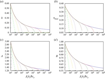
The power-law approximations also provide an opportunity to re-evaluate the velocity profile approximation of Verhoff (Reference Verhoff1963) ((2.43) and (2.44)). Following the approach of Glauert (Reference Glauert1956), the exponent to the skin coefficient of friction is related to the near-wall velocity exponent. For a skin friction coefficient exponent of −1/4, the velocity increases with elevation to the 1/7th power. Figure 6 shows that the selection of 1/7 is Reynolds number specific  $({\beta _r}{h_r}R{e_o}\sim {10^4})$. As the Reynolds number or the relative roughness increase, this exponent shrinks (figure 6a) lowering the elevation of the peak in velocity toward the wall (figure 6b). In essence the boundary layer thins and the inviscid approximation of Phares et al. (Reference Phares, Smedley and Flagan2000) is recovered in the limit of very large jet Reynolds numbers or relative roughness with the peak velocity and perfect slip at the wall and Gaussian decay in velocity therefrom. The approach of the peak velocity toward the wall as the nozzle Reynolds number increases is highlighted in figure 7(a) and shown to be commensurate with prior findings of Poreh et al. (see their figure 3 based on experimental work of Tsuei) (Tsuei Reference Tsuei1962; Poreh et al. Reference Poreh, Tsuei and Cermak1967) and also Rajaratnam & Mazurek (Reference Rajaratnam and Mazurek2005; see their figure 5). The other two parameters in the generalized Verhoff profiles (2.44) are also highlighted in figure 6(c,d), showing that they too depend on the Reynolds number and relative roughness. Figure 7(b) shows that variation in the jet spread is relatively modest, commensurate with the variations cited in the literature (table 1). Indeed, variations in the radial distribution of velocity within the jet nozzle and the velocity decay coefficient play a larger role in the jet spread than do Reynolds numbers or relative roughnesses. We caution, however, that these profiles in figures 6 and 7 only apply to smooth surfaces and some transitionally rough surfaces but not to the fully rough regime.
Scaled velocity profile parameters (a) exponent, b, (b) peak, ηmax, and constants (c) A and (d) B versus the βrhrReo product for k/δr = 0 (bottom solid blue, smooth), 0.0001 (long dashed red), 0.001 (short dash green), 0.01 (dotted brown), 0.1 (short alternating dash purple), 0.3 (long alternating gold) and 1.0 (top alternating double dash bright green).

(a) Radial velocity scaled on peak velocity, fr, and elevation scaled on jet width, η, for  ${\beta _r}{h_r}R{e_o} = {10^4}$ (red short dash), 105 (blue solid) and 106 (green long dash) with k/δr = 0. (b) Jet spread, βr, from (2.27) and (2.44) with hr = 1.1 and ψp = 0.611 from Poreh et al. versus the βrhrReo product for k/δr = 0 (solid blue, smooth), 0.0001 (long dashed red), 0.001 (short dash green), 0.01 (dotted brown), 0.1 (short alternating dash purple), 0.3 (long alternating gold) and 1.0 (alternating double dash bright green).

Summary of jet spreads, βr.

* Vibrating low Reo jets. +They also give βr = 0.06, 0.078 and 0.083 for oblique impingement at 15°, 30° and 45°, respectively.
The skin coefficient of friction appears to be remarkably independent of the standoff distance, H, for the jet data reanalysed here. Both Poreh et al. (Reference Poreh, Tsuei and Cermak1967) and Rajaratnam (Reference Rajaratnam1976) argue that the standoff distance is important within the impingement region (see figure 1a). For the remainder of the wall jet, Poreh et al. argue the standoff distance to be important as encapsulated in a ratio of the standoff distance to the nozzle diameter to a small power based on a Buckingham Pi analysis, but the standoff distance was not varied in their experiments (only diameter in the standoff-distance-to-diameter ratio was). In contrast, Rajaratnam's subsequent Buckingham Pi analysis of additional data sets including that of Poreh et al. argues the influence of the standoff distance to be essentially negligible. In our analysis a dependence on the standoff distance would arise either through the scaled elevation of the maximum in the radial velocity profile or through the βrhrReo dimensionless group. Although the scaled elevation of the maximum in the radial velocity profile in figure 1(b) shows some scatter, a definitive dependence on the standoff distance across multiple data sets is not readily apparent. The jet spread and velocity decay coefficients may be related to the standoff distance through a systematic virtual origin correction, but this effect remains small (approximately 2 nozzle diameters in Rajaratnam's figures 11–14), suggesting that complete resolution of a second-order influence of standoff distance if present must await more careful experimentation.
In summary, we have developed a general expression for the skin coefficient of friction for steady turbulent radial wall jets across smooth and rough surfaces outside of the nearfield impingement region, similar to the Colebrook equation that has been used successfully to evaluate friction factors for flows through smooth and rough pipes for decades. Such a general expression for the skin coefficient of friction has been lacking and resolves inconsistencies across historical power-law expressions. The resulting expression is consistent with both individual measures of the skin coefficient of friction and with prior power-law expressions. Surprising, surface roughness introduces an additional radial dependence that has been unanticipated. This advance has implications for estimating turbulent radial wall jet performance across aging surfaces that become rough over years in industrial service. For example, at the Hanford site, radial wall jets may be used to drive mixing within vessels containing nuclear waste for an intended 40 year lifespan. As the vessels age and surfaces become roughened over time, the skin coefficient of friction will increase limiting mixing far from the impingement point. This expression provides a key ingredient in the analysis of vessel mixing performance.
Acknowledgements
We acknowledge helpful suggestions from L.A. Mahoney and insight from F.F. Erian a superb fluid dynamicist, mentor and friend who passed away from COVID-19 related complications. The authors express appreciation for referees’ comments.
Funding
PNNL is a multiprogram national laboratory operated for the U.S. Department of Energy by Battelle Memorial Institute under Contract DE-AC05-76RL01830.
Declaration of interests
The authors report no conflict of interest.
Data availability statement
Data used in this manuscript are publicly available as cited.
Author contributions
All authors designed the study; A.F. extracted the data sets; L.P. derived the equations; all authors prepared the manuscript.