Introduction
Ultra-wideband (UWB) technology has important applications and good prospects in the broadband ultra-high-speed data transmission and short-distance communication. Nevertheless, UWB systems are susceptible to interference from multipath fading and existing narrow frequency bands, thus affecting the signal transmission quality. Usually, it is a cogent method to reduce the impact of multipath fading by using multiple-input–multiple-output (MIMO) antenna technology. It improves the channel capacity and link quality without increasing the signal power [Reference Gómez-Villanueva and Jardón-Aguilar1]. Furthermore, the overall size of the MIMO antenna swells as the number of elements increases. Thus, there are three basic requirements when designing UWB MIMO antennas: high isolation, compact size, and multiple notches.
In recent years, to address these issues, many researchers have studied the miniaturization technology [Reference Das, Chowdhury and Biswas2–Reference Tripathi, Mohan and Yadav6], decoupling technology [Reference Wang, Du and Yang7–Reference Khan, Iftikhar and Shubair20], and notch technology [Reference Gómez-Villanueva and Jardón-Aguilar1, Reference Gautam, Yadav and Rambabu16, Reference Chandel and Gautam19] of UWB MIMO antennas. The miniaturization technology mainly includes half-cutting technology [Reference Liu, Esselle and Hay3, Reference Ghahremani, Ghobadi and Nourinia4], bending technology [Reference Sun, Fang, Lin and Chuang5], and fractal technology [Reference Tripathi, Mohan and Yadav6]. The decoupling technology comprises a defective ground structure [Reference Wang, Du and Yang7, Reference Chattha, Latif and Tahir8], reasonable layout of antenna elements (orthogonal placement [Reference Dastranj9–Reference Mchbal, Touhami and Elftouh12] and inverted placement [Reference Wang, Du and Yang7]), floor decoupling stubs [Reference Chandel, Gautam and Rambabu13, Reference Thakur, Jaglan and Gupta14, Reference Gautam, Yadav and Rambabu16], neutralization line technology [Reference Zhang and Pedersen17], electromagnetic metamaterials [Reference Wang, Yang and Wang18], etc. Similarly, the notch technology contains etching slots [Reference Gómez-Villanueva and Jardón-Aguilar1, Reference Gautam, Yadav and Rambabu16], loading electromagnetic band-gap structure [Reference Ghahremani, Ghobadi and Nourinia4], embedding parasitic resonance structure [Reference Chandel and Gautam19, Reference Khan, Iftikhar and Shubair20], and so on.
In a previous study [Reference Liu, Esselle and Hay3], the symmetrical half-cut technique was used to reduce the size of the antenna by 49%. Similarly, Ghahremani et al. [Reference Ghahremani, Ghobadi and Nourinia4] employed symmetrical half-cutting technology and appropriately adjusted the position of the antenna feed to achieve a 60% reduction in the size of the antenna. In another report [Reference Wang, Du and Yang7], an MIMO antenna with a size of 50 × 35 mm2 was proposed. It achieved more than 25 dB of isolation by etching the defective ground structure. A four-element MIMO antenna with a size of 58 × 58 mm2 was reported. Furthermore, in an earlier study [Reference Kumar, Urooj and Alrowais15], high isolation (S 21 > 18 dB) was obtained by four orthogonally placed radiators, and a hexagonally shaped complementary split-ring resonator was etched for the dual-band rejection function. In another research study [Reference Wang, Yang and Wang18], two novel metamaterial split-ring resonators were utilized to reduce mutual coupling, which expanded the impedance bandwidth of MIMO antennas at the same time.
A dual-band-notched four-element UWB MIMO antenna based on polarization diversity is presented in this paper. First, the miniaturization of a single UWB antenna is realized using the half-cutting technique. Second, without adding any decoupling structure, the isolation of the MIMO antenna is more than 23 dB in the UWB (excluding the notch band) through the orthogonal polarization diversity technique. Finally, the notch characteristics of the 3.1–3.9 and 5.2–5.9 GHz bands are realized by introducing L-shaped and continuous bending slots of different lengths in the radiation patch. Computer simulation technology (CST) Microwave Studio software was used to perform the simulation and analysis of the MIMO antenna.
Design process and simulation results
Figure 1 displays the final structure of the dual-band-notched four-element UWB MIMO antenna. A single UWB antenna is obtained by symmetrically cutting the traditional circular monopole UWB antenna, as shown in Fig. 2(a). The feed mode of the antenna is a three-segment transmission, and the impedance matching network can be better matched with 50 Ω by adjusting the size of each transmission line. The four antenna elements are placed on the same dielectric substrate in an orthogonal manner to realize the dual polarization characteristics of the MIMO antenna. Subsequently, the rejection band characteristics of WiMAX and WLAN bands are realized by etching slots of different lengths. The designed antenna was printed on a Rogers RT duroid/5880 substrate with a relative permittivity of 2.2, loss tangent of 0.0009, and thickness h = 0.508 mm.
Proposed design structure: (a) antenna structure and (b) side view.

Evolution of the single UWB antenna: (a) original antenna structure and (b) S 11.

UWB antenna element design
In general, if only the change in the effective length of the antenna is considered, the antenna is half-cut at the axis of symmetry, which does not affect its performance. The principle is attributed to the magnetic wall effect at the symmetry plane of the antenna with a symmetric structure; thus, the halved antenna still has the frequency characteristics required by the resonance frequency. Figure 2(a) shows the design process of a single UWB antenna. A miniaturized antenna (#2) can be obtained by halving the original antenna (#1) along the axis of symmetry (SS′). As shown in Fig. 2(b), the reflection coefficient of the halved antenna is significantly worse than that of the original antenna because the input impedance of the halved antenna changes and its resonance frequency is basically unchanged. To improve the impedance matching of the halved antenna, the position of the antenna (#3) on the dielectric substrate is appropriately adjusted. Figure 2(b) shows that #3 has reflection characteristics similar to those of #1, and #3 has a wider operating band.
Band-notch structure design
A 90° clockwise rotation is utilized to create a four-port MIMO array after the basic UWB antenna unit (#3) is designed. Adjacent antenna units are then distributed orthogonally to each other, and the polarization characteristics correspond to orthogonal polarization. In this way, the antenna units can only receive weak signals excited by each other; thus, the isolation of the MIMO antenna is improved. The proposed MIMO antenna structure also exhibits an L-shaped and continuous bending-type slot structure on the radiator, and the direction of the current is opposite in these two slots. The radiated fields caused by the adverse current can cancel each other out, so the antenna cannot radiate efficiently in the notched frequency bands [Reference Chandel, Gautam and Rambabu13].
The length of the two slot structures is related to the center frequency of the notch band, and it can be calculated approximately according to equation (1) [Reference Khan, Iftikhar and Shubair20]:

In equation (1), L is the slot length, c is the speed of light, and ɛ eff and ɛ r are the effective permittivity and relative permittivity, respectively.
According to equation (1), the length of the slot is optimized to be approximately equal to the length of λ/4 (where λ is the free-space wavelength in the notch center frequency). When the antenna operates in the notch frequency band, these slots can be regarded as the λ/4 transmission line with a terminal short circuit at the corresponding frequency, i.e. the parallel resonant circuit. The equivalent circuit of the antenna is shown in Fig. 3(a). Whenever any slot resonates, the input impedance of the antenna at the corresponding notch band approaches infinity. At this time, the resonant circuit is equivalent to an open circuit, and the antenna cannot transmit energy normally; thus, a notch band is generated. In Table 1, the calculation and simulation slot length values when the notch center frequencies are 3.5 and 5.5 GHz, respectively, are compared. Table 1 shows that the difference between the two values is very small.
Comparison between the simulated S 11 of antenna by CST and by the equivalent circuit model: (a) equivalent circuit model and (b) S 11.

Comparison of theoretical value and simulation value of slot length

Figure 3(b) shows a comparison between S 11 of the proposed antenna obtained by CST simulation and the equivalent circuit model. As shown in the figures, the trends of the curves agree reasonably well over the UWB band, especially in the dual-notched frequency bands. The discrepancy between the curves can be mostly attributed to the antenna that is replaced by a 50 Ω resistance in the equivalent circuit. In most cases, if the antenna is well matched, this approximation can be valid, but for a large bandwidth this hypothesis is not fulfilled.
All the parameters of the proposed antenna were optimized using commercial full-wave software CST Microwave Studio. The final detailed dimensions of the UWB MIMO antenna, in millimeters, are as follows: W = 42, W 1 = 12, W 2 = 1.5, W 3 = 1.2, W 4 = 0.4, W 5 = 0.2, W 6 = 2, W 7 = 6, L = 42, L 1 = 14.65, L 2 = 8, L 3 = 4.3, L 4 = 2, L 5 = 8.8, L 6 = 2, L 7 = 30, R = 7.7, h = 0.508.
Simulated and experimental results and analysis
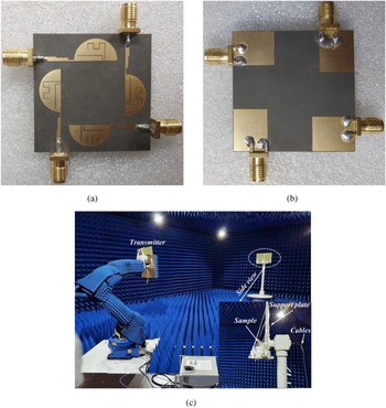
The fabricated antenna prototype and the test environment are shown in Fig. 4. The 3671E vector network analyzer (China Electronics Technology Instruments Limited Company) was used to test parameters, such as S-parameters and isolation.
Photograph of the fabricated antenna: (a) top view, (b) bottom view, and (c) test environment.

S 11-parameters
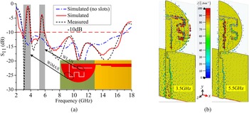
The simulated and measured S 11 of the antenna prototype is given in Fig. 5(a), showing similar trends. The measured −10 dB impedance bandwidth is 2.9–16.5 GHz (relative bandwidth is about 140.2%), which is close to the simulated result (2.7–16.7 GHz, relative bandwidth is about 144.3%). The notch frequency bands of the MIMO antenna are 3.1–3.8 and 5.2–5.9 GHz. In addition, Fig. 5(a) also depicts the S 11 of the slotless MIMO antenna, and the results are acceptable.
S 11 and simulated surface current distribution of MIMO antenna: (a) S 11 and (b) surface current distribution.

Figure 5(b) shows the simulated surface current distribution of the antenna at 3.5 and 5.5 GHz. Near the center frequency of the notch, a large number of currents in the opposite directions are confined along the slot structure, the electromagnetic energy cannot be completely radiated outward, and the notch function occurs [Reference Chandel, Gautam and Rambabu13, Reference Gautam, Yadav and Rambabu16]. Nevertheless, the current is evenly distributed in the non-notched frequency band, and the antenna energy is normally radiated outward.
To analyze the effect of slits on the band-notched characteristics, various parameters were assessed. First, the length of the notch antenna, slot 1, is varied to show the effect of the overall length of slot 1 on the WiMAX band-notched frequency in Fig. 6(a). As the figure shows, when the length of slot 1 is shifted from 16.8 to 18 mm, the notch band shifts toward a lower frequency. Therefore, to obtain the desired band-notched frequency, 17.4 mm is chosen as the final value. Similarly, Fig. 6(b) shows the S-parameters for the variation of length slot 2, while other parameters remain constant. As the length of slot 2 increases from 10.5 to 11.5 mm, the center of the notched frequency band shifts from 5.9 to 5.3 GHz. Therefore, 11 mm is chosen as the final value of the slot 2 length. Both values are approximately the same, which confirms the effectiveness of equation (1).
Effects of the length variation of the slits on S 11: (a) slot 1 and (b) slot 2.

Isolation
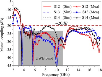
Figure 7 shows the measured and simulated isolation of the MIMO antenna when port 1 is excited and the other three ports are terminated with 50 Ω matched loads. In the UWB frequency band, the couplings between ports 1 and 2 and that between ports 3 and 4 are less than −23 dB, but the coupling in the notch band is only less than −20 dB. This is because there is substantial energy accumulation in the notch frequency band and this energy cannot be radiated outward, which leads to the increase of the coupling between antenna elements. Because of the symmetrical geometry of the structure, the same characteristics appear when the other three ports are activated.
Isolation of the UWB MIMO antenna.

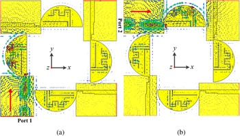
To understand the decoupling effect of the polarization diversity technology intuitively, Fig. 8 shows the simulated surface current distribution of the MIMO antenna at 10 GHz. When port 1 is excited, the surface current flows along the y-axis direction and forms a y-polarized field. Therefore, the surface current coupled to the other three antenna elements is very weak. Similarly, when port 2 is excited, the surface current flows in the x-direction, forming an x-polarized field. A large amount of current is concentrated in this antenna element, while the other three antenna elements have weak surface currents. The polarization diversity technology can effectively improve the isolation of MIMO antennas.
Simulated surface current distribution on the antenna at 10 GHz: (a) port 1 is excited and other ports are matched and (b) port 2 is excited and other ports are matched.

Radiation characteristics
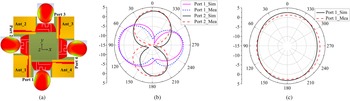
In a MIMO system, multiple antenna elements with different radiation patterns can be employed to reduce the multipath effects. Figure 9(a) shows the three-dimensional (3D) radiation pattern of the MIMO antenna when ports 1–4 are excited at 5 GHz. As shown in the figure, the radiation patterns of Ant_1 and Ant_3 are 180° mirror images, and the radiation patterns of Ant_1 and Ant_2 are perpendicular to each other. Furthermore, Ant_2 has a good omnidirectional radiation mode in the yoz-plane, and a radiation pattern similar to the “8”-shape in the xoz-plane. In addition, the two-dimensional (2D) radiation patterns of Ant_1 and Ant_2 in the xoy-plane at 5 GHz are plotted in Fig. 9(b). The results show that the radiation patterns of ports 1 and 2 in the xoy-plane are also perpendicular to each other. Furthermore, Ant_1 has stronger radiation at 90° and 270°, whereas Ant_2 has null radiation in those directions. The above results verify that the proposed MIMO antenna has good diversity performance. Figure 9(c) shows that the pattern is nearly omnidirectional in the xoz-plane, which is suitable for UWB MIMO systems.
3D and 2D patterns of the antenna when exciting different ports: (a) 3D pattern, (b) xoy-plane, and (c) xoz-plane (only port 1 is excited, while the other ports are terminated with a 50 Ω load).

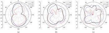
To illustrate the radiation stability of the proposed antenna, Fig. 10 shows the simulated radiation patterns of the antenna at 8, 11, and 14 GHz when port 1 is excited, while the other port is terminated with a 50 Ω load, and vice versa. At lower frequencies, the patterns were fairly “8”-shaped in the xoy-plane and omnidirectional in the xoz-plane, as shown in Figs 9(b) and 10(a) at 5 and 8 GHz. At higher frequencies, radiation patterns deteriorate at higher frequencies owing to the splitting of the radiation lobes. The deterioration is caused by an imbalance in the high-frequency current distribution [Reference Wang, Du and Yang7].
Simulated radiation patterns of the MIMO antenna: (a) 8 GHz, (b) 11 GHz, and (c) 14 GHz.

Figure 11 shows that, in the operating band, the maximum gain of the antenna is approximately 5 dBi. In the notch band, the gain plummets to −2 dBi, which effectively solves the problem of electromagnetic compatibility among the UWB, WiMAX, and WLAN. The radiation efficiency of the antenna also has the same variation trend.
Gain and efficiency of the UWB MIMO antenna.

MIMO performance parameters
In a MIMO antenna system, the envelope correlation coefficient (ECC) is used to evaluate the diversity performance. In an ideal uniform scattering environment, S-parameters – equation (2) – are often used to calculate the ECC [Reference Tripathi, Mohan and Yadav6, Reference Dastranj9]. However, the calculated ECC is closer to the actual situation with the far-field parameters – equation (3) [Reference Wang, Du and Yang7]:


where i and j are the numbers of ports, XPR is the cross-polarization ratio, and $P_\theta$ and $P_\phi$
 are the θ and ϕ components of the angular density functions of the incoming wave, respectively.
The diversity gain (DG) is also an important parameter for evaluating the performance of a MIMO antenna. The DG can be calculated using equation (4). Figure 12 shows, except for the dual-notch frequency band, the ECC is lower than 0.004, and the DG is higher than the 9.9 dB for the MIMO antenna, proving that the antenna has a good diversity characteristic:
Simulated ECC and DG of the proposed design.


Table 2 lists the performance parameters of MIMO antennas that have been reported in the literature, and compares them with those of the proposed antenna. Compared with those in the literature [Reference Rajkumar, Amala and Selvan10, Reference Mchbal, Touhami and Elftouh12], although the antenna in this study has a larger size, it has the advantages of high isolation and a simple structure (without using any decoupling structure). In addition, compared with previously reported ones [Reference Tripathi, Mohan and Yadav6, Reference Khan, Iftikhar and Shubair20], the design here has obvious advantages in terms of size and isolation, but the previous antennas [Reference Tripathi, Mohan and Yadav6, Reference Khan, Iftikhar and Shubair20] have better low-frequency performance. Although a previously designed antenna [Reference Dastranj9] is smaller, it is a two-element MIMO antenna. The maximum gains in previous reports have been shown in Table 2. Compared with those reported earlier [Reference Tripathi, Mohan and Yadav6, Reference Pannu and Sharma11, Reference Mchbal, Touhami and Elftouh12], the proposed antenna has a higher gain. Moreover, Table 2 shows the related parameters of the MIMO antennas (#1MIMO and #3MIMO) designed with a full antenna (#1) and a halved antenna (#3) as a single antenna. In the comparison, #3MIMO has great advantages in terms of size and isolation.
Performance comparisons with previously reported antennas

Conclusion
A compact (42 × 42 mm2) dual-band-notched four-element UWB MIMO antenna was proposed. A single UWB antenna was miniaturized using half-cut technology. On the one hand, the orthogonal diversity technique was used to enhance the isolation of the MIMO antenna, which can significantly improve the isolation (S 21 > 23 dB) of the MIMO antenna without adding other decoupling structures. On the other hand, two slots with different lengths were etched on the radiator to realize the band rejection characteristics of the WiMAX and WLAN frequency bands. In addition, the advantages of orthogonal placement were analyzed using the 2D and 3D radiation patterns.
Acknowledgements
This study was supported in part by the National Natural Science Foundation of China under Grants 61701398 and 61771389, and in part by the Shaanxi Key Laboratory of Complex System Control and Intelligent Information Processing, China under Grant 19JS050.
 Zhonghong Du received his B.S. in Electronic Information from Hexi University, Zhangye, China in 2017 and his M.S. in Communicating Engineering from the Xi'an University of Technology, Xi'an, China in 2020. He is currently pursuing his Ph.D. degree with the Department of Electronic Engineering, Xi'an University of Technology. His research interests include MIMO antennas decoupling technology, electromagnetic metasurface, and RF circuits.
 Xiaohui Zhang received his B.S. in Industrial Automation in 1995, his M.S. in Control Science and Engineering in 2002, and his Ph.D. degree in Control Science and Engineering in 2009, all from the Xi'an University of Technology, Xi'an, China. He is currently a Professor of Information and Control Department at the Xi'an University of Technology, Xi'an, China. His recent research interests include advanced navigation, signal processing and pattern recognition, electromagnetic technology, and antenna design.
 Peiyu Qin received her B.S. in Information Engineering from Tianjin Normal University, Tianjin, China in 2019. She is currently a graduate student at the Xi'an University of Technology, Xi'an, China. Her current research interests include electromagnetic metasurface and MIMO antennas.
 Yanning Yuan received her B.S. in Electronic Information from Liaoning Shihua University, Fushun, China in 2004 and her M.S. in Communicating Engineering from the Xi'an University of Technology, Xi'an, China in 2007. She subsequently joined the Shaanxi Lingyun Science and Technology Co., Ltd. and served as a project manager. She is currently a full-time researcher at the Xi'an University of Technology, Xi'an, China. Her research interests include ultra-wideband antennas, multi-frequency antennas, and RF circuits.
 Jiangfan Liu (M’16) received his B.S. and M.S. degrees in Electronic Engineering from the Xi'an University of Technology (XUT), Xi'an, China, in 2006 and 2009, respectively, and his Ph.D. degree in Electronic Engineering from Northwestern Polytechnical University, Xi'an, in 2013. He is currently an associate professor with the Department of Electronic Engineering, XUT. His current research interests include computational electromagnetics and antenna design.
 Xiaoli Xi received her B.S. in Applied Physics from the University of Defense Technology in Changsha, China in 1990, her M.S. in Biomedical Engineering from the Fourth Military Medical University in Xi'an, China in 1998, and her Ph.D. degree in Electrical Engineering from the Xi'an Jiaotong University in Xi'an, China in 2004. She is currently a Professor at the Department of Electrical Engineering at the Xi'an University of Technology, Xi'an, China. Her recent research interests include antenna design, radio wave propagation and advanced navigation, and electromagnetic technology.