
Introduction
High entropy alloys (HEAs) known for unique alloy design concept of multi-component alloys with equiatomic or near-equiatomic compositions,[ Reference Cantor, Chang, Knight and Vincent 1 , Reference Zhang, Zuo, Tang, Gao, Dahmen, Liaw and Lu 2 ] have attracted the attention of scientific researcher because of excellent performance, such as high temperature stability, low temperature toughness, superior corrosion resistance and simple structure,[ Reference Murty, Yeh and Ranganathan 3 – Reference Kao, Chen, Chen and Yeh 6 ] which impart them great potential of high-temperature structural material. Thus it is a crucial issue for the study of structure stability.[ Reference Miracle 7 ]
HEAs are characterized by face-centered cubic (FCC), body-centered cubic (BCC) or other simple solid solutions rather than intermetallic compounds owing to high configurational entropies, because of which they were thought to be thermodynamically stable.[ Reference Yeh, Chen, Lin, Gan, Chin, Shun, Tsau and Chang 8 ] However, with the in-depth study of HEAs, researchers found that some ordered solid solution or intermetallic compounds could precipitate from the matrix.[ Reference Pickering, Muñoz-Moreno, Stone and Jones 9 , Reference Choudhuri, Alam, Borkar, Gwalani, Mantri, Srinivasan, Gibson and Banerjee 10 ] For example, CoCrFeMnNi alloy was once widely considered as a stable HEA at any temperature below its melting point, but M23C6 and σ phases were found after prolonged exposures at 700 °C afterwards.[ Reference Pickering, Muñoz-Moreno, Stone and Jones 9 ] Recently researchers reevaluated the stability of CoCrFeMnNi alloy and results show that more phases could precipitate at the grain boundaries after longtime anneals at 500–900 °C.[ Reference Otto, Dlouhý, Pradeep, Kubenov, Raabe, Eggeler and George 11 ] Even the CoCrFeNi HEA was demonstrated to be instable.[ Reference He, Wang, Wu, Li, Wang and Liu 12 ] Actually, it is the competition between the entropy depending on the disordering of elements and enthalpy, which really determines the type of phases,[ Reference Zhang, Zuo, Tang, Gao, Dahmen, Liaw and Lu 2 , Reference Rao, Diao, Ocelik, Vainchtein, Zhang, Kuo, Tang, Guo, Poplawsky, Zhou, Liaw and De Hosson 13 ] but it rarely occurs in metallic solution since different atoms occupying random lattice positions.[ Reference Miracle and Senkov 14 ] After solidification, elemental segregation takes place in some HEAs even though the x-ray diffraction (XRD) patterns cannot detect the formation of any new phase.[ Reference An, Jia, Wu, Rack, Patchen, Liu, Ren, Li and Liaw 15 – Reference Wang, Wang, Wang and Yeh 18 ] That is to say, different areas own different entropies. Thus the phases will change under the proper temperature in subsequent heat treatment, which gives HEA more chance to possess abundant phases rather than simple solid solution structure.
AlxCoCrFeNi is a widely studied five-component HEA system and the structure changes from single FCC, then FCC + BCC, and finally to single BCC with Al contents increasing.[ Reference Kao, Chen, Chen and Yeh 6 ] The evolution of microstructure, mechanical, thermophysical, and electrical properties of AlxCoCrFeNi alloy have been reported in the literature.[ Reference Kao, Chen, Chen and Yeh 6 , Reference Wang, Wang, Wang and Yeh 18 – Reference Niu, Kou, Guo, Zhang, Wang and Li 21 ] However, the hexagonal closed-packed (HCP) structure has never been found in the AlxCoCrFeNi alloy system. Even with the same material and similar heat treatment, XRD patterns show Al0.5CoCrFeNi keeps a FCC + BCC two-phase structure after aged for 0.5–8 and 24 h.[ Reference Lin and Tsai 4 , Reference Niu, Kou, Guo, Zhang, Wang and Li 21 ] Therefore, in this study, the nanoscale HCP phase is for the first time found in Al0.5CoCrFeNi HEA by means of transmission electron microscopy (TEM) and the transition mechanism of BCC-HCP is discussed.
Experimental procedures
The Al0.5CoCrFeNi button ingots, each weighting about 30 g, were prepared by arc-melting under argon atmosphere. The purity of raw material (Al, Co, Cr, Fe, and Ni) is more than 99.95%. Each ingot was inverted and re-melted for four times in order to improve the chemical homogeneity. Then button ingots were cleaned with ethanol and suction-cast into a plate (50 × 20 × 3 mm3) in a water-cooled split Cu mold. The plate samples were annealed at 650 °C for 8 h under air atmosphere followed by water-quenching to investigate the microstructure evolution. The microstructures were characterized by TEM (Tecnai F30 G2) equipped with an energy-dispersive spectrometry (EDS) analysis.
Results and discussion
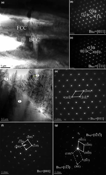
Figure 1 displays the constituent phases of as-cast and 650 °C/8 h heat-treated Al0.5CoCrFeNi HEA, including the bright field image and corresponding selected area electron diffraction (SAED) patterns. From Figs. 1(a)–1(c), the conclusion that as-cast Al0.5CoCrFeNi is a double-phase alloy can be obtained. After heat-treatment at 650 °C for 8 h, the SAED patterns shown in Figs. 1(e) and 1(f) are corresponding to [011] zone-axis of FCC phase and [001] zone-axis of B2 phase, which indicate that the position 1 and 2 in Fig. 1(d) is FCC and B2 phases, respectively. Figure 1(g) shows the [1
 $\bar 2$
1
 $\bar 3$
] zone-axis of HCP phase and [1
 $\bar 1\bar 3$
] zone-axis of BCC phase, which confirms that the precipitates located at interdendritic region, marked as position 3, possess an HCP structure. The chemical composition of HCP phase consists of Al 9.36 at.%, Cr 21.09 at.%, Fe 22.07 at.%, Co 27.43 at.%, and Ni 20.02 at.% from the EDS analysis results, indicating HCP phase a Co-rich phase. Previous research has proven that the solubility of Co in the Ni, Al-rich interdendritic region,[Reference Lin and Tsai
4
,
Reference Kao, Chen, Chen and Yeh
6
] which can be confirmed as NiAl-based solid solution, is higher than those of other elements because of the negative enthalpy of mixing of Al-Ni and Al-Co binary systems.[
Reference Wang, Wang, Wang and Yeh
18
,
Reference Wang, Wang and Yeh
22
,
Reference Zhang, Wu and Dai
23
] So the HCP phase, rich in Co, was obtained during the decomposition of the interdendritic region. It needs to be emphasized that we have conducted a lot of orthogonal heat-treatment experiments about Al0.5CoCrFeNi. The annealing temperature is 450, 650, 850 °C and the holding time is 30 min, 1, 2 ,4, and 8 h, relatively. Only in 650 °C/8 h, can HCP phase be detected by TEM.
(a) Bright field image of as-cast Al0.5CoCrFeNi HEA. (b, c) Corresponding selected area electron diffraction patterns. (d) Bright field image of Al0.5CoCrFeNi HEA for 650 °C/8 h heat-treated condition. (e–g) Corresponding selected area electron diffraction patterns of position 1, 2, and 3.
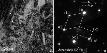
In order to further study the formation of HCP phase, the interdendritic region is specially observed. TEM bright-image of interdendritic region in Al0.5CoCrFeNi HEA is shown in Fig. 2(a). The micrograph reveals a second phase with lath-shaped morphology and dimensions of ~40 nm in width as indicated by the white arrows. The selected area electron diffraction pattern in Fig. 2(b) confirms that an HCP structure precipitates from the BCC phase. According to the binary phase diagram of Co-Cr, Co-Fe, and Co-Ni,[
Reference Zhang, Zhang, Chen, Zhu, Cao and Kattner
24
,
Reference Li, Mao, Korzhavyi and Selleby
25
] the HCP phase can be found under 650 °C suggesting that it is conceivable for the appearance. Meanwhile, the orientation relationship between BCC and HCP phases is determined as [11
 $\bar 2$
0]hcp || [111]bcc. High resolution transmission electron microscopy (HRTEM) of the area indicated by the white circle is studied later so as to analyze the formation mechanism of the HCP phase.
(a) TEM bright-image of interdendritic region in Al0.5CoCrFeNi HEA. (b) Corresponding selected area electron diffraction pattern.
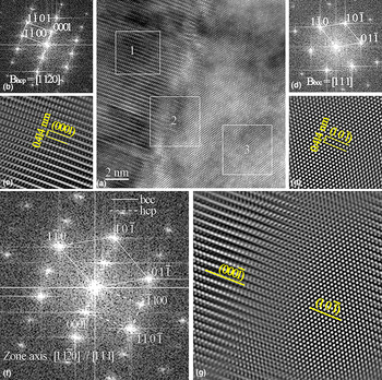
The crystal lattice image of BCC and HCP phase obtained by high resolution TEM is shown in Fig. 3(a). Figures 3(b) and 3(c) show the corresponding fast Fourier transformation (FFT) and inverse fast Fourier transformation (IFFT) electron diffraction patterns (EDPs) of square 1 with the zone-axis of [11
 $\bar 2$
0]hcp, respectively. Lattice constant of the HCP phase is calculated as 0.254 nm in Fig. 3(b), and the interplanar distance of (0001)hcp in Fig. 3(c) is 0.414 nm. The FFT and IFFT EDPs of square 3 with the zone axes of [111]bcc are shown in Figs. 3(d) and 3(e). The lattice constant of BCC phase is calculated to be 0.293 nm and the interplanar distance of (10
 $\bar 1$
)bcc is also 0.414 nm. The FFT and IFFT EDPs of interface indicated by square 2 are shown in Figs. 3(f) and 3(g). It is interesting to note that the two phases (HCP and BCC) obey an orientation relationship of the type [11
 $\bar 2$
0]hcp || [111]bcc, (000
 $\bar 1$
)hcp || (10
 $\bar 1$
)bcc. Apparently, the interface is coherent, which can play a significant role in improving the mechanical behavior.[
Reference Welk, Williams, Viswanathan, Gibson, Liaw and Fraser
26
,
Reference Fan, Li and Zhang
27
] Therefore, Fig. 3 intuitively proves that the HCP structure was transformed from the BCC structure during 650 °C/8 h heat-treatment. However, the total volume fraction of this nanoscale HCP phase is tiny because even the volume fraction of interdendritic regions in Al0.5CoCrFeNi is no more than 10% after heat treatment at 650 °C for 8 h according to our previous study.[
Reference Niu, Kou, Guo, Zhang, Wang and Li
21
] This is the main reason why HCP phase was not detected by XRD in Al0.5CoCrFeNi HEA before.[
Reference Lin and Tsai
4
,
Reference Chou, Chang, Chen and Yeh
19
]
HRTEM and corresponding selected area FFT and IFFT images of Al0.5CoCrFeNi HEA after heat treatment (8 h at 650 °C). (a) HRTEM image of bcc and hcp phases. (b, c) The corresponding FFT and IFFT images of square 1. (d, e) The corresponding FFT and IFFT images of square 3. (f, g) The corresponding FFT and IFFT images of square 2.
Until now, the most common mechanism used to explain the BCC–HCP transformation in BCC-typed metals or alloys is come up by Burgers.[
Reference Burgers
28
] The detailed transformation process has been reported elsewhere[
Reference Ojha and Sehitoglu
29
,
Reference Yoshinaga, Morozumi, Portevin and Chatelier
30
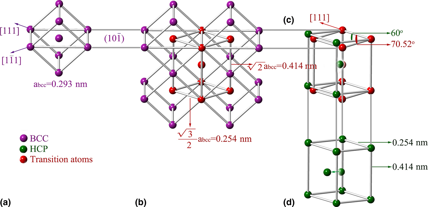
]. However, the BCC–HCP transformation in Al0.5CoCrFeNi alloy in this paper can occur without compression or dilatation as illustrated, which is the difference from the Burgers mechanism. In Fig. 4(a), a BCC unit-cell is in a position that a definite (10
 $\bar 1$
)-plane is perpendicular to the plane of the paper. The lattice constant is 0.293 nm known from the above calculation. The [111] and [1
 $\bar 1$
1] directions are marked in (10
 $\bar 1$
)-plane. Five unit-cells like Fig. 4(a) can make up the lattice model in Fig. 4(b) and a prismatic cell is marked specially. The height of the prismatic cell is 0.414 nm calculated from
 $\sqrt 2 $
abcc (abcc = 0.293), which is in agreement with the result in Fig. 3(e). The sides of the prismatic cell are 0.254 nm, which are parallel to [111]-direction and [1
 $\bar 1$
1]-direction in the (10
 $\bar 1$
)-plane. Figure 4(c) shows the migration of atoms from a prismatic cell to another centered cell. The direction and distance of migration need to be confirmed in order to change the angle of 70o32’ between the [111]-direction and [1
 $\bar 1$
1]-direction to 60o. From Figs. 3(c) and 3(e), the interplanar distance of (0001)-plane and (10
 $\bar 1$
)-plane is equal suggesting that the atoms move only in (10
 $\bar 1$
)-plane. In fact, the question is that how a rhombus with the angle of 70o32’/109o28’ transforms into another rhombus with the angle of 60o/120o. The atoms in prismatic plane can move along [111]-direction of (1
 $\bar 2$
1)-plane, which is perpendicular to the (10
 $\bar 1$
)-plane. The distance is calculated to be 0.0466 nm
 $(2\sin \;(10.52/2) \times \sqrt 3 a_{{\rm bcc}} /2)$
. Figure 4(d) shows the unit-cell of the HCP structure. It has a height of 0.414 nm and the side of rhombus is 0.254 nm. In order to obtain an atomic arrangement similar to that in the HCP lattice, the central atoms must migrate to the central position of the triangle included in rhombus. This can be realized by a shift parallel to the [101]-direction of (10
 $\bar 1$
)-plane and the distance is calculated to be 0.0733 nm. It should be emphasized that the atoms in every two adjacent basal plane must migrate a same distance towards the same direction.
Transformation of the BCC structure into the HCP structure in Al0.5CoCrFeNi HEA. (a) A BCC unit-cell in such a position that a definite (10
 $\bar 1$
)-plane is perpendicular to the plane of the paper. (b) A lattice model made up by five unit-cells like A. (c) The migration of atoms from a prismatic cell to another centered cell. (d) The unit-cell of the HCP structure.

Conclusions
In this work, we firstly prove the existence of an HCP phase in Al0.5CoCrFeNi HEA after heat-treatment at 650 °C for 8 h. The Co-rich HCP phase located in the interdendritic region of Al0.5CoCrFeNi HEA is transformed from the BCC structure through simple shear, and the two phases (HCP and BCC) obey an orientation relationship of the type [11
 $\bar 2$
0]hcp || [111]bcc, (000
 $\bar 1$
)hcp || (10
 $\bar 1$
)bcc.
Acknowledgments
Authors are grateful to X.Y. Gao for expert TEM characteristic. This study was financially supported by the National Natural Science Foundation of China (Grant No. 51571161), the Natural Science Basic Research Plan in Shaanxi Province of China (NO. 2016JQ5003) and State Key Laboratory of Solidification Processing (NO. SKLSP201505) of Northwestern Polytechnical University.