1. Introduction
As science and technology rapidly advance, firefighting robots are increasingly vital in firefighting and rescue operations. Confronted with dangers like oxygen deficiency, extreme heat, and heavy smoke, firefighting robots can support or replace firefighters in rescue missions, ensuring their safety [Reference Sherstjuk, Zharikova and Sokol1]. Currently, most firefighting robots are remotely controlled by firefighters to access fire scenes, utilizing onboard sensors (such as visual and infrared sensors) to assist in gathering site information, thus aiding firefighting and rescue operations. Nevertheless, achieving autonomous firefighting continues to be a significant challenge for firefighting robots.
For the research and development of firefighting robots, after two stages of development, the first generation of program control and the second generation of sensory manipulation, it is moving toward the third generation of intelligent stage [Reference Cheng, Yang and Li2], and now the main direction is to improve the intelligence and autonomy of the robot [Reference Wilk-Jakubowski, Harabin and Ivanov3]. At present, the autonomous navigation of robots is often realized by multi-sensor Simultaneous Localization and Mapping (SLAM) algorithms mainly based on LiDAR [Reference Shamsudin, Ohno, Hamada, Kojima, Westfechtel, Suzuki, Okada, Tadokoro, Fujita and Amano4–Reference Zhang, Wang, Tian, Yao and Zhao9]. However, LiDAR-based systems suffer from low update rates and limited semantic understanding, making them less adaptable to dynamic and unstructured fireground environments. In contrast, visual sensors offer richer environmental information and higher frequency, which are essential for rapid response in firefighting tasks. Therefore, developing a visual-SLAM system that is robust to visual degradation, dynamic scenes, and flame interference is crucial for enabling autonomous navigation in firegrounds.
To this end, this paper proposes a visual SLAM framework called Fire SLAM, which tightly integrates real-time flame detection, tracking, and SLAM. The system enhances navigation accuracy in the presence of dynamic flame disturbances and reduces the influence of flame regions through dynamic feature filtering in SLAM processing. This study primarily provides three theoretical contributions:
-
(1) This paper designs a real-time 3D flame perception method based on object detection and image segmentation algorithms, which effectively reduces algorithm complexity through clustering and sampling flame regions.
-
(2) Based on the results of flame detection, this paper achieves flame tracking of ordinary frames by Kalman filter. Furthermore, based on the flame region, dynamic filtering of feature points is performed, and static feature points are used for pose estimation and loop closure, resulting in significantly improved localization robustness in fire scenes.
-
(3) This paper builds a hardware platform and various experimental setups to collect data, creating an image dataset and image sequence dataset containing flame targets, which are used for training the deep learning algorithms employed in this study, as well as for experimental validation of the flame localization and SLAM algorithms. Experiments on both real-world and simulated fire scenarios demonstrate the effectiveness of the proposed Fire SLAM system under flame dynamics conditions.
The remainder of this paper is organized as follows: Section 2 discusses related work. Section 3 describes the details of the proposed algorithm. Section 4 provides a detailed description of the hardware platform, experimental setups, collected datasets, experimental procedures, and results. Lastly, a summary of the paper is presented, along with suggestions for future research directions.
2. Related work
2.1. VSLAM algorithm
To achieve autonomous robot localization, numerous scholars have conducted extensive research on visual SLAM (Simultaneous Localization and Mapping) and VO (Visual Odometry) algorithms. DSO [Reference Engel, Koltun and Cremers10] is a classic direct monocular VO method that estimates camera pose by minimizing photometric error over selected pixel patches. While efficient, it is highly sensitive to illumination changes and dynamic objects, limiting its use in unstructured or volatile environments such as firegrounds. SVO [Reference Forster, Zhang, Gassner, Werlberger and Scaramuzza11] is a hybrid VO algorithm that combines direct pose initialization and sparse feature-based refinement. Although optimized for speed, SVO suffers from degraded performance under challenging visual conditions and often struggles with robustness in complex scenes. The ORB-SLAM series [Reference Raúl Mur-Artal and Tardós12–Reference Campos, Elvira, Rodríguez, Montiel and Tardós14] is widely used feature-based SLAM frameworks that leverage ORB features [Reference Rublee, Rabaud, Konolige and Bradski15] for tracking, mapping, and loop closure in monocular, stereo, and RGB-D setups. These methods achieve high accuracy but incur substantial computational overhead and are prone to drift in dynamic environments, such as those with moving fire or smoke.
OV
 $^{2}$
SLAM [Reference Ferrera, Eudes, Moras, Sanfourche and Besnerais16] improves upon these limitations by restricting heavy computations like feature extraction to keyframes. It tracks intermediate frames using lightweight photometric optimization and performs local mapping via feature descriptors only on selected frames. This allows OV
 $^{2}$
SLAM to balance accuracy and speed while retaining robustness to visual disturbances and small occlusions.
In recent years, considerable progress has been made in addressing the challenges of visual SLAM in dynamic environments. For example, CPR-SLAM [Reference Yu, Zheng and Ou17] enhances RGB-D SLAM performance by leveraging sub-point cloud correlations to mitigate dynamic interference. Shen and Zhang [Reference Shen and Zhang18] proposed a dynamic SLAM framework that integrates YOLOv7-based segmentation with geometric constraints to effectively manage indoor object motion. Similarly, Zhang et al. [Reference Zhang, Dong, Guo, Ye, Gao, Xiang, Chen and Wu19] introduced a semantic SLAM system that employs an improved Mask R-CNN to filter out dynamic regions in complex environments.
While these approaches have significantly advanced SLAM robustness in general dynamic settings, they do not specifically address the unique challenges posed by flame interference or the need for fire-specific perception, both of which are critical for robotic operations in firefighting scenarios.
To this end, this paper adopts OV
 $^{2}$
SLAM as the foundation and extends it with a flame perception module to improve localization performance in fire scenes.
2.2. Flame detection and segmentation algorithm
Early fire detection systems relied on infrared or gas sensors [Reference Skrbek, Briess, Oertel, Lorenz, Walter and Zhukov20, Reference Guan-lin21], which required proximity activation and provided limited environmental context. These systems were often unreliable in dynamic or cluttered environments.
To overcome these issues, researchers have employed visual sensors for flame detection, initially using handcrafted feature-based methods [Reference Li, Mihaylova, Isupova and Rossi22–Reference Zaman, Hasan, Ahmed and Ashfaq27]. These techniques extract visual cues (e.g., color, shape, motion) for flame detection and are favored for their low cost and broad monitoring coverage. However, their performance is sensitive to ambient lighting, occlusion, and parameter tuning, which limits generalization.
With the rapid advancement of deep learning, flame detection has significantly benefited from CNN-based models [Reference Wenzheng and Jie28–Reference Kong, Jin, Li and Kim32]. These methods eliminate manual feature design and exhibit superior performance under diverse conditions. Notably, lightweight detection models like YOLOv8n strike a balance between inference speed and accuracy, making them suitable for real-time onboard deployment in mobile robots.
Despite progress in flame detection and SLAM research, respectively, few works have explored their integration into a unified robotic perception framework for firefighting tasks. Therefore, this paper proposes a novel SLAM algorithm based on OV
 $^{2}$
SLAM, enhanced with a flame detection and localization thread. In this thread, keyframes are used for flame segmentation and 3D localization, while regular frames employ Kalman filtering to track flame regions. The flame detection results are then used to filter out dynamic feature points in the SLAM frontend, enabling more reliable pose estimation and loop closure.
This integrated design enables real-time operation, improves robustness in dynamic fire scenes, and enhances the robot’s perception of flames, addressing limitations of existing SLAM frameworks when deployed in fire-prone environments.
3. Method
3.1. System overview
This article proposes a visual SLAM method for firefighting robots in fire scenarios, which synchronously detects flames, locates 3D objects, and establishes maps for the robot itself. The algorithm in this article is developed based on the ov2slam algorithm, with the addition of a flame detection and localization thread. In this thread, the improved YOLOv8n algorithm is used to achieve flame detection and 3D localization functions. Furthermore, based on the results of flame detection, the feature points extracted in the feature extraction thread are dynamically filtered, and the static features obtained are used to calculate the robot pose and perform loop detection, thereby improving the positioning accuracy of the algorithm. The framework of the algorithm is shown in Figure 1.
The overall framework of the algorithm: The input of the algorithm is stereo images, and the output of the algorithm is 3D localization of the flame, the pose of the robot itself, and sparse flame semantic point cloud map.

For images captured by the stereo camera, one input is directed to the flame detection and localization thread to perform flame detection and 3D localization, outputting the 2D coordinates of flame bounding boxes and the 3D coordinates of the flame centroid. On the other hand, the images are input into the visual frontend thread to extract feature points. Then, based on the flame bounding boxes, feature points are dynamically filtered to retain static feature points for pose estimation and loop closure detection. This achieves robot pose computation and loop closure detection. Finally, in the mapping thread, the flame centroid is marked, and a flame semantic map is constructed.
3.2. Flame detection and segmentation algorithm
In this study, building upon our prior research [Reference Ding, Yang, Li, Hua and Mu33], we implement flame detection and segmentation using an enhanced version of the YOLOv8n algorithm. This improved approach aims to achieve higher precision and efficiency in identifying and delineating flame regions within complex environments.YOLOv8 dynamically scales the backbone network’s parameter size by configuring three key factors: depth (d), width (w), and scale (r). Based on these factors, the model is categorized into five distinct levels: n, s, m, l, and x, with each subsequent level exhibiting an increase in both parameter count and computational demand. Given the constraints of computational resources in real-world production environments, it is essential for the optimized network to maintain lower parameter and computational complexity. This ensures enhanced detection speed and improved deployment efficiency on platforms with limited computing capabilities. To strike an optimal balance between detection accuracy and processing speed, the YOLOv8n network is selected as the foundation for further improvements.
In this study, we enhance the YOLOv8n network by replacing traditional strided convolution with SPD Conv, which effectively reduces computational complexity while maintaining detection accuracy. Additionally, the SPPF module is employed for pooling operations, enabling rapid extraction of multi-scale features from feature maps. This enhancement broadens the network’s receptive field and strengthens its feature representation capabilities. Furthermore, the conventional Concat operation is substituted with Semantics and Detail Infusion (SDI) module, improving the recognition performance for targets of varying scales, particularly small objects. The architecture of the improved YOLOv8n network is illustrated in Figure 2.
SPD convolution is a cutting-edge spatial encoding method aimed at improving the performance of deep learning models through optimized image data processing. The central concept of SPD Conv is its capability to convert spatial information in images into depth information, allowing CNNs to learn image features more efficiently. This method significantly reduces information loss, enhances feature extraction accuracy, and notably strengthens the model’s capability to process small objects and low-resolution images. Through this, SPD Conv greatly enhances the robustness and efficiency of CNNs in tasks that demand accurate spatial analysis and feature representation.
SPPF (Spatial Pyramid Pooling Fast) serves as an improved variant of the SPP module. It employs various pooling window sizes to handle multi-scale input images and subsequently concatenates the outputs into a fixed-length feature vector. More precisely, it divides feature maps of varying sizes into grids of different dimensions, applies pooling within each grid, and concatenates the obtained feature vectors for network input. This approach guarantees the generation of a fixed-length feature vector regardless of input image size, promoting stable network training and inference. The SPPF module enhances the SPP module by combining max pooling and average pooling, thereby improving the capture of feature statistics. Furthermore, it introduces a convolutional layer after pooling to refine feature extraction. In summary, SPPF allows the network to process input images of different sizes while generating fixed-size outputs, resolving the variable feature map issue in the SPP module and preserving computational efficiency.
The SDI module, introduced in UNetv2 [Reference Peng, Sonka and Chen34], replaces the traditional Concat operation. The main objective is to enhance semantic and detailed information by fusing hierarchical feature maps produced by the encoder. Such an integration greatly enhances the accuracy of detecting objects at various scales, especially small ones, establishing it as a valuable technique for improving model performance in complex detection tasks.
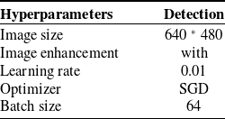
The key hyperparameters utilized in the algorithms are summarized in Table I.
Key hyperparameters.

Structure of improved YOLOv8n network: The network takes the left image from the stereo camera as its input and produces either the bounding box of the flame detection result or the flame segmentation result as its output.

3.3. Flame localization algorithm
In this section, we introduce the flame localization algorithm, which aims to accurately localize flames in image data obtained from a stereo camera system and can operate in real-time on embedded processing equipment. The algorithm utilizes the YOLOv8n network in Section 3.2 to detect and segment the flame in the left image of the stereo pair. Upon successful detection of the flame, the flame area is segmented using segmentation algorithm, and the 3D coordinates of the flame are estimated using the depth image calculated through stereo vision algorithm, which are then clustered to determine the most probable flame position. The algorithm process is shown in Figure 3.
Flame localization algorithm: The input of the algorithm is the stereo RGB image data, and the output is the three-dimensional coordinates of the flame point relative to the robot.

3.3.1. Acquisition of depth map
The camera model is as delineated by Eq. (1), wherein the initial step involves calibrating the stereoscopic camera to ascertain the intrinsic and extrinsic parameters,
 $R$
,
 $t$
, and
 $K$
. This study predominantly employs the calibration method developed by Zhang [Reference Zhang35].
 \begin{equation} \begin{bmatrix} u \\ v \\ 1 \end{bmatrix} = \mathbf{K} \begin{bmatrix} \mathbf{R} & \mathbf{t} \end{bmatrix} \begin{bmatrix} X \\ Y \\ Z \\ 1 \end{bmatrix}, \end{equation}
where
 $u$
,
 $v$
denote the coordinates on the image, and
 $K$
represents the camera’s intrinsic matrix, which includes the focal lengths (
 $f_x$
,
 $f_y$
) and the principal point (
 $c_x$
,
 $c_y$
). The principal point corresponds to the projection of the camera’s optical center onto the image plane.
 $R$
is the rotation matrix that defines the camera’s three-dimensional orientation relative to a predefined world coordinate system, and
 $t$
is the translation vector that describes the position of the camera’s optical center in the world coordinate system relative to its origin.
 $X$
,
 $Y$
,
 $Z$
represent the Cartesian coordinates of a point in three-dimensional space within the world coordinate system.
Once the camera parameters are obtained, image rectification is conducted to guarantee that the epipolar lines are coplanar and aligned with the horizontal axes of the two images. This correction simplifies the correspondence search by transforming it into a one-dimensional problem along the horizontal lines. Following rectification, disparity analysis is conducted on the stereo images. During this phase, algorithms like block matching are employed to systematically match each pixel in one image to its corresponding pixel in the other image. This process produces a disparity map that encodes the horizontal coordinate differences between corresponding points in the stereo image pair. The disparity map forms the basis for depth estimation.
By applying the principles of triangulation, as outlined in Eq. (2), and leveraging the pre-determined camera parameters, the disparity information is converted into depth measurements. This final step produces a depth map, which provides a detailed representation of the three-dimensional structure of the scene.
 \begin{equation} Z = \frac {f \times b}{d}, \end{equation}
where
 $Z$
denotes the depth value of a 3D point, calculated based on its disparity measure.
 $f$
represents the focal length of the camera’s lens, which is a known constant in a calibrated stereo camera system.
 $b$
is the baseline, defined as the distance between the optical centers of the two cameras in the stereo rig. These parameters collectively enable the conversion of disparity values into depth measurements, forming the basis for reconstructing the three-dimensional structure of the scene.
3.3.2. Flame center clustering
Upon acquiring pixel-level segmentation of the flame, it becomes imperative to ascertain the flame’s three-dimensional position relative to the firefighting robot, facilitating subsequent undertakings such as extinguishing the fire. However, conducting deep recovery on all flame points not only entails significant computational cost but also introduces a significant amount of noise that affects the accuracy of the results. Therefore, this paper employs the Mersenne Twister algorithm [Reference Matsumoto and Nishimura36] to generate high-quality pseudo-random numbers swiftly, and sampling to procure a sparse pixel set of the flame. Subsequently, the three-dimensional coordinates of the flame points are clustered through the DBSCAN [Reference Hinneburg37] algorithm based on spatial clustering.
The DBSCAN algorithm operates on the principle of spatial density for clustering. The main idea of the algorithm is to select an unvisited point from a set of spatial points, and calculate the count of points within the neighborhood defined by
 $\epsilon$
commencing from that point. If the number of points exceeds or equals the predetermined minimum number of points, denoted as mnPts, the point is classified as a core point. Consequently, every point within the domain connected to this core point is incorporated into the cluster associated with the core point. The process then proceeds to each remaining point in the domain; if the count of points within its neighborhood exceeds or equals mnPts, this point is also integrated into the core point cluster, thereby expanding the clustering region. By establishing suitable thresholds for
 $\epsilon$
and mnPts, the DBSCAN algorithm can effectively segregate different flame clusters in space and efficiently eliminate non-flame points.
Considering that the algorithm delineated in this manuscript predominantly computes flame points utilizing frontal image, it implies that the calculated flame point set is the surface points of the flame seen from the observation perspective. The calculated flame points essentially represent the centroid of the flame shell, potentially deviating from the authentic center of the flame. This deviation predominantly manifests in the form of depth disparity. To address this, the introduction of a correction factor
 $\tau$
is contemplated. The value of this correction factor can be set based on the dataset, aiming to compute the mean disparity between the calculated flame center point and the actual center point. Consequently, the ultimate result
 $P_{Center}$
can be determined as:
 \begin{equation} P_{\text{center }}=\frac {1}{N} \sum _{i=1}^N P_i+[0,0, \tau ]. \end{equation}
3.4. Dynamic flame area filtering
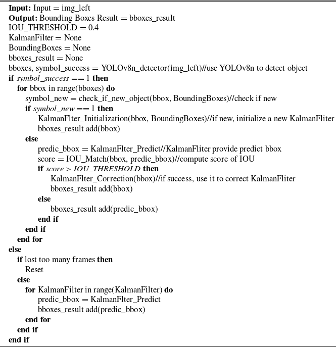
This section builds upon our previous work [Reference Ding, Pei, Yang and Chen38] to achieve flame region tracking in regular frames by combining YOLOv8n with the Kalman filter method, as shown in Algorithm 1. During the robot’s operation, mechanical vibrations or uneven terrain often induce significant image shaking or excessive motion speeds, resulting in blurred images that degrade the performance of object detection algorithms. By employing a Kalman filter to predict the positions of existing targets, short-term failures of the detection algorithm can be effectively mitigated. Additionally, leveraging the Kalman filter for target tracking enhances the overall efficiency of the algorithm, ensuring robust and accurate flame detection even under challenging conditions.
Object Tracking Algorithm

The Kalman filter is employed to maintain and predict the bounding boxes of dynamic objects. The state vector is defined as
 $x=\left [cx, cy, w, h, dx, dy, dw, dh\right ]^T$
. Here,
 $cx$
and
 $cy$
represent the horizontal and vertical coordinates of the bounding box’s center point,
 $w$
and
 $h$
denote the width and height of the bounding box, respectively,
 $dx$
,
 $dy$
,
 $dw$
, and
 $dh$
are the derivatives of these state variables, representing their rates of change over time. The state equation governing the system is:
 \begin{equation} \left \{\begin{array}{c} x_{t}=F x_{t-1}+w_{t} \\ Z_{t}=H x_{t}+v_{t} \end{array}\right ., \end{equation}
where
 $x_{t}$
,
 $x_{t-1}$
is the state estimate at
 $t$
and
 $t-1$
moment,
 $Z_{t}$
is the observation vector.
 $w_{t}$
is the process noise and
 $v_{t}$
is the measurement noise.
More specifically,
 $ F = \left [ \begin{array}{cccccccc} 1& 0& 0& 0& 1& 0& 0& 0 \\ 0& 1& 0& 0& 0& 1& 0& 0 \\ 0& 0& 1& 0& 0& 0& 1& 0 \\ 0& 0& 0& 1& 0& 0& 0& 1 \\ 0& 0& 0& 0& 1& 0& 0& 0 \\ 0& 0& 0& 0& 0& 1& 0& 0 \\ 0& 0& 0& 0& 0& 0& 1& 0 \\ 0& 0& 0& 0& 0& 0& 0& 1 \end{array} \right ]$
,
 $Z = \left [ \begin{array}{c} cx \\ cy \\ w \\ h \end{array} \right ]$
, and
 $H = \left [ \begin{array}{cccccccc} 1& 0& 0& 0& 0& 0& 0& 0 \\ 0& 1& 0& 0& 0& 0& 0& 0 \\ 0& 0& 1& 0& 0& 0& 0& 0 \\ 0& 0& 0& 1& 0& 0& 0& 0 \end{array} \right ]$
.
For each image frame containing flame bounding boxes, the extracted feature points are filtered. Points within the flame bounding boxes are classified as dynamic points. Points outside the flame bounding boxes are classified as static points. Static points are used for subsequent pose computation and loop closure detection.
4. Experiments
4.1. Dataset
4.1.1. Hardware platform and experimental setups
This study establishes both real-world and virtual reality experimental platforms for data collection and validation. In the real-world experimental platform, a firefighting robot is designed and constructed, as shown in Figure 4. The robot utilizes the Robot Operating System for motion control and is equipped with an OAK stereo camera and an Nvidia Xavier NX edge computing platform for data acquisition and processing. Additionally, the robot is fitted with a small water cannon to simulate firefighting operations. This setup provides a practical and dynamic platform for testing and validating the proposed flame detection, tracking, and SLAM algorithms under conditions that closely mimic real-world firefighting challenges.
The firefighting robot: Equipped with stereo cameras and edge processors.

The real-world environment is constructed within a
 $4 \times 4\,\text{m}$
indoor space, where a flame simulation device (Figure 5) is used to replicate realistic flame conditions. This setup provides a controlled yet dynamic environment for testing and validating the firefighting robot’s capabilities.
Flame simulation equipment:Stably generates simulated flames within a fixed width and height range.

The virtual reality experimental platform is developed using the Unity3D platform, as illustrated in Figure 6. Within this platform, a virtual factory environment spanning an area of
 $20 \times 20\,\text{m}$
is constructed. Flames can be randomly generated at different locations through commands, simulating the occurrence of fire incidents. Additionally, a virtual firefighting robot equipped with a virtual camera is integrated into the platform. This setup enables real-time data collection and recording of the robot’s pose, facilitating the validation of algorithm performance in a controlled yet dynamic virtual environment.
Virtual reality experimental platform.

4.1.2. Datasets
The dataset employed in this study is divided into two distinct parts. The first part is the flame image dataset, as depicted in Figure 7, the constituting images are real-world flame scene images sourced from the Internet and manually annotated. The second part encompasses a continuous image sequence dataset, as illustrated in Figure 8. Both of the two parts are used to train flame detection and segmentation algorithms, and the second part is used for real-time 3D localization of flame areas during the operation of firefighting robots. It contains image sequences from both indoor real-world environments and virtual reality scenes created using the Unity3D platform. The precise positions of flames and the pose of camera are documented within this dataset, thereby providing a benchmark for quantitative analysis of the algorithms.
Flame image dataset.

Continuous image sequence dataset: The upper two rows are the real-world dataset, and the lower row is the virtual reality dataset.

4.2. Flame detection and segmentation result
In this paper, YOLOv8n algorithm is used to realize flame detection and segmentation. Firstly, pre-training of detection and segmentation is performed based on the COCO dataset, respectively, to obtain the pre-training model. Then, fine-tuning is performed based on the flame detection and segmentation data set used in this paper to obtain the final model. The visualization results of the flame segmentation are exhibited in Figure 9.
The visualization of flame detection and segmentation.

Experimental results show that the algorithm can achieve flame detection and segmentation. Thus, it further effectively accomplishes the objectives of this study.
4.3. 3D flame localization experiments via Fire SLAM system
In this section, we present the flame localization experiments, which demonstrate the integration of the flame detection module with the stereo-based visual SLAM system. Specifically, the 2D flame regions detected in image frames are projected into 3D space using depth information from the stereo SLAM module and the known camera poses. This enables real-time estimation of the 3D coordinates of flames relative to the robot, which are further visualized in the global map constructed by SLAM.
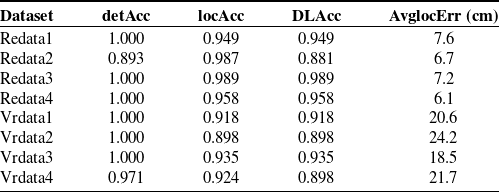
The experiments are conducted on both real and synthetic datasets with ground-truth flame positions. At the same time, we define a set of metrics to help evaluate the performance of the system. The evaluation indicators are defined as follows:
The detection accuracy, denoted as DetAcc, is defined as the ratio of correct detection in the image frames where flames are visible from the system perspective in the experimental setting. This metric is mathematically represented by the equation delineated in Eq. (5).
 \begin{equation} DetAcc = \frac {TP}{TP + FN}, \end{equation}
where TP (True Positives) represents the number of detected image frames that actually contain flame, and FN (False Negatives) represents the number of image frames where flame presence is erroneously detected or missed.
LocAcc is defined as the percentage of successful fire location when the system correctly detects the occurrence of a fire. It can be expressed by formula as shown in Eq. (6).
 \begin{equation} LocAcc = \frac {TP_{Loc}}{TP_{Det}}, \end{equation}
where
 $TP_{Loc}$
represents the number of image frames in which the flame was detected and successfully located, and
 $TP_{Det}$
represents the number of flame image frames detected.
The system integrity verification rate DLAcc was defined as the proportion of successfully detected and positioned image frames in which flames were visible from the system’s perspective in the experimental setting. It can be expressed by Eq. (7).
 \begin{equation} DLAcc = \frac {TP_{Loc}}{TP_{GT}}, \end{equation}
where
 $TP_{Loc}$
represents the number of image frames in which the flame is detected and successfully located, and
 $TP_{GT}$
represents the number of image frames in which the flame can actually be observed from the perspective of the scene.
The average positioning error AvgLocErr is defined as the average deviation between the calculated positioning coordinates and the actual flame coordinates after the fire is successfully detected in the image frame in which flames can be seen from the system’s perspective in the experiment scene. This parameter is quantified through the equation presented in (8).
 \begin{equation} AvgLocErr = \frac {1}{N} \sum _{i=1}^N |P_i - G_i|, \end{equation}
where N represents the number of image frames containing flames within the experimental scene’s field of view, wherein these flames are both successfully detected and located.
 $P_i$
represents the calculated coordinates of flame in the frame i, and
 $G_i$
represents the ground truth coordinate of flame in frame i.
The visualization results of three-dimensional flame localization are shown in the Figure 10. The quantitative statistical data are presented in Table II. These evaluations validate the effectiveness of our Fire SLAM system in accurately identifying and mapping flame positions in complex environments.
Flame localization experiments.

The visualization results of flame 3D localization: The upper row is the original image of the dataset, and the lower row is the sparse point cloud map, where the green points are the three-dimensional flame points recovered by the algorithm in this paper.

4.4. Flame position prediction under smoke occlusion
This section presents experimental validation of the Kalman filter-based flame tracking mechanism under smoke occlusion conditions. The aim is to evaluate the algorithm’s robustness when visual flame detection becomes unreliable due to smoke interference.
Since capturing large-scale real fire data with natural smoke occlusion is challenging and unsafe, we designed a controlled outdoor experiment using real flames and algorithmically simulated smoke. A sequence of images was collected during flame ignition, and semi-transparent smoke was artificially overlaid on flame regions to simulate occlusion. As illustrated in Figure 11, the upper image in Figure 11(b) shows the original flame scene, while the lower image presents the same scene with synthetic smoke.
In normal conditions (Figure 11(a)), the flame detection algorithm correctly identifies flame points (red dots). When smoke occludes the flame (Figure 11(b)), the detector fails to identify the flame regions. In such cases, the Kalman filter-based tracker continues to predict flame positions based on prior observations and motion continuity (green dots), enabling persistent localization. Once smoke clears (Figure 11(c)), detection resumes and the system switches back to using observed results (red dots).
Although the dataset size is limited due to real-world constraints, these experiments preliminarily demonstrate that the proposed algorithm can maintain tracking performance under occlusion and switch seamlessly between detection and prediction. This validates the relevance of our simulation-based experimental platform and its potential for training flame-aware models for firefighting robots. We will continue to extend this experiment with real smoke data to enhance the generalization and robustness of the proposed method.
The visualization results of flame prediction: The red points indicate the detected flame center positions, and green points represent the predicted flame center positions. Figure (a) shows the flame point detection results before the occlusion frame. Figure (b) shows the detection results of flame points without occlusion and the prediction results of flame points after artificial occlusion. Figure (c) shows the flame point detection results after the occlusion frame.

4.5. Fire SLAM experiment
In this section, we evaluate the full Fire SLAM system, which integrates flame detection with visual SLAM for enhanced pose estimation in fire environments. The image sequence dataset described in Section 4.1.2 is used to simulate a realistic firefighting scenario. In our implementation, dynamic regions containing flames are identified by the detection module and excluded from feature extraction and tracking to reduce the impact of moving fire on localization accuracy.
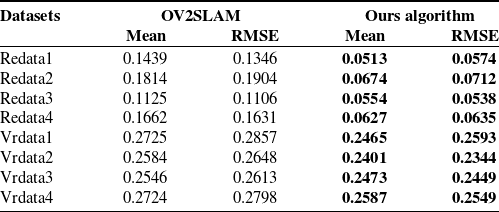
To assess the benefit of this integration, we compare our method against the baseline OV
 $^{2}$
SLAM algorithm without flame-aware filtering. The Absolute Trajectory Error (ATE) metric is used to evaluate trajectory accuracy. ATE measures the deviation between estimated and ground truth trajectories, providing a clear indication of pose estimation performance. The experimental results demonstrate a significant improvement in ATE when flame-affected regions are removed, validating the effectiveness of our flame-aware dynamic SLAM strategy.
 \begin{equation} ATE_{all}=\sqrt {\frac {1}{N}\sum _{i=1}^{N}\left \| log(T_{gt,i}^{-1},T_{esti,i})^\vee \right \| _2^2 } , \end{equation}
where
 $T_{gt,i}^{-1}$
and
 $T_{esti,i}$
denote the ground truth trajectory and the estimated trajectory to be evaluated.
The experimental results are shown in Table III. The filtering effect of the algorithm on dynamic feature points in flame regions is illustrated in Figure 12.
Absolute Trajectory Error (ATE).

The boldface values indicate the best performance among the compared methods for each evaluation metric.
The visualization of flame filtering results: the original images from the dataset are on the left. The right side displays the feature point results during the SLAM algorithm operation. The red boxes indicate the bounding box of the flame. The green points are the static feature points retained after dynamic filtering.

5. Conclusion
This paper presents a visual SLAM algorithm tailored for firefighting robots, capable of simultaneously performing accurate self-localization, real-time flame perception, and the construction of a sparse semantic map of the fire scene. By integrating flame detection, tracking, and dynamic feature filtering into the SLAM framework, the proposed system enhances the robot’s perception capabilities and improves localization accuracy in challenging fire environments. This allows the robot to assist firefighters more effectively and lays the foundation for future autonomous firefighting operations.
Additionally, the virtual reality-based experimental platform developed in this study addresses the difficulty of collecting real-world flame data. It enables the efficient and low-cost generation of diverse synthetic datasets, supporting comprehensive testing and validation of the proposed methods.
Despite the promising results, some limitations remain. In the current implementation, all feature points within the detected flame regions are conservatively treated as dynamic and excluded from pose estimation. However, in practice, some static background features may also lie within these regions. In future work, we plan to employ more refined methods for dynamic-static point classification to avoid unnecessary information loss. Furthermore, the system will be extended to identify other types of dynamic and static objects beyond flames. This would further improve pose estimation accuracy and loop closure detection, while enhancing semantic mapping and fire scene understanding, all without significantly increasing computational cost.
Author contributions
All authors contributed to the study’s conception and design. Material preparation, data collection, and analysis were performed by Tao Yang and Junjie Luo. The first draft of the manuscript was written by Tao Yang and Weili Ding. All authors commented on previous versions of the manuscript. All authors read and approved the final manuscript.
Financial support
This work was supported by the Key Projects of Hebei Natural Science Foundation F2024203051 and F2021203054, Hebei Province Higher Education Scientific Research Project CYZD202505, Performance Subsidy Funds of Hebei Province High-End Equipment Industrial Technology Research Institute (225676154H), and Major Science and Technology Support Program Project in Hebei Province 242G1802Z.
Conflicts of interest
The authors have no relevant financial or non-financial interests to disclose.
Data and code availability
The datasets and code generated during and/or analyzed during the current study are available from the corresponding author on reasonable request
Ethical approval
Not applicable.