1. Introduction
Since the first global linear instability publication appeared in the literature (Pierrehumbert & Widnall Reference Pierrehumbert and Widnall1982), it has witnessed significant advancements over the past four decades. Chomaz, Huerre & Redekopp (Reference Chomaz, Huerre and Redekopp1988) and Huerre & Monkewitz (Reference Huerre and Monkewitz1990) discussed the theory of local and global instability analysis under the assumption of parallel or weakly non-parallel flow along one spatial direction. The concepts of absolute and convective instability were introduced simultaneously to classify shear flows based on the qualitative characteristics of their dynamic behaviour. To overcome the limitations of parallel flow assumptions, the BiGlobal (Chedevergne, Casalis & Feraille Reference Chedevergne, Casalis and Feraille2006; Piot, Casalis & Rist Reference Piot, Casalis and Rist2008; Zhang & Samtaney Reference Zhang and Samtaney2016) and TriGlobal (Theofilis Reference Theofilis2003; Tammisola et al. Reference Tammisola, Giannetti, Citro and Juniper2014; Ohmichi & Yamada Reference Ohmichi and Yamada2021) stability methods have been developed. The BiGlobal and TriGlobal methods address three-dimensional flows with two and three inhomogeneous spatial directions, respectively. These stability analysis methods can be categorised into modal and non-modal approaches. Modal analysis focuses on studying the inherent modes within the flow, typically achieved by expressing perturbations as spatiotemporal modes to solve the eigenvalue problem (Natarajan & Acrivos Reference Natarajan and Acrivos1993; Marquet, Sipp & Jacquin Reference Marquet, Sipp and Jacquin2008; Citro et al. Reference Citro, Giannetti, Brandt and Luchini2015a ), or by constructing a time-independent Krylov space using the Arnoldi method (Tezuka & Suzuki Reference Tezuka and Suzuki2006; Bagheri et al. Reference Bagheri, Schlatter, Schmid and Henningson2009). Chomaz (Reference Chomaz2005) pointed out that transient algebraic growth might arise as the linear operator was not self-adjoint and led to nonlinear instability, even if all modes were linearly stable. In such cases, nonlinear non-modal analysis and direct numerical simulation (DNS) are recommended for consideration. For more detailed information on global linear stability and nonlinear non-modal stability, readers can refer to the review articles by Theofilis (Reference Theofilis2011) and Kerswell (Reference Kerswell2018), along with their associated references.
The global stability analysis provides the stability characteristics of the flow in the dimensionless parameter space, determining whether the flow is stable or unstable, while studying how variations in flow variables affect the stability properties leads to the sensitivity analysis method. Butler & Farrell (Reference Butler and Farrell1992) was the first to calculate the maximum amplification of disturbances in the parallel Blasius boundary layer using adjoint operators. Eckhardt et al. (Reference Eckhardt, Schneider, Hof and Westerweel2007) reviewed the numerical and experimental evidences for pipe flows, demonstrating that the triggering of turbulence sensitively depended on initial conditions. Giannetti & Luchini (Reference Giannetti and Luchini2007) introduced structural sensitivity analysis and identified the region of maximum coupling among the velocity components for flows past a cylinder by examining the spatial distribution of the product between the direct and adjoint modes. The discrete adjoint method enables efficient evaluation for the derivative of the eigenvalue with respect to the parameters of interest. Schneider (Reference Schneider2006) studied the derivative of a performance function with respect to shape parameters for shape optimisation, and the derivative of a posteriori error estimation with respect to node positions for adaptive mesh design in a finite element mesh. Bottaro, Corbett & Luchini (Reference Bottaro, Corbett and Luchini2003) identified the base flow modification that had the most destabilising effect on the eigenvalue in a plane Couette flow. Marquet et al. (Reference Marquet, Sipp and Jacquin2008) also studied base flow modifications and extended their research to study how the eigenvalue responded to body force variations in a two-dimensional flow around a cylinder. Saglietti et al. (Reference Saglietti, Schlatter, Monokrousos and Henningson2017) demonstrated an efficient adjoint-based optimisation technique for analysing natural convection-driven flows within a differentially heated cavity by incorporating buoyancy effects into the Navier–Stokes equations. Zheng, Pan & Ni (Reference Zheng, Pan and Ni2023) applied the analysis of base flow and body force modifications to a magnetohydrodynamic (MHD) flow past a sphere. Tchoufag, Magnaudet & Fabre (Reference Tchoufag, Magnaudet and Fabre2013) studied the stability and sensitivity of the flow around a fixed oblate spheroidal bubble across different aspect ratios, while Citro et al. (Reference Citro, Giannetti, Luchini and Auteri2015b ) focused on boundary-layer flows over a hemispherical roughness element to examine the effects of the ratio between the roughness height and the boundary layer thickness.
The focus of sensitivity analysis has developed through a more comprehensive consideration of flow mechanisms. Giannetti & Luchini (Reference Giannetti and Luchini2007) investigated the variations in the leading eigenvalue caused by a spatially localised feedback, which was generated by a perturbed force proportional to the velocity of the global direct mode (the perturbation of the base flow). They noticed that the region with significant eigenvalue variations closely resembled the area where the placement of a control cylinder suppressed vortex shedding in the experiments of Strykowski & Sreenivasan (Reference Strykowski and Sreenivasan1990). They focused on the structural sensitivity of the perturbed force. A remarkable work by Marquet et al. (Reference Marquet, Sipp and Jacquin2008) highlighted that a control cylinder also modifies the base flow on which the perturbations evolved. They proposed a general theoretical formalism to study how the modification of the body force
 $\boldsymbol{{F}}$
in the Navier–Stokes equation (1.1) altered the base flow, which in turn affected the eigenvalues. They used the base flow sensitivity function to characterise the impact on flow stability of the base flow variation, which was caused by the modification in
 $\boldsymbol{{F}}$
. They also utilised the force sensitivity function to directly investigate the influence of variations in
 $\boldsymbol{{F}}$
on the flow stability. However, in their study, the body force
 $\boldsymbol{{F}}$
is independent of the velocity, pressure or other base flow variables, similar to the gravity. When perturbations are considered, it remains a constant, meaning that the perturbed body force
 $\boldsymbol{{f}}=0$
and disappears in the eigenvalue equation. When
 $\boldsymbol{{F}}$
is coupled with the base flow variables, for instance, the Lorentz force in MHD flows, Zheng et al. (Reference Zheng, Pan and Ni2023) considered the perturbed term of the Lorentz force in the eigenvalue equation and incorporated the modification of the perturbing force into the adjoint equations to investigate the role of the magnetic field in flow stability mechanisms.
In studying the flow stability under the influence of a single force, previous works provide valuable insights into the mechanisms of flow stability and offer guidance for flow control. However, for complex systems under the influence of multiple forces, such as the simultaneous consideration of viscous, electromagnetic and buoyancy forces (Akhmedagaev et al. Reference Akhmedagaev, Zikanov, Krasnov and Schumacher2020), an existing sensitivity analysis framework based on a single force has limitations, as it can only examine the variation of one force by freezing the other forces. It is noted that these multiple forces can be coupled, with a common scenario being that various forces are all velocity-dependent, making it hard to ensure that the modification is applied solely to one specific force. Different forces represent distinct physical effects, and their intensities are characterised by the corresponding dimensionless parameters, which essentially govern the flow behaviour. In viscous flow, for instance, the Reynolds number Re plays a pivotal role in the viscosity-stratified flow instabilities, as highlighted by Govindarajan & Sahu (Reference Govindarajan and Sahu2014). In the problem considered by Akhmedagaev et al. (Reference Akhmedagaev, Zikanov, Krasnov and Schumacher2020), the flow is governed by the Rayleigh, Hartmann and Prandtl numbers
 $\textit{Ra},\textit{Ha}$
and
 ${\textit{Pr}}$
. Performing sensitivity analysis from the perspective of dimensionless parameters can be more convenient and more direct in reflecting the underlying mechanisms of the different physical factors that affect the flow stability. Thus, this paper aims to propose a generalised multiparameter linear stability and sensitivity analysis method from the perspective of sensitivity to dimensionless parameters, enabling the simultaneous analysis of the effects of multiple physical factors. In this method, different physical factors are treated as forms of forces. For the Navier–Stokes equation
 \begin{equation} \frac {\partial \boldsymbol{U}}{\partial \tau }+\boldsymbol{U}\cdot \nabla \boldsymbol{U}=-\nabla P+{\textit{Re}}^{-1}\nabla ^2\boldsymbol{U}+\boldsymbol{F}, \end{equation}
with the continuity equation
 $\nabla \cdot \boldsymbol{U}=0$
, the convection, pressure, viscosity and body force term can all be regarded as forces and abbreviated into the form as
 \begin{equation} \frac {\partial \boldsymbol{U}}{\partial \tau }=\Sigma _i \boldsymbol{F}_i. \end{equation}
Physical forces include the thermal buoyancy
 $\boldsymbol{F}=-{\textit{Gr}}{\textit{Re}}^{-2}T{\boldsymbol{e}}_g$
(Ozsunar, Baskaya & Sivrioglu Reference Ozsunar, Baskaya and Sivrioglu2001) and the electromagnetic force
 $\boldsymbol{F}=N\boldsymbol{J}\times \boldsymbol{B}$
(Priede, Aleksandrova & Molokov Reference Priede, Aleksandrova and Molokov2010), etc. Here,
 $\boldsymbol{U}, \boldsymbol{J},\boldsymbol{B}$
,
 $\tau$
,
 $P$
,
 $T$
and
 ${\boldsymbol{e}}_g$
are the velocity, current, magnetic field, time, pressure, temperature and direction of gravity, respectively. The dimensionless parameters
 ${\textit{Gr}}$
and
 $N$
represent the Grashof number and magnetic interaction parameter. These two physical forces can be conveniently considered in the same way as the viscous force, and their effects on the flow dynamics is scaled by the dimensionless parameters. Moreover, this approach allows for the incorporation of the particle’s translational and rotational motion, as inertial forces with corresponding parameters are introduced by a non-inertial reference frame related to translational or rotational motion (Mathai et al. Reference Mathai, Zhu, Sun and Lohse2018), such as the Coriolis force with the Rossby number, the ratio of inertial force to Coriolis force. Additionally, it offers feasibility in a generalised force term. For instance, through the immersed boundary method, wall boundary conditions can be represented as force distributions or source terms applied to the background grid (Fang et al. Reference Fang, Du, He, Sun, Yang, Fu and Sun2024) and then written in a force-like term with a corresponding dimensionless parameter in the momentum equation, which can be analysed within the unified theoretical framework in (1.2).
The present paper develops a generalised multiparameter global linear stability and sensitivity analysis method capable of simultaneously addressing various physical effects, such as viscosity, thermal buoyancy, electromagnetism and others. From a mathematical perspective, this method regards the eigenvalue
 $\lambda$
, representing the system’s linear stability characteristic, as a multivariate function of dimensionless parameters. For example,
 $\lambda =f({\textit{Re}},N)$
in a MHD flow. Its total differential expression is given as
 $\delta \lambda =({\partial f}/{\partial {\textit{Re}}})\delta {\textit{Re}}+ ({\partial f}/{\partial N})\delta N$
. Here,
 $\nabla ^{{\textit{glo}}}_{{\textit{Re}},N}\lambda =(({\partial f}/{\partial {\textit{Re}}}), ({\partial f}/{\partial N}))$
is defined as the global sensitivity gradient, which is the most important concept and insight in this paper. Compared with base flow sensitivity
 $\delta \lambda =({\partial \lambda }/{\partial \boldsymbol{U}})\cdot \delta \boldsymbol{U}$
or force sensitivity
 $\delta \lambda =({\partial \lambda }/{\partial \boldsymbol{F}})\cdot \delta \boldsymbol{F}$
(Marquet et al. Reference Marquet, Sipp and Jacquin2008), it considers a complete chain rule for the eigenvalue variation with respect to all relevant dimensionless parameters and accounts for the fact that both the base flow and the physical forces are dependent on these dimensionless parameters. From the perspective of dimensionless parameter sensitivity, it can be more convenient to explain the mechanisms of the flow stability variation and guide the control of flow stability. The global sensitivity gradient clarifies the functional relationship between the variation of the eigenvalue and the change in dimensionless parameters. Such a functional relationship in a multiparameter flow is established and calculated within the discrete finite element mesh in this paper. Then, applications with single, double and triple parameters are presented and several advantages of this method are discussed, such as
-
(i) facilitating fast calculation of the neutral curve;
-
(ii) assessing the competitive influence of various dimensionless parameters on flow instability;
-
(iii) providing an optimal control strategy from the perspective of system stability.
2. Formulation of the problem
2.1. Stability and sensitivity equations
For the purpose of unifying the format and facilitating derivation, the flow equations can be written in a generalised form as follows:
 \begin{equation} \frac {\partial {(\boldsymbol{\Lambda }\cdot \boldsymbol{M}})}{\partial \tau }=\boldsymbol{Q}(\boldsymbol{M},\boldsymbol{D}), \end{equation}
where
 $\boldsymbol{M}=[M_1,M_2,\ldots, M_K]$
is a vector of
 $K$
unknown field variables involved in the flow and
 $\boldsymbol{Q}=[Q_1,Q_2,\ldots, Q_K]$
is a vector function that governs the dynamics of the physical variables
 $\boldsymbol{M}$
. The dimensionless parameters appearing in
 $\boldsymbol{Q}$
are represented in a vector form as
 $\boldsymbol{D}=[D_1,D_2,\ldots, D_I]$
and the number of different dimensionless parameters is denoted as
 $I$
. Here
 $\boldsymbol{\Lambda }$
is a
 $K$
-order matrix whose elements are assigned:
 $\boldsymbol{\Lambda }_{kk}=1$
or
 $0$
depending on whether or not
 $\boldsymbol{M}_k$
evolves over time with off-diagonal elements being equal to 0. For example, in MHD flow equations (4.9)–(4.12), we have
 \begin{equation} \boldsymbol{M}=\begin{bmatrix} \boldsymbol{U} \\ P\\ \boldsymbol{J}\\ \Phi \end{bmatrix},\, \quad \boldsymbol{Q}=\begin{bmatrix} -\boldsymbol{U}\cdot \nabla \boldsymbol{U}-\nabla P+{\textit{Re}}^{-1}\nabla ^2\boldsymbol{U}+N(\boldsymbol{J}\times \boldsymbol{e}_x) \\ \nabla \cdot \boldsymbol{U}\\ \boldsymbol{J}+\nabla \Phi -\boldsymbol{U}\times \boldsymbol{e}_x\\ \nabla \cdot \boldsymbol{J} \end{bmatrix}, \end{equation}
with
 $K=4$
,
 $I=2$
and
 \begin{equation} \boldsymbol{D}=\begin{bmatrix} {\textit{Re}} \\ N \end{bmatrix},\, \quad \boldsymbol{\Lambda }=\begin{bmatrix} 1 & 0 & 0 & 0\\ 0 & 0 & 0 & 0\\ 0 & 0 & 0 & 0\\ 0 & 0 & 0 & 0 \end{bmatrix}. \end{equation}
Each component of
 $\boldsymbol{Q}$
is regarded as the sum of several forces. In this paper, we also treat terms such as
 $\nabla \cdot \boldsymbol{U}$
as a generalised force, which helps unify the notation and facilitates the derivation of conclusions.
To obtain a steady solution
 $\boldsymbol{M}$
, (2.1) with the time derivative terms omitted should be solved as
 \begin{equation} \boldsymbol{0}=\boldsymbol{Q}. \end{equation}
Fix the dimensionless parameter
 $\boldsymbol{D}$
, attach a small perturbation
 $\boldsymbol{M}^\prime$
to a steady solution
 $\boldsymbol{M}$
, the new flow
 $\boldsymbol{M}+\boldsymbol{M}^\prime$
is also a solution of (2.1). The perturbation
 $\boldsymbol{M}^\prime$
satisfies
 \begin{equation} \frac {\partial (\boldsymbol{\Lambda }\cdot \boldsymbol{M}^\prime )}{\partial \tau }=\boldsymbol{Q}^\prime, \end{equation}
where
 $\boldsymbol{Q}^\prime =\boldsymbol{Q}({\boldsymbol{M}}+{\boldsymbol{M}}^\prime, \boldsymbol{D})-\boldsymbol{Q}(\boldsymbol{M},\boldsymbol{D})=\boldsymbol{M}^\prime \cdot \nabla _{\boldsymbol{M}}\boldsymbol{Q}$
. Higher-order terms regarding
 $\boldsymbol{M}^\prime$
are neglected. Substituting the normal mode
 $\boldsymbol{M}^\prime (\boldsymbol{x},\tau )=\boldsymbol{m}(\boldsymbol{x})e^{\lambda \tau }$
of the perturbation into (2.5), the stability equation is derived as
 \begin{equation} \lambda \boldsymbol{\boldsymbol{\Lambda }}\cdot \boldsymbol{m}=\boldsymbol{q}, \end{equation}
where
 $\boldsymbol{q}=\boldsymbol{m}\cdot \nabla _{\boldsymbol{M}}\boldsymbol{Q}$
is a function of
 $\boldsymbol{M}$
,
 $\boldsymbol{m}$
and
 $\boldsymbol{D}$
. Here,
 $\boldsymbol{m}$
is the perturbed physical variables corresponding to
 $\boldsymbol{M}$
. In the MHD flow, we have
 \begin{equation} \boldsymbol{m}=\begin{bmatrix} \boldsymbol{u} \\ p\\ \boldsymbol{j}\\ \phi \end{bmatrix},\, \ \boldsymbol{q}=\begin{bmatrix} -\boldsymbol{u}\cdot \nabla \boldsymbol{U}-\boldsymbol{U}\cdot \nabla \boldsymbol{u}-\nabla p+{\textit{Re}}^{-1}\nabla ^2 \boldsymbol{u}+N(\boldsymbol{j}\times \boldsymbol{e}_x) \\ \nabla \cdot \boldsymbol{u}\\ \boldsymbol{j}+\nabla \Phi -\boldsymbol{u}\times \boldsymbol{e}_x\\ \nabla \cdot \boldsymbol{j} \end{bmatrix}. \end{equation}
The eigenvalues
 $\lambda$
are complex, with the real part
 $\lambda _r$
representing the growth rate and the imaginary part
 $\lambda _i$
representing the angular frequency. Since perturbation growth is exponential with
 $\lambda _r$
, the eigenvalue with the largest growth rate denoted as
 $\lambda _{max}$
is the leading mode and dominates the perturbation growth. As
 $\lambda _{max}$
is the main focus of this paper,
 $\lambda$
is used to represent
 $\lambda _{max}$
throughout the following text neglecting the subscript
 $max$
for simplification of notation.
If a drift in the dimensionless parameter
 $\boldsymbol{D}$
denoted as
 $\delta \boldsymbol{D}$
occurs, the variation of base flow equation (2.4)
 \begin{equation} \boldsymbol{0}=\delta \boldsymbol{Q}=\delta \boldsymbol{M}\cdot \nabla _{\boldsymbol{M}}\boldsymbol{Q}+\delta \boldsymbol{D}\cdot \nabla _{\boldsymbol{D}}\boldsymbol{Q}, \end{equation}
and the variation of stability equation
 \begin{align} &\delta \lambda \boldsymbol{\boldsymbol{\Lambda }}\cdot \boldsymbol{m}+\lambda \boldsymbol{\boldsymbol{\Lambda }}\cdot \delta \boldsymbol{m}=\delta \boldsymbol{M}\cdot \nabla _{\boldsymbol{M}}\boldsymbol{q}+\delta \boldsymbol{m}\cdot \nabla _{\boldsymbol{m}}\boldsymbol{q}+\delta \boldsymbol{D}\cdot \nabla _{\boldsymbol{D}}\boldsymbol{q}, \end{align}
are obtained. In the MHD flow, we have
 \begin{equation} \boldsymbol{\delta \boldsymbol{D}}=\begin{bmatrix} \delta {\textit{Re}} \\ \delta N\\ \end{bmatrix},\, \ \delta \boldsymbol{M}=\begin{bmatrix} \delta \boldsymbol{U}\\ \delta P\\ \delta \boldsymbol{J}\\ \delta \Phi \end{bmatrix},\, \ \delta \boldsymbol{m}=\begin{bmatrix} \delta \boldsymbol{u}\\ \delta p\\ \delta \boldsymbol{j}\\ \delta \phi \end{bmatrix}. \end{equation}
To study the sensitivity, new variables with superscript
 $^\dagger$
called the adjoint variables are introduced. In contrast, the original variables
 $\boldsymbol{M}$
are referred to as the direct variables. Here,
 $\langle \boldsymbol{a},\boldsymbol{b}\rangle =\int \boldsymbol{a}\cdot \boldsymbol{b}^*{\rm d}\Omega$
is defined as the inner product on the whole domain
 $\Omega$
of these two tensors, where the superscript
 $^*$
represents the conjugation. The adjoint variables are constructed to satisfy

For an operator
 ${\unicode{x1D4DE}}_i$
, define its adjoint operator
 ${\unicode{x1D4DE}}_i^\dagger$
so that
 \begin{equation} \langle {\unicode{x1D4DE}}_i\boldsymbol{a},\boldsymbol{b}\rangle -\langle \boldsymbol{a},{\unicode{x1D4DE}}_i^\dagger \boldsymbol{b}\rangle =\mathcal{J}_i(\boldsymbol{a},\boldsymbol{b}), \end{equation}
which is called the Lagrangian identity.
 $\mathcal{J}_i(\boldsymbol{a},\boldsymbol{b})$
is called the bilinear concomitant, determined by the difference between the two inner products and usually related to the boundary conditions. The mathematical form of the Lagrangian identity is intricately tied to the specific form of the corresponding operator (Luchini & Bottaro Reference Luchini and Bottaro2014) and varies across different problems. Substituting (2.12) into (2.11), it is simplified as follows:
 \begin{align} \delta \lambda \langle \boldsymbol{m},\boldsymbol{\Lambda }\cdot \boldsymbol{m}^{\dagger }\rangle =& \langle \delta \boldsymbol{M},\boldsymbol{M}^{\dagger }\cdot \nabla ^\dagger _{\boldsymbol{M}}\boldsymbol{Q}+\boldsymbol{m}^{\dagger }\cdot \nabla ^\dagger _{\boldsymbol{M}}\boldsymbol{q}\rangle \notag\\ &+\langle \delta \boldsymbol{m},\boldsymbol{m}^{\dagger }\cdot \nabla ^\dagger _{\boldsymbol{m}}\boldsymbol{q}-\lambda ^*\boldsymbol{\boldsymbol{\Lambda }}\cdot \boldsymbol{m}^{\dagger }\rangle \notag\\ &+\langle \delta \boldsymbol{D},\boldsymbol{M}^{\dagger }\cdot \nabla ^\dagger _{\boldsymbol{D}}\boldsymbol{Q}+\boldsymbol{m}^{\dagger }\cdot \nabla ^\dagger _{\boldsymbol{D}}\boldsymbol{q}\rangle +\Sigma _i\mathcal{J}_i. \end{align}
In the MHD flow, we have
 \begin{equation} \boldsymbol{M}^\dagger =\begin{bmatrix} \boldsymbol{U}^\dagger \\ P^\dagger \\ \boldsymbol{J}^\dagger \\ \Phi ^\dagger \end{bmatrix},\, \ \boldsymbol{m}^\dagger =\begin{bmatrix} \boldsymbol{u}^\dagger \\ p^\dagger \\ \boldsymbol{j}^\dagger \\ \phi ^\dagger \end{bmatrix}. \end{equation}
Equation (2.13) represents the total differential of the eigenvalue
 $\lambda$
with respect to the base flow
 $\boldsymbol{M}$
, perturbation
 $\boldsymbol{m}$
and dimensionless parameter
 $\boldsymbol{D}$
. We can define the local gradients of the eigenvalue with respect to these three variables as
 \begin{align} & \nabla ^{loc}_{\boldsymbol{M}}\lambda =\boldsymbol{M}^{\dagger }\cdot \nabla ^\dagger _{\boldsymbol{M}}\boldsymbol{Q}+\boldsymbol{m}^{\dagger }\cdot \nabla ^\dagger _{\boldsymbol{M}}\boldsymbol{q}, \end{align}
 \begin{align} & \,\,\,\nabla ^{loc}_{\boldsymbol{m}}\lambda =\boldsymbol{m}^{\dagger }\cdot \nabla ^\dagger _{\boldsymbol{m}}\boldsymbol{q}-\lambda ^*\boldsymbol{\boldsymbol{\Lambda }}\cdot \boldsymbol{m}^{\dagger }, \end{align}
 \begin{align} &\, \nabla ^{loc}_{\boldsymbol{D}}\lambda =\boldsymbol{M}^{\dagger }\cdot \nabla ^\dagger _{\boldsymbol{D}}\boldsymbol{Q}+\boldsymbol{m}^{\dagger }\cdot \nabla ^\dagger _{\boldsymbol{D}}\boldsymbol{q}. \end{align}
When considering the entire computational domain, the integral
 $\langle, \rangle$
should be performed, and the result of this integral is referred to as a global value, with the superscript glo to distinguish it from loc. Since we directly study the sensitivity to dimensionless parameters, it is necessary to ensure that eigenvalue only depends on the dimensionless parameter
 $\boldsymbol{D}$
. Hence, the adjoint base flow equation
 \begin{equation} \boldsymbol{M}^{\dagger }\cdot \nabla ^\dagger _{\boldsymbol{M}}\boldsymbol{Q}+\boldsymbol{m}^{\dagger }\cdot \nabla ^\dagger _{\boldsymbol{M}}\boldsymbol{q}=\boldsymbol{0}, \end{equation}
and the adjoint stability equation
 \begin{equation} \lambda ^*\boldsymbol{\boldsymbol{\Lambda }}\cdot \boldsymbol{m}^{\dagger }=\boldsymbol{m}^{\dagger }\cdot \nabla ^\dagger _{\boldsymbol{m}}\boldsymbol{q}, \end{equation}
are obtained naturally by setting the gradients of the eigenvalue with respect to the base flow and perturbation to
 $\boldsymbol{0}$
, while their boundary conditions are given by
 $\Sigma _i\mathcal{J}_i=0$
. Consequently, the variation of eigenvalue in (2.13) can be further simplified as
 \begin{equation} \delta \lambda =\langle \delta \boldsymbol{D},\boldsymbol{M}^{\dagger }\cdot \nabla ^\dagger _{\boldsymbol{D}}\boldsymbol{Q}+\boldsymbol{m}^{\dagger }\cdot \nabla ^\dagger _{\boldsymbol{D}}\boldsymbol{q}\rangle . \end{equation}
Here,
 $\langle \boldsymbol{m},\boldsymbol{\Lambda }\cdot \boldsymbol{m}^\dagger \rangle$
is a normalisation condition for the adjoint variables and it can be simply seen as equalling to unity. We define the local gradient to dimensionless parameters (2.17) as the local sensitivity gradient. The variation of dimensionless parameters
 $\delta \boldsymbol{D}$
is a constant during the integration and can be taken outside the integral as
 \begin{align} \delta \lambda &=\langle \delta \boldsymbol{D},\nabla _{\boldsymbol{D}}^{loc}\lambda \rangle \notag\\ &=\int _\Omega \delta \boldsymbol{D}\cdot \nabla _{\boldsymbol{D}}^{loc}\lambda ^*{\rm d}\Omega \notag\\ &=\int _\Omega \delta \boldsymbol{D}\cdot \mathbb{I}\cdot \nabla _{\boldsymbol{D}}^{loc}\lambda ^*{\rm d}\Omega \notag\\ &=\delta \boldsymbol{D}\cdot \langle \mathbb{I},\nabla _{\boldsymbol{D}}^{loc}\lambda \rangle \notag\\ &=\delta \boldsymbol{D}\cdot \nabla _{\boldsymbol{D}}^{{\textit{glo}}}\lambda, \end{align}
where
 $\mathbb{I}$
denotes a unit matrix. The global sensitivity gradient is defined by the integral of the local sensitivity gradient over the entire domain as
 $\nabla _{ \boldsymbol{D}}^{{\textit{glo}}}\lambda =\langle \mathbb{I},\nabla _{ \boldsymbol{D}}^{loc}\lambda \rangle$
, whose component is expressed as
 $\nabla _{ D_i}^{\textit{glo}}\lambda =\langle 1,\nabla _{ D_i}^{loc}\lambda \rangle$
. Equation (2.21) establishes the theoretical expression for the influence of dimensionless parameters on the linear stability of the flow, which illustrates how variations in different parameters compete to stabilise or destabilise the flow. It is notable that all derivations are performed in complex spaces, with the real and imaginary parts of sensitivity function corresponding to
 $\delta \lambda _r$
and
 $\delta \lambda _i$
, respectively. Bottaro et al. (Reference Bottaro, Corbett and Luchini2003); Marquet et al. (Reference Marquet, Sipp and Jacquin2008) also applied the similar adjoint-based approach in sensitivity analysis, considering the effects of variations in the base flow or forces on the eigenvalue, written as
 $\nabla^{loc}_{\boldsymbol{U}}\lambda$
or
 $\nabla^{loc}_{\boldsymbol{F}}\lambda$
. However, their work did not consider the effects of variations in dimensionless parameters. Additionally, the definition of the gradient with respect to the base flow is different: in this paper, it is defined by (2.15) and set to zero as the adjoint base flow equation (2.18); whereas in Bottaro et al. (Reference Bottaro, Corbett and Luchini2003); Marquet et al. (Reference Marquet, Sipp and Jacquin2008), it is specifically addressed and defined using present generalised operation symbols as
 $\nabla ^{loc}_{\boldsymbol{M}}\lambda =\boldsymbol{m}^{\dagger }\cdot \nabla ^\dagger _{\boldsymbol{M}}\boldsymbol{q}$
, which is not equal to zero.
2.2. Fast calculation of the neutral curve
The bisection search method shown in figure 1(
 $\textit {a}$
) is commonly used for the calculation of the neutral curve (the iso-
 $\lambda _r$
curve with
 $\lambda _r=0$
). Such a search process is usually time-consuming. However, the method proposed in this paper can facilitate the fast calculation of the neutral curve. First, the starting point
 $\boldsymbol{D}_0$
of the neutral curve can be identified using the bisection search method. Then, consider another nearby point
 $\boldsymbol{D}=\boldsymbol{D}_0+\delta \boldsymbol{D}$
on the same iso-
 $\lambda _r$
or iso-
 $\lambda _i$
curve, the real or imaginary part of eigenvalue variation between two points satisfies (2.21) with
 $\delta \lambda =0$
as
 \begin{equation} \textrm{Re}\Bigg\{\sum _i( D_i-D_{0i})\cdot \nabla _{ D_{0i}}^{\textit{glo}}\lambda \Bigg\}=0 ,\, \ \textrm{Im}\Bigg\{\sum _i( D_i-D_{0i})\cdot \nabla _{ D_{0i}}^{\textit{glo}}\lambda \Bigg\}=0, \end{equation}
which represents the tangent line (or plane) on the parameter space. Moreover, if
 $\boldsymbol{D}_0$
corresponds to a point on
 $\lambda _r=0$
, (2.22) represents a tangent line (or plane) of the neutral curve. Thus, within the linear range, the neighbouring critical points can be predicted by using this tangent equation. We call it the ‘linked predict method’, as shown in figure 1(
 $\textit {a}$
), a double-parameter space for example. Given
 $\delta D_1$
, the critical value of
 $\delta D_2$
can be calculated by the tangent formula (2.22). Adjacent critical points can be rapidly located rather than repeatedly calculating eigenvalues to find the critical parameters by using a bisection search. Therefore, the linked predict method can significantly reduce the computing time. It is noted that, in practical calculations, the eigenvalue of the predicted critical point is not strictly equal to
 $0$
, meaning that
 $\delta \lambda \neq 0$
. We use the compensation value of
 $-\delta \lambda$
rather than
 $0$
in (2.22) to avoid the accumulation of errors in the linear prediction during the iterative process.
Neutral curve calculation. (a) Comparison of two methods; (b) comparison between the neutral curve of Zheng et al. (Reference Zheng, Pan and Ni2023) (blue solid line) and present tangent direction (red arrows):
 $P_0\,{\rm is}\,N=0, {\textit{Re}}=212.7$
;
 $P_1\,{\rm is}\,N=0.5, {\textit{Re}}=285.5$
;
 $P_2\,{\rm is}\,N=1.8, {\textit{Re}}=386.3$
;
 $P_3\,{\rm is}\,N=4, {\textit{Re}}=309.3$
;
 $P_4\,{\rm is}\,N=24, {\textit{Re}}=182.7$
.

2.3. The structure of the sensitivity gradient
To obtain more specific expressions of the sensitivity gradients, the force involving the dimensionless parameter
 $ D_i$
in
 $\boldsymbol{Q}$
can be expressed as
 $\boldsymbol{{F}}_{ik}= D_i^{\alpha _k}{\unicode{x1D4D5}}_k$
where
 ${\unicode{x1D4D5}}_k$
is a function of
 $\boldsymbol{M}$
and
 $\boldsymbol{D}$
(except
 $ D_i$
) and
 $\alpha _k$
is the exponent of parameter
 $ D_i$
, for instance, the Lorentz force
 $N\boldsymbol{J}\times \boldsymbol{B}$
with
 $ D_i=N$
,
 $\alpha _k=1$
and
 ${\unicode{x1D4D5}}_k=\boldsymbol{J}\times \boldsymbol{B}$
. Similarly, the perturbed force in
 $\boldsymbol{q}$
can be expressed as
 $\boldsymbol{{f}}_{ik}= D_i^{\alpha _k}{\unicode{x1D4EF}}_k$
where
 ${\unicode{x1D4EF}}_k$
is a function of
 $\boldsymbol{M},\boldsymbol{m}$
and
 $\boldsymbol{D}$
(except
 $ D_i$
). Employ adjoint operator
 $\nabla _{ D_i}^\dagger$
upon
 $\boldsymbol{{F}}_{ik}$
and
 $\boldsymbol{{f}}_{ik}$
in (2.17) as
 \begin{align} & \nabla ^\dagger _{ D_i}\boldsymbol{F}_{ik}={\alpha _k} D_i^{{\alpha _k}-1}{\unicode{x1D4D5}}^*_k=\frac {{\alpha _k}}{ D_i} D_i^{\alpha _k}{\unicode{x1D4D5}}^*_k=\frac {{\alpha _k}}{ D_i}\boldsymbol{{F}}_{ik}^*, \end{align}
 \begin{align} &\,\, \nabla ^\dagger _{ D_i}\boldsymbol{f}_{ik}={\alpha _k} D_i^{{\alpha _k}-1}{\unicode{x1D4EF}}^*_k=\frac {{\alpha _k}}{ D_i} D_i^{\alpha _k}{\unicode{x1D4EF}}^*_k=\frac {{\alpha _k}}{ D_i}\boldsymbol{{f}}_{ik}^*. \end{align}
Equations (2.23) and (2.24) involve the appearance of conjugate symbol
 $^*$
, which results from the action of the operator
 $\nabla ^\dagger$
. Detailed derivations can be found in the Appendix A. The local sensitivity gradient with respect to
 $ D_i$
is derived by summing up all terms that contain
 $ D_i$
as
 \begin{equation} \nabla _{ D_i}^{loc}\lambda =\frac {\Sigma _k\alpha _k(\boldsymbol{{F}}_{ik}^*\cdot \boldsymbol{M}^\dagger _k+\boldsymbol{{f}}_{ik}^*\cdot \boldsymbol{m}^\dagger _k)}{ D_i}=\frac {\nabla _{ D_i\,\%}^{loc}\lambda }{ D_i}. \end{equation}
Here
 $\boldsymbol{M}^\dagger _k$
and
 $\boldsymbol{m}^\dagger _k$
are the corresponding adjoint variable multiplier, which can be determined by (2.11). Equation (2.25) takes the form of a sum of products of various forces and their corresponding adjoint variables, which is the reason why we treat each factor as an expression of force. It is applied to calculate local and global sensitivity gradients in (2.21), which considers the relationship between
 $\delta \lambda$
and
 $\delta D_i$
. Additionally, the impact of relative changes
 $\delta D_i/ D_i$
can also be studied by defining the local relative sensitivity gradient
 $\nabla _{ D_i\,\%}^{loc}\lambda$
, distinguished with the subscript
 $\,\%$
. Thus, the relationship between the eigenvalue variation and the relative change
 $\delta D_i/ D_i$
can be derived as
 \begin{equation} \delta \lambda =\sum _i\left\langle \frac {\delta D_i}{ D_i},\nabla _{ D_i\,\%}^{loc}\lambda \right\rangle =\sum _i\frac {\delta D_i}{ D_i}\langle 1,\nabla _{ D_i\,\%}^{loc}\lambda \rangle =\sum _i\frac {\delta D_i}{ D_i}\cdot \nabla _{ D_i\,\%}^{\textit{glo}}\lambda, \end{equation}
where
 $\nabla _{ D_i\,\%}^{\textit{glo}}\lambda =\langle 1,\nabla _{ D_i\,\%}^{loc}\lambda \rangle$
and its vector form
 $\nabla _{ \boldsymbol{D}\,\%}^{\textit{glo}}\lambda =\langle \mathbb{I},\nabla _{ \boldsymbol{D}\,\%}^{loc}\lambda \rangle$
is called the global relative sensitivity gradient.
2.4. Relationship with the force sensitivity function
The above is conducted from the perspective of dimensionless parameter variations. The dimensionless parameter sensitivity method proposed in this paper is consistent with the force sensitivity functions developed by previous works (Marquet et al. Reference Marquet, Sipp and Jacquin2008; Zheng et al. Reference Zheng, Pan and Ni2023). In theoretical formulations, the force sensitivity function can be derived from the dimensionless parameter sensitivity. The variation of a force
 $\boldsymbol{F}= D_i^{\alpha _k}{\unicode{x1D4D5}}_k$
and its perturbed form
 $\boldsymbol{f}= D_i^{\alpha _k}{\unicode{x1D4EF}}_k$
are denoted as
 \begin{equation} \delta \boldsymbol{F}=\delta D_i\frac {\alpha _k}{ D_i}{ D_i}^{\alpha _k}{\unicode{x1D4D5}}_k=\delta D_i\frac {\alpha _k}{ D_i}\boldsymbol{F},\, \ \delta \boldsymbol{f}=\delta D_i\frac {\alpha _k}{ D_i}{ D_i}^{\alpha _k}{\unicode{x1D4EF}}_k=\delta D_i\frac {\alpha _k}{ D_i}\boldsymbol{f}. \end{equation}
If we only consider the effect of a single force in (2.25) and omit the summation symbol that accounts for multiple forces, then substituting it into (2.21), another form can be derived to link the eigenvalue variation to the modification of a single force as
 \begin{equation} \delta \lambda =\langle \delta \boldsymbol{F},\boldsymbol{M}_k^\dagger \rangle +\langle \delta \boldsymbol{f},\boldsymbol{m}_k^\dagger \rangle . \end{equation}
A detailed derivation is provided in Appendix A. Hence, the force-sensitive function is defined as
 $\nabla _{\boldsymbol{F}}\lambda =\boldsymbol{M}^\dagger _k$
, which is consistent with Marquet et al. (Reference Marquet, Sipp and Jacquin2008) and Zheng et al. (Reference Zheng, Pan and Ni2023) that
 $\nabla _{\boldsymbol{F}}\lambda =\boldsymbol{U}^\dagger$
, since the generalised variable
 $\boldsymbol{M}_k^\dagger$
is indeed the adjoint velocity
 $\boldsymbol{U}^\dagger$
in their specific studies. Furthermore, the perturbed force-sensitive function is defined as
 $\nabla _{\boldsymbol{f}}\lambda =\boldsymbol{m}^\dagger _k$
. Equation (2.28) indicates that the present dimensionless parameter sensitivity analysis is consistent with the previous work based on the force sensitivity and emphasises the important role of the perturbed force in the perturbation dynamics. It is noted that both the base flow term and the perturbed term are of similar order of magnitude, indicating that both play a significant role in sensitivity prediction. In the problem considered by Marquet et al. (Reference Marquet, Sipp and Jacquin2008),
 $\delta \boldsymbol{f}=0$
, and therefore, they did not put emphasis on the contribution of the perturbed force variations. In the work of Zheng et al. (Reference Zheng, Pan and Ni2023),
 $\delta \boldsymbol{{f}}$
is the perturbed Lorentz force and is non-zero, but the perturbed force-sensitivity function
 $\boldsymbol{m}_k^\dagger$
and its contribution to eigenvalue variation is not considered. According to (2.25), the local sensitivity gradient can be considered as composed of two parts as
 \begin{equation} \nabla _{\boldsymbol{D}}^{loc}\lambda =\nabla _{\boldsymbol{D},b}^{loc}\lambda +\nabla _{\boldsymbol{D},p}^{loc}\lambda, \end{equation}
with the base flow part
 $\nabla _{\boldsymbol{D},b}^{loc}\lambda$
and the perturbation part
 $\nabla _{\boldsymbol{D},p}^{loc}\lambda$
expressed as
 \begin{equation} \nabla _{D_i,b}^{loc}\lambda =\frac {\Sigma _k\alpha _k\boldsymbol{{F}}_{ik}^*\cdot \boldsymbol{M}^\dagger _k}{ D_i},\, \ \nabla _{D_i,p}^{loc}\lambda =\frac {\Sigma _k\alpha _k\boldsymbol{{f}}_{ik}^*\cdot \boldsymbol{m}^\dagger _k}{ D_i}. \end{equation}
It can also be written in the relative form as
 \begin{equation} \nabla _{\boldsymbol{D}\,\%}^{loc}\lambda =\nabla _{\boldsymbol{D}\,\%,b}^{loc}\lambda +\nabla _{\boldsymbol{D}\,\%,p}^{loc}\lambda, \end{equation}
with the base flow part
 $\nabla _{\boldsymbol{D}\,\%,b}^{loc}\lambda$
and the perturbation part
 $\nabla _{\boldsymbol{D}\,\%,p}^{loc}\lambda$
expressed as
 \begin{equation} \nabla _{D_i\,\%,b}^{loc}\lambda =\Sigma _k\alpha _k\boldsymbol{{F}}_{ik}^*\cdot \boldsymbol{M}^\dagger _k,\, \ \nabla _{D_i\,\%,p}^{loc}\lambda =\Sigma _k\alpha _k\boldsymbol{{f}}_{ik}^*\cdot \boldsymbol{m}^\dagger _k. \end{equation}
The global (relative) sensitivity gradient is the integral of the local (relative) sensitivity gradient over the entire computational domain and can therefore be decomposed similarly. In the MHD flow, we have
 \begin{equation} \nabla ^{\textit{glo}}_{{\textit{Re}}\,\%}\lambda =\nabla ^{\textit{glo}}_{{\textit{Re}}\,\%,b}\lambda +\nabla ^{\textit{glo}}_{{\textit{Re}}\,\%,p}\lambda ,\, \ \nabla ^{\textit{glo}}_{{N}\,\%}\lambda =\nabla ^{\textit{glo}}_{{N}\,\%,b}\lambda +\nabla ^{\textit{glo}}_{{N}\,\%,p}\lambda, \end{equation}
for parameters Re and
 $N$
, respectively. Figure 2 shows the plots of the global relative sensitivity gradients, including both their base flow and perturbed components, along the neutral curve with
 $N$
as the horizontal coordinate. It demonstrates that the sensitivity of the perturbed component to the eigenvalue variation cannot be ignored.
The global relative sensitivity gradient, including its base flow and perturbed components, along the neutral curve in figure 1(
 $\textit {b}$
) with
 $N$
as the horizontal coordinate (a) Re relative sensitivity; (b)
 $N$
relative sensitivity.

2.5. The procedure for calculating the sensitivity gradients
Since the global sensitivity gradient is the core of the present methodology, the procedure for calculating this gradient is outlined as follows:
-
(i) solve the base flow equation (2.4) to obtain the base flow
 $\boldsymbol{M}$
;
-
(ii) using
$\boldsymbol{M}$
, solve the stability equation (2.6) to obtain the eigenvalue
$\lambda$
and the perturbed mode
$\boldsymbol{m}$
; -
(iii) with
$\boldsymbol{M}$
and
$\boldsymbol{m}$
, solve the adjoint stability equation (2.19) to obtain the conjugate eigenvalue
$\lambda ^*$
and the adjoint perturbed mode
$\boldsymbol{m}^\dagger$
; -
(iv) using
$\boldsymbol{M}$
,
$\boldsymbol{m}$
and
$\boldsymbol{m}^\dagger$
, solve the adjoint base flow equation (2.18) to obtain the adjoint base flow
$\boldsymbol{M}^\dagger$
; -
(v) once all variables
$\boldsymbol{M}$
,
$\boldsymbol{m}$
,
$\boldsymbol{m}^\dagger$
and
$\boldsymbol{M}^\dagger$
are obtained, substitute them into (2.25) to calculate the local sensitivity gradient
$\nabla _{\boldsymbol{D}}^{loc}\lambda$
as well as the local relative sensitivity gradient
$\nabla _{\boldsymbol{D\,\%}}^{loc}\lambda$
; -
(vi) finally, substitute the local sensitivity gradient into (2.21) and integrate to obtain the global sensitivity gradient
$\nabla _{\boldsymbol{D}}^{\textit{glo}}\lambda$
, and similarly for the global relative sensitivity gradient
$\nabla _{\boldsymbol{D\,\%}}^{\textit{glo}}\lambda$
; -
(vii) the fast calculation of the neutral curve, the competitive influence of various dimensionless parameters on flow instability and the optimal control strategy from the perspective of system’s stability can all be achieved based on the global sensitivity gradient.


It should be noted that the method proposed in this paper is linear and modal analysis. When the linear operator is not self-adjoint, it can lead to non-orthogonality of eigenvectors, which may result in transient algebraic growth of perturbations and potentially generate nonlinear growth (Chomaz Reference Chomaz2005; Luchini & Bottaro Reference Luchini and Bottaro2014; Kerswell Reference Kerswell2018). Although in such cases
 $\textrm{max}\{\lambda _r\}\langle 0$
is no longer a sufficient condition for stable flows, the method proposed in this paper remains applicable for sensitivity analysis of the eigenvalue variation, since the theoretical derivation does not assume orthogonality of the eigenvectors.
3. Validation
The problem of a flow past a sphere under a streamwise magnetic field is adopted for validation, which was thoroughly studied in our previous work (Zheng et al. Reference Zheng, Pan and Ni2023). The axisymmetric base flow is considered and a grid in two-dimensional cylindrical coordinates is used. The perturbation is characterised as
 \begin{equation} \boldsymbol{u}^\prime =\boldsymbol{u}(r,z)\textrm{e}^{\lambda \tau +\textrm{i}\eta \theta }, \end{equation}
where
 $r$
,
 $\theta$
and
 $z$
represent the radial, azimuthal and axial directions, respectively. Here,
 $i$
denotes the imaginary unit and
 $\eta$
represents the wavenumber of the perturbation in the azimuthal direction. The validation of grid independence and stability programmes can both be sourced from our previous work (Zheng et al. Reference Zheng, Pan and Ni2023), and thus will not be repeated here. The sensitivity analysis method and programmes are validated by comparing the results of sensitivity calculations with those of stability calculations, as shown in table 1. The specific steps are as follows:
Comparison of eigenvalue variations between sensitivity calculations by
 $\delta \lambda _{sen}=\delta Re\cdot \nabla ^{\textit{glo}}_{{\textit{Re}}}\lambda +\delta N\cdot \nabla ^{\textit{glo}}_{N}\lambda$
and stability calculations by
 $\delta \lambda _{stab}=\lambda ({\textit{Re}}+\delta {\textit{Re}},N+\delta N)-\lambda ({\textit{Re}},N)$
. The relative error is defined as
 $\textit{Err}=||\delta \lambda _{sen}-\delta \lambda _{stab}||/\delta \lambda _{stab}$
. The parameter (Re,
 $N$
) is selected along the neutral curve in figure 1(
 $\textit {b}$
).

-
(i) calculate the global sensitivity (
$\nabla ^{\textit{glo}}_{{\textit{Re}}}\lambda, \nabla ^{\textit{glo}}_{N}\lambda$
) for parameter (Re,
$N$
) to obtain the variation
$\delta \lambda _{sen}=\delta \textit{Re}\cdot \nabla ^{\textit{glo}}_{{\textit{Re}}}\lambda +\delta N\cdot \nabla ^{\textit{glo}}_{N}\lambda$
; -
(ii) calculate
$\lambda$
for parameter
$({\textit{Re}}+\delta {\textit{Re}},N+\delta N)$
to obtain the variation
$\delta \lambda _{stab}=\lambda ({\textit{Re}}+\delta {\textit{Re}},N+\delta N)-\lambda ({\textit{Re}},N)$
; -
(iii) calculate the relative error
$\textit{Err}=\|\delta \lambda _{sen}-\delta \lambda _{stab}\|/\delta \lambda _{stab}$
.


The case used for validation is in the stationary mode with
 $\lambda _i=0$
, and the imaginary part of the global sensitivity gradient is equal to zero. Table 1 shows that the sensitivity prediction aligns well with stability calculations. Even varying both Re and
 $N$
simultaneously, for example, with
 $(\delta {\textit{Re}},\delta N)=(1,0.01)$
, the relative error of the sensitivity predictions are also quite small. Moreover, the tangent line at point (
 ${\textit{Re}}_0$
,
 $N_0$
) on the neutral curve given by (2.22) can be expressed as
 \begin{equation} ({\textit{Re}}-\textit{Re}_0)\cdot \nabla _{{\textit{Re}}}^{\textit{glo}}\lambda +(N-N_0)\cdot \nabla _{N}^{\textit{glo}}\lambda =0. \end{equation}
Figure 1(
 $\textit {b}$
) shows the tangent represented by the red arrows, and the results align well with the trend of the neutral curve.
These results validate the accuracy of the sensitivity gradient in terms of both magnitude and direction. Moreover, the global sensitivity gradient leads to a method for fast calculation of the neutral curve, which we call the ‘linked predict method’. This method only calculates the stability and sensitivity for current parameters. Adjacent critical points can be determined by (3.2). However, the commonly used bisection search method as shown in figure 1(
 $\textit {a}$
) usually requires three to five times of stability calculations, and even worse if the initial setting is inappropriate. In this two-parameter example, the linked predict method is three to four times faster than the bisection search for calculating the neutral curve. The superiority of linked predict method is particularly evident in problems with even more parameters, as the bisection search time increases exponentially with the number of parameters. However, with the linked predict method, regardless of the dimensionality of the dimensionless parameter space, only one stability and sensitivity calculation is required to determine the locations of all critical points near a given critical point. Moreover, this advantage is especially pronounced in complete three-dimensional calculations, where the time required for one stability calculation is significantly large. In two-dimensional grid calculations, performing a stability calculation with
 $1.8\times10^6$
unknowns using 75 processes takes approximately 2 min in our present results. However, in three-dimensional grid calculations, performing a stability calculation with
 $75\times10^6$
unknowns using 512 processes with the modified augmented Lagrangian preconditioner takes approximately 12 hrs (Moulin, Jolivet & Marquet Reference Moulin, Jolivet and Marquet2019). Of particular note is the applicability of finite difference approximations for derivative estimation during bisection search implementations, such as
 \begin{align}& \nabla _{{\textit{Re}}}^{\textit{glo}}\lambda =\lim _{\delta {\textit{Re}}\mapsto 0}\frac {1}{\delta {\textit{Re}}}(\lambda ({\textit{Re}}+\delta {\textit{Re}},N)-\lambda ({\textit{Re}},N)), \end{align}
 \begin{align}&\, \nabla _{N}^{\textit{glo}}\lambda =\lim _{\delta { N}\mapsto 0}\frac {1}{\delta {N}}(\lambda ({\textit{Re}}, N+\delta N)-\lambda ({\textit{Re}},N)). \end{align}
For a system with
 $I$
dimensionless parameters, it necessitates
 $I+1$
stability evaluations. In contrast, present method requires one stability and one sensitivity evaluation to compute the gradient. Specifically, the stability evaluation involves solving one nonlinear equation and one eigenvalue problem while the sensitivity evaluation entails solving one linear equation and one eigenvalue problem. Consequently, the computational time for gradient calculation in this work does not exceed that of two stability evaluations. Compared with finite differences, the proposed method achieves a speedup factor of
 $(I+1)/2$
, with enhanced efficiency becoming more pronounced as the number of parameters increases. Moreover, the derivatives obtained through finite differences are merely numerical approximations, whereas the analytical form of gradients rigorously derived from the adjoint-based linear sensitivity analysis in this paper can demonstrate more profound and fundamental physical insights, which will be discussed in detail blow.
4. Discussions
The present generalised multiparameter model for linear modal stability and sensitivity analysis is applied to several application cases with different numbers of dimensionless parameters. Additionally, flow physics is directly analysed under the consideration of such general theoretical framework.
4.1. Single-parameter
We consider a classical two-dimensional open flow around a circular cylinder, with the relevant equations as
 \begin{align}& \frac {\partial \boldsymbol{U}}{\partial \tau }+\boldsymbol{U}\cdot \nabla \boldsymbol{U}=-\nabla P+{\textit{Re}}^{-1}\nabla ^2\boldsymbol{U}, \end{align}
 \begin{align}&\qquad\qquad\quad \nabla \cdot \boldsymbol{U}=0. \end{align}
A critical Reynolds number
 ${\textit{Re}}_c \approx 46.8$
exists (Marquet et al. Reference Marquet, Sipp and Jacquin2008; Govindarajan & Sahu Reference Govindarajan and Sahu2014). For
 ${\textit{Re}} \langle {\textit{Re}}_c$
, the flow is stable with a steady axisymmetric structure, while for
 ${\textit{Re}} \rangle {\textit{Re}}_c$
, the flow becomes unstable, leading to periodic vortex shedding, commonly referred to as the Kármán vortex street. By applying the method in this paper, we obtain the linear stability equation (2.6) specifically as
 \begin{equation} \lambda \begin{bmatrix} 1 & 0 \\ 0 & 0 \\ \end{bmatrix}\begin{bmatrix} \boldsymbol{u} \\ p \\ \end{bmatrix}=\begin{bmatrix} -\boldsymbol{u}\cdot \nabla \boldsymbol{U}-\boldsymbol{U}\cdot \nabla \boldsymbol{u}-\nabla p+{\textit{Re}}^{-1}\nabla ^2 \boldsymbol{u}\\ \nabla \cdot \boldsymbol{u} \end{bmatrix}, \end{equation}
the adjoint stability equation (2.19) specifically as
 \begin{equation} \lambda ^*\begin{bmatrix} 1 & 0 \\ 0 & 0 \end{bmatrix}\begin{bmatrix} \boldsymbol{u}^\dagger \\ p^\dagger \end{bmatrix}=\begin{bmatrix} \boldsymbol{U}\cdot \nabla \boldsymbol{u}^\dagger -\nabla \boldsymbol{U}\cdot \boldsymbol{u}^\dagger -\nabla p^\dagger +{\textit{Re}}^{-1}\nabla ^2 \boldsymbol{u}^\dagger \\ \nabla \cdot \boldsymbol{u}^\dagger \end{bmatrix} \end{equation}
and the adjoint base flow equation (2.18) specifically as
 \begin{equation} \begin{bmatrix} \boldsymbol{U}\cdot \nabla \boldsymbol{U}^\dagger -\nabla \boldsymbol{U}\cdot \boldsymbol{U}^\dagger +\boldsymbol{u}^*\cdot \nabla \boldsymbol{u}^\dagger -\nabla \boldsymbol{u}^*\cdot \boldsymbol{u}^\dagger -\nabla P^\dagger +{\textit{Re}}^{-1}\nabla ^2\boldsymbol{U}^\dagger \\ \nabla \cdot \boldsymbol{U}^\dagger \end{bmatrix}=\begin{bmatrix} 0 \\ 0 \end{bmatrix}. \end{equation}
The cylinder is located in the centre of a rectangular domain which its left-hand and right-hand walls are inlet and outlet boundaries coupled with the top and bottom boundaries. Their boundary conditions are determined by the bilinear concomitant
 $\Sigma _i\mathcal{J}_i=0$
. For example, boundary conditions for the adjoint stability equation (4.4) are given as:
 $\boldsymbol{u}^\dagger =\boldsymbol{0},\nabla p^\dagger \cdot \boldsymbol{n}=0$
for inlet and cylinder;
 $\nabla \boldsymbol{u}^\dagger \cdot \boldsymbol{n}=\boldsymbol{0}, p^\dagger =0$
for outlet;
 $\nabla \boldsymbol{u}^\dagger \cdot \boldsymbol{n}=\boldsymbol{0},\nabla p^\dagger \cdot \boldsymbol{n}=0$
for top and bottom. And boundary conditions for the adjoint base flow equation (4.5) are given as:
 $\boldsymbol{U}^\dagger =0,\nabla P^\dagger \cdot \boldsymbol{n}=0$
for inlet and cylinder;
 $\nabla \boldsymbol{U}^\dagger \cdot \boldsymbol{n}=0, P^\dagger =0$
for outlet;
 $\nabla \boldsymbol{U}^\dagger \cdot \boldsymbol{n}=0,\nabla P^\dagger \cdot \boldsymbol{n}=0$
for top and bottom.
The local sensitivity gradient is expressed by (2.25) as
 \begin{equation} \nabla ^{loc}_{{\textit{Re}}}\lambda =\frac {-(\boldsymbol{F}^*_v\cdot \boldsymbol{U}^\dagger +\boldsymbol{f}^*_v\cdot \boldsymbol{u}^\dagger )}{{\textit{Re}}}, \end{equation}
with
 $\boldsymbol{F}_v={\textit{Re}}^{-1}\nabla ^2\boldsymbol{U}$
and
 $\boldsymbol{f}_v={\textit{Re}}^{-1}\nabla ^2\boldsymbol{u}$
. The global sensitivity gradient is calculated by the integral of the local sensitivity gradient as
 \begin{equation} \nabla ^{\textit{glo}}_{{\textit{Re}}}\lambda =\langle 1,\nabla ^{loc}_{{\textit{Re}}}\lambda \rangle, \end{equation}
whose real and imaginary parts represent the sensitivity of the growth rate and frequency, respectively. According to (2.21), the eigenvalue variation can be expressed as
 \begin{equation} \delta \lambda _r=\delta {\textit{Re}}\cdot \textrm{Re}\{\nabla ^{\textit{glo}}_{{\textit{Re}}}\lambda \},\, \ \delta \lambda _i=\delta {\textit{Re}}\cdot \textrm{Im}\{\nabla ^{\textit{glo}}_{{\textit{Re}}}\lambda \}. \end{equation}
Figure 3 shows the perturbation growth rate
 $\lambda _r$
and the frequency
 $\lambda _i$
(
 $\textit{St} = \lambda _i/2\pi$
) depending on the Reynolds number Re. The stability calculations for both
 $\lambda _r$
and
 $\lambda _i$
(green solid lines) are in agreement with the results of Giannetti & Luchini (Reference Giannetti and Luchini2007) (black dashed lines). The red arrows represent the sensitivity gradients of growth rate and frequency, and the results of sensitivity analysis align well with stability calculations. As a result, the global sensitivity gradient effectively captures the variations in both the growth rate and frequency, which helps us understand the influence of Re on flow instability.
The eigenvalue
 $\lambda$
dependence on Re: (a) growth rate
 $\lambda _r$
; (b) Strouhal number
 $\textit{St}=\lambda _i/2\pi$
. The slopes of red arrows are determined by the real and imaginary part of the global sensitivity gradient
 $\nabla ^{\textit{glo}}_{{\textit{Re}}}\lambda$
, respectively.

4.2. Double-parameter
A three-dimensional liquid metal axisymmetric flow past a sphere with diameter
 $d=1$
with a constant streamwise magnetic field is studied for the influence of Re and
 $N$
on the flow instability. It was thoroughly investigated in our previous work (Zheng et al. Reference Zheng, Pan and Ni2023). Here, we use it as a double-parameter application example of the present method. The flow equations can be written in a specific form as
 \begin{align}& \frac {\partial \boldsymbol{U}}{\partial \tau }=-\boldsymbol{U}\cdot \nabla \boldsymbol{U}-\nabla P+\boldsymbol{F}_v+\boldsymbol{F}_L, \end{align}
 \begin{align}&\qquad\qquad\quad 0=\nabla \cdot \boldsymbol{U}, \end{align}
 \begin{align}&\qquad\quad 0=\boldsymbol{J}+\nabla \Phi -\boldsymbol{U}\times \boldsymbol{e}_x, \end{align}
 \begin{align}&\qquad\qquad\quad 0=\nabla \cdot \boldsymbol{J}, \end{align}
where
 $\Phi$
and
 $\boldsymbol{e}_x$
represent the electric potential and the streamwise direction.
 $\boldsymbol{F}_v={\textit{Re}}^{-1}\nabla ^2 \boldsymbol{U}$
is the viscous force and
 $\boldsymbol{F}_L=N(\boldsymbol{J}\times \boldsymbol{e}_x)$
is the Lorentz force. The specific forms of the stability equation (2.6), adjoint stability equation (2.19) and adjoint base flow equation (2.18), as well as their boundary conditions can all be found in detail in Appendix A. The local sensitivity gradients are given by (2.25) as
 \begin{equation} \nabla _{{\textit{Re}}}^{loc}\lambda =-\frac {\boldsymbol{\boldsymbol{F}}_v^*\cdot \boldsymbol{U}^\dagger +\boldsymbol{f}_{v}^*\cdot \boldsymbol{u}^\dagger }{{\textit{Re}}},\, \ \nabla _{N}^{loc}\lambda =\frac {\boldsymbol{\boldsymbol{F}}_L^*\cdot \boldsymbol{U}^\dagger +\boldsymbol{f}_{L}^*\cdot \boldsymbol{u}^\dagger }{N}, \end{equation}
where
 $\boldsymbol{f}_v={\textit{Re}}^{-1}\nabla ^2 \boldsymbol{u}$
and
 $\boldsymbol{f}_L=N(\boldsymbol{j}\times \boldsymbol{e}_x)$
represent the perturbed viscous force and the perturbed Lorentz force, respectively. The global sensitivity gradients are given by
 \begin{equation} \nabla _{{\textit{Re}}}^{\textit{glo}}\lambda =\langle 1,\nabla _{{\textit{Re}}}^{\textit{glo}}\lambda \rangle ,\, \ \nabla _{N}^{\textit{glo}}\lambda =\langle 1,\nabla _{N}^{loc}\lambda \rangle . \end{equation}
The variation of eigenvalue can be written as
 \begin{equation} \delta \lambda =\delta {\textit{Re}}\cdot \nabla _{{\textit{Re}}}^{\textit{glo}}\lambda +\delta N\cdot \nabla _{N}^{\textit{glo}}\lambda . \end{equation}
The linear stability of the system is governed by its maximum
 $\lambda _r$
, with each
 $\lambda _r$
representing a distinct stability state level. The imaginary part
 $\lambda _i = 0$
or
 $\lambda _i \neq 0$
represents the stationary or oscillating growth pattern of the perturbation. If the real part
 $\lambda _r\rangle 0$
, the perturbation will grow in energy and the flow is unstable. If
 $\lambda _r\langle 0$
, the perturbation decays and the flow is stable. If
 $\lambda _r=0$
, the flow is in a critical state and the corresponding contour is the neutral curve. The larger the eigenvalue
 $\lambda _r$
, the more unstable the flow. Within the parameter space defined by
 $\{{\textit{Re}}, N\}$
, every point corresponds to a specific
 $\lambda$
. The range of parameters studied here is selected to ensure that the bifurcation is regular with
 $\lambda _i=0$
, resulting in
 $\lambda =\lambda _r$
for simplicity. Points with identical
 $\lambda _r$
can be connected to form iso-
 $\lambda _r$
curves. Along these curves,
 $\lambda _r$
remains constant, reflecting a consistent stability level. Conversely, traversing normal to these curves, determined by the real part of global sensitivity gradient, induces the maximum change rate of
 $\lambda _r$
. The imaginary part of the global sensitivity gradient is equal to zero, which is consistent with the fact that
 $\lambda _i=0$
at all parameter points within the range of this study.
Iso-
 $\lambda _r$
curves (solid lines) and global sensitivity gradient direction (red and black solid arrows). Here SS, CS, US I, US II denote states of stability: stable; critical; unstable I; more unstable II, respectively.

Figure 4 shows four contour lines with an interval of
 $\delta \lambda _r=0.002$
, where the values of
 $\lambda _r$
are
 $-0.002$
, 0, 0.002, and 0.004, representing a stable state (SS), a critical state (CS), an unstable state I (US I) and a more unstable state II (US II), respectively. The critical state (CS), i.e. the neutral curve, divides the parameter plane of
 ${\textit{Re}}\mbox{--}N$
into two regions: the stable region on the left-hand side and the unstable region on the right-hand side. When the parameter pair (
 ${\textit{Re}}, N$
) is located to the left of the neutral curve, perturbations decay and the vortex structure remains axisymmetric; when (
 ${\textit{Re}}, N$
) is located to the right of the neutral curve, perturbations grow, the axisymmetric structure becomes unstable and the flow transitions from an axisymmetric structure to a planar symmetric structure. The red solid arrows pointing from CS to US I and the black solid arrows pointing from US I to US II represent the direction of the real part of the global sensitivity gradient
 $\textrm{Re}\{\nabla ^{\textit{glo}}_{{\textit{Re}},N}\lambda \}$
at local parameter points, while its magnitude signifies the distance the parameter point
 $({\textit{Re}},N)$
needs to traverse along this direction to achieve
 $\delta \lambda _r=0.002$
, which is determined by (4.15). The red arrows pointing from CS (
 $\lambda _r=0$
) towards SS (
 $\lambda _r=-0.002$
) convey the same meaning, but their directions are opposite to
 $\textrm{Re}\{\nabla ^{\textit{glo}}_{{\textit{Re}},N}\lambda \}$
since they represent the prediction of
 $\delta \lambda _r\langle 0$
. In the neighbourhood of the critical state, the unstable state II can be quickly predicted by CS
 $\rightarrow$
US I
 $\rightarrow$
US II based on the properties of the global sensitivity gradient, without calculating its isocurve completely. To visually emphasise the orthogonality between
 $\textrm{Re}\{\nabla ^{\textit{glo}}_{{\textit{Re}},N}\lambda \}$
and iso-
 $\lambda _r$
curves, and to ensure that the gradients reflect the influence of Re and
 $N$
on flow stability intuitively, the scaling of the axes in figure 4 is set to be equal.
Based on the observations in figure 4, the interaction between Re and
 $N$
can be delineated into four regions. Within the domain characterised by weak magnetic field intensities, as shown in zoom 2, the direction of parameters’ variation that makes the system more unstable is almost vertically downwards (from red line to cyan). The magnetic field emerges as the dominant factor governing the flow instability. An increase of
 $N$
stabilises the flow. However, at moderate magnitudes of the magnetic field as shown in zoom 1, the direction of parameter change inducing flow instability shifts upwards. The magnetic field still dominates the flow stability, but the increase in
 $N$
shows a destabilising effect rather than stabilisation. As
 $N$
continues to increase in the leftmost segment of figure 4, the direction that makes the flow more unstable gradually turns clockwise from almost vertically downwards in zoom1 to almost horizontal left at
 $N=40$
. Along iso-
 $\lambda _r$
curves, the magnetic sensitivity gradually decreases to zero while Re sensitivity gradually increases, which indicates that the magnetic field diminishes its impact on instability and viscous effect becomes increasingly significant and dominant. Using DNS, Zheng et al. (Reference Zheng, Pan and Ni2023) also found that magnetic field exhibits the dual effect of stabilisation and destabilisation through the utilisation of Lorentz force sensitivity and perturbation energy analysis. However, Zheng et al. (Reference Zheng, Pan and Ni2023) focused solely on the sensitivity of Lorentz force by the parameter
 $N$
and did not consider the competition of parameter Re with it. The method present in this paper can simultaneously consider the influence of multiple parameters on flow stability, allowing for a direct and intuitive representation of their competitive relationship. Figure 5 shows the distribution of the local sensitivity gradient with respect to Re and
 $N$
. Figure 5(ai–ei) show that the influence of Re on stability is primarily observed upstream of the separation bubble. At weak magnetic fields, there is also some contribution near the shear layer. As
 $N$
increases, this contribution gradually weakens, and the region upstream of the separation bubble, where the primary contributions to the eigenvalue variation come from, becomes progressively confined to the surface of the sphere. Figure 5(aii–eii) show that, when
 $N\leqslant 1.8$
, the magnetic field exhibits a destabilising effect within the separation bubble, while its stabilising effect is mainly observed in the shear layer downstream of the separation point. As
 $N$
increases beyond 1.8, the magnetic field further compresses and elongates the separation bubble. On one hand, the destabilising effect within the separation bubble becomes more pronounced; on the other hand, the stabilising effect on the shear layer diminishes. As a result, when
 $N\gt 1.8$
, the magnetic field exhibits an overall destabilising effect.
The distribution of the local sensitivity gradient on the neutral curve, (i)
 $\nabla ^{loc}_{{\textit{Re}}}\lambda$
and (ii)
 $\nabla ^{loc}_{N}\lambda$
: (
 $\textit {a}$
)
 $P_0\,{\rm is}\,N=0, {\textit{Re}}=212.7$
; (
 $\textit {b}$
)
 $P_1\,{\rm is}\,N=0.5, {\textit{Re}}=285.5$
; (
 $\textit {c}$
)
 $P_2\,{\rm is}\,N=1.8, {\textit{Re}}=386.3$
; (
 $\textit {d}$
)
 $P_3\,{\rm is}\,N=4,$
 ${\textit{Re}}=309.3$
; (
 $\textit {e}$
)
 $P_4\,{\rm is}\,N=24, {\textit{Re}}=182.7$
. The red solid line represents the outline of the separation bubble.

A transition from stabilising to destabilising effect of the magnetic field is shown in zoom 3. The curvature changes dramatically near the extremum point
 $({\textit{Re}}, N) = (386.3, 1.8)$
. Such a sharp variation observed in the neutral curve arises from the steep gradients of the eigenvalue function
 $\lambda _r({\textit{Re}}, N)$
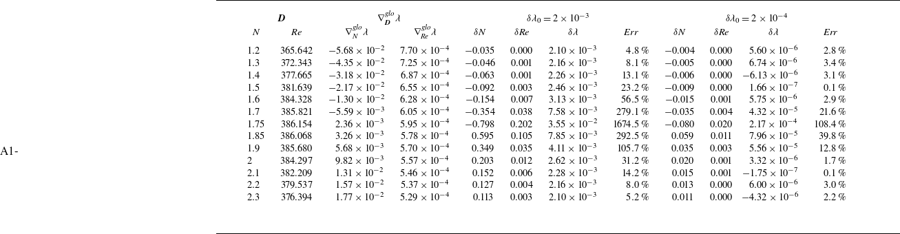
, and serves as a sign of strong nonlinearity. The span of
 $\delta \lambda _r=0.002$
has exceeded the linear range. If linear prediction is still being utilised, the span needs to be reduced to a smaller value, such as
 $\delta \lambda _r=2\times 10^{-4}$
. The sensitivity calculations along the neutral curve in the vicinity of the extremum point are presented in table 2. With an expected eigenvalue variation
 $\delta \lambda _0$
, the dimensionless parameter variations are determined by
 \begin{equation} (\delta {\textit{Re}},\delta N)=\frac {\delta \lambda _0}{(\nabla _{{\textit{Re}}}^{\textit{glo}}\lambda )^2+(\nabla _{N}^{\textit{glo}}\lambda )^2}(\nabla _{{\textit{Re}}}^{\textit{glo}}\lambda, \nabla _{N}^{\textit{glo}}\lambda ). \end{equation}
The exact eigenvalue variation is given by
 $\delta \lambda =\lambda ({\textit{Re}}+\delta {\textit{Re}},N+\delta N)-\lambda ({\textit{Re}},N)$
and the relative error is defined as
 $\textit{Err}=||\delta \lambda -\delta \lambda _0||/\delta \lambda _0$
. Two cases for
 $\delta \lambda _0= 2 \times 10^{-3}$
and
 $\delta \lambda _0 = 2 \times 10^{-4}$
are considered. Figure 6(
 $\textit {a}$
) presents a graphical representation of the sensitivity prediction errors from table 2. When
 $\delta \lambda _0=2\times 10^{-3}$
, linear prediction is relatively effective in regions far from the extremum
 $N=1.8$
, such as
 $N=1.2$
and
 $N=2.3$
. However, near the extremum, such as
 $N=1.7$
,
 $N=1.75$
and
 $N=1.85$
, linear prediction for
 $\delta \lambda _0=2\times 10^{-3}$
completely fails. If
 $\delta \lambda _0$
is reduced to
 $2\times 10^{-4}$
, the accuracy of linear prediction near the extremum improves with smaller relative errors, and further reduction of
 $\delta \lambda _0$
will yield better linear prediction. It shows that the effective range of linear prediction near the extremum is much smaller. In other words, nonlinearity is significant in this region. Boujo (Reference Boujo2021) proposed a second-order sensitivity analysis method that improved the predictions of classical linear sensitivity analysis, which could be potentially applied to the present work to enhance sensitivity predictions in the nonlinear region. Figure 6(
 $\textit {b}$
) shows the global sensitivity gradients with respect to Re and
 $N$
. Within this parameter range, the global sensitivity to Re is minimal and remains approximately constant, primarily exhibiting sensitivity to
 $N$
. The variation in
 $N$
has a more significant impact on flow instability than that in Re, which means that the magnetic field is the main reason for this phenomenon.
Errors in the predicted eigenvalue variations along the neutral curve in figure 4 near the extremum point
 $({\textit{Re}},N)=(386.3,1.8)$
. The relative error is defined as
 $\textit{Err}=||\delta \lambda -\delta \lambda _0||/\delta \lambda _0$
.

The test for sensitivity calculations on the neutral curve in figure 4 near the extremum point
 $({\textit{Re}}, N) = (386.3, 1.8)$
. (
 $\textit {a}$
) The global sensitivity of Re and
 $N$
; (
 $\textit {b}$
) the relative error for
 $\delta \lambda _0=2\times 10^{-3}$
and
 $\delta \lambda _0=2\times 10^{-4}$
.

Figure 4 also provides insights into optimising parameter control strategies with a focus on stability. In practical engineering applications, the task of stabilising an unstable system is often encountered. For example in aircraft engines, flutter stemming from the progressive destabilisation of initial blade vibrations, stands out as a critical failure factor (Yuan & Zhang Reference Yuan and Zhang2023). Nastro et al. (Reference Nastro, Robinet, Loiseau, Passaggia and Mazellier2023) studied low-Reynolds-number flows around NACA 4412 swept wings from the perspective of force sensitivity. They pointed out that a spanwise-homogeneous force suppressed the Hopf bifurcation and stabilised the entire branch of von Kármán modes. In the limit of small amplitudes, passive control via spanwise-wavy forcing produced a stabilising effect similar to that of spanwise-homogeneous control. Khalak (Reference Khalak2002) noted that control can be assessed through a set of similarity parameters like combined mass-damping parameter and compressible reduced frequency parameter. The properties of the global sensitivity gradient provide valuable insights. By controlling the relevant parameters to change along a specific path, the system can transition rapidly, monotonically and robustly from an unstable to a stable state, effectively preventing instability issues such as flutter. To illustrate the control process in detail, the iso-
 $\lambda _r$
curves in figure 4 are used as a demonstration. Assume the system is initially in an unstable state II at point
 $\textrm {U}_2$
and needs to be controlled to a stable state at point
 $\textrm {S}_2$
. There are many paths, such as the ordinary path I or path II (green dashed line), to transition to a stable state. Path I encounters two intersections with the blue contour (
 $\lambda _r=0.004$
). Along this path, the eigenvalue first increases and then decreases, exacerbating the instability before reaching the target parameters. If path II is chosen, the eigenvalue continues to decrease after reaching the same stable state as target. Although it looks better than path I, problem still exits that the system reaches an excessively stable state before gradually destabilising towards the desired state. Along these paths, the eigenvalue changes non-monotonically, which may lead to fluctuations in stability level of the system. Such fluctuations may cause damage to the system as parameters change. However, based on the global sensitivity gradient, the system can be controlled to a desired stable state along the path
 $\textrm {U}_2\rightarrow U_1\rightarrow C\rightarrow S_1$
, during which the system stabilises monotonically and steeply. Then, by varying parameters along the iso-
 $\lambda _r$
curve
 $\textrm {S}_1\rightarrow S_2$
, the system reaches the final desired state while maintaining its stability level. Therefore, an optimal path is established as
 $\textrm {U}_2\rightarrow U_1\rightarrow C\rightarrow S_1\rightarrow S_2$
(magenta dashed line), ensuring the system’s stability state changes monotonically, steeply and robustly towards the target. In summary, to move the parameter pair from
 $\textrm {U}_2$
to
 $\textrm {S}_1$
, multiple iterations are required, using (4.16) to determine the parameter variation
 $\delta {\textit{Re}}$
and
 $\delta N$
of each iteration; multiple iterations are also required for the movement
 $\textrm {S}_1\rightarrow \textrm {S}_2$
along the isoeigenvalue curve, using (3.2) with an additional preset value like
 $\delta N=0.01$
or other suitable conditions to uniquely determine the parameter variation pair (
 $\delta {\textit{Re}},\delta N)$
of each iteration. Therefore, in numerical experiments by DNS, dimensionless parameters can be directly modified within the programme. In practical experiments, based on the expressions of
 ${\textit{Re}}=U_\infty d/\nu$
and
 $N=\sigma {\rm d}B^2/\rho U_\infty$
, variations in Re can be achieved by adjusting the free stream velocity
 $U_\infty$
, while variations in
 $N$
can be realised by altering the magnetic field strength
 $B$
. Additionally, the desired dimensionless parameter variations can also be achieved by replacing the fluid material to appropriately adjust properties, such as the density
 $\rho$
and kinetic viscosity
 $\nu$
.
The variation of recirculation length as parameters change along three paths from the start point
 $\textrm {U}_2$
to the target point
 $\textrm {S}_2$
. The recirculation length is measured by the zero velocity point in the rear of the sphere.

To evaluate the effectiveness of this control strategy, DNS is conducted with a second-order accurate, consistent and conservative numerical scheme. Detailed information regarding the numerical method can be found in Ni et al. (Reference Ni, Munipalli, Huang, Morley and Abdou2007) and Pan et al. (Reference Pan, Ni and Zhang2018a
). In the flow past a sphere without a magnetic field, as Re increases across the first regular bifurcation
 ${\textit{Re}}_{c1}\approx 212$
, the flow stability decreases and transitions from an axisymmetric state to a plane-symmetric state. Furthermore, the recirculation length increases accordingly with enlarging the Reynolds number (Bagchi & Balachandar Reference Bagchi and Balachandar2002; Clift, Grace & Weber Reference Clift, Grace and Weber2005). The recirculation length may approximately reflect the stability of the flow, and the longer recirculation length tends to be associated with heightened instability in the flow. Hence, the symmetry and the recirculation length are employed here as indicators of the flow instability for DNS, where the plane-symmetry or the longer recirculation length denote a more unstable state. With these two indicators, figure 7 can show the change of system instability by DNS as the dimensionless parameter point moves along three different paths from the start point
 $\textrm {U}_2$
to the target point
 $\textrm {S}_2$
. The horizontal axis, labelled as
 $l$
, represents the proportion of the parameter point’s travelling distance to the overall length of each respective path. Along path I, although the recirculation length is decreasing, it remains plane-symmetric over an extended range, failing to efficiently transition to an axisymmetric state. Along path II, the recirculation length first decreases and then increases. This non-monotonicity is consistent with the non-monotonic variation in eigenvalues. Along the optimal path, the recirculation length decreases monotonically, which also transitions most rapidly from plane-symmetry to axisymmetry compared with the path II. Furthermore, figure 8 shows the skin friction lines on the sphere surface, which can clearly show flow traces in the rear of the sphere and help us analyse the wake structure (Pan et al. Reference Pan, Zhang and Ni2018b
). The skin friction lines illustrate the axisymmetric state of
 $\mathrm{S}_1(175.2,25.86)$
, the planar symmetric state of
 $\mathrm{U}_1(185.1,29.76)$
and the planar symmetric state of
 $\mathrm{U}_2(190,31)$
that deviates more from axisymmetry in the parameter space
 $\textit{Re}\mbox{--}$
N. These DNS results are consistent with the analysis from the perspective of the optimal control strategy.
Skin friction lines on the sphere surface: (a)
 $\textrm {U}_2$
is
 ${\textit{Re}}=190$
,
 $N=31$
, plane-symmetric; (b)
 $\textrm {U}_1$
is
 ${\textit{Re}}=185.1$
,
 $N= 29.76$
, plane-symmetric; (c)
 $\textrm {S}_1$
is
 ${\textit{Re}}=175.2$
,
 $N= 25.86$
, axisymmetric. These three plots correspond to the first three points from left to right on the optimal path in figure 7.

Global relative sensitivity gradient along the neutral curve versus (
 $\textit {a}$
)
 $N$
; (
 $\textit {b}$
) Re.

Figures 9(
 $\textit {a}$
) and 9(
 $\textit {b}$
), respectively, show the projection onto Re axis and
 $N$
axis of the global relative sensitive gradient along the neutral curve. Figure 9(
 $\textit {a}$
) reflects the dual effects of magnetic field stabilisation (
 $\mathrm{P}_0$
to
 $\mathrm{P}_2$
with negative gradients) and destabilisation (
 $\mathrm{P}_2$
to
 $\mathrm{P}_4$
with positive gradients) corresponding to figure 1(b). The relative sensitivity to the magnetic field drops to nearly zero when
 $N$
is large. Additionally, the increased field continuously weakens the relative sensitivity of Re. Figure 9(
 $\textit {b}$
) clearly reflects that Re in some interval corresponds to two different critical
 $N$
. Zheng et al. (Reference Zheng, Pan and Ni2023) concluded that the magnetic field stabilises the flow through Joule dissipation while simultaneously destabilising it by exacerbating the shear instability; the former dominates in small
 $N$
while the latter becomes dominant in large
 $N$
. Changing Re can obviously alter the recirculation structure of flows past a sphere in the absence of magnetic field. However, the strong magnetic field preserves the fundamental shear structure of the flow, rendering it nearly invariant. On the contrary, the shear structure under small
 $N$
is unlocked and noticeably affected by Re (Zheng et al. Reference Zheng, Pan and Ni2023). Such a conclusion is supported by the results depicted in figure 9(
 $\textit {b}$
) that the relative sensitivity to Re at small
 $N$
is much greater than that at large
 $N$
at the same Re.
4.3. Triple-parameter
The flow configuration for the MHD mixed convection case.

The problem of MHD mixed convection in a two-dimensional periodic channel is considered on the parameter space
 ${\textit{Re}}\!-\!\textit{Ha}\!-\!{\textit{Gr}}$
, where
 $\textit{Ha}$
is the Hartmann number. The flow configuration for this problem is shown in figure 10, with the periodic velocity boundary condition
 $U_{in}=U_{out}$
and the periodic temperature boundary condition
 $T_{in}=T_{out}$
. The upper and lower boundaries are no-slip wall boundaries with a temperature difference
 $\Delta T=T_{low}-T_{up}\gt 0$
. The magnetic field
 $\boldsymbol{B}_0$
is constant and perpendicular to the flow direction. The entire computational domain is
 $x: [-0.5, 0.5]$
and
 $y: [-0.1, 0.1]$
. The flow satisfies
 \begin{align}& \frac {\partial \boldsymbol{U}}{\partial \tau }=-\boldsymbol{U}\cdot \nabla \boldsymbol{U}-\nabla (P+\hat {P})+{\textit{Re}}^{-1}\nabla ^2\boldsymbol{U}+{{\textit{Gr}}}{\textit{Re}}^{-2}T\boldsymbol{e}_y-{\textit{Ha}}{\textit{Re}}^{-1}\boldsymbol{U}, \end{align}
 \begin{align}&\qquad\qquad\qquad\qquad\qquad\qquad 0=\nabla \cdot \boldsymbol{U}, \end{align}
 \begin{align}&\qquad\qquad\qquad\qquad \frac {\partial T}{\partial \tau }=-\boldsymbol{U}\cdot \nabla T+{\textit{Re}}^{-1}{{\textit{Pr}}}^{-1}\nabla ^2T, \end{align}
where
 ${\textit{Re}}=\bar {U}_{in}H/\nu$
is the Reynolds number defined by the average inlet velocity
 $\bar {U}_{in}$
when the flow is fully developed and reaches a steady state,
 ${\textit{Gr}}=g\beta \Delta TH^3/\nu ^2$
is the Grashof number,
 $\textit{Ha}=B_0H\sqrt {\frac {\sigma }{\nu \rho }}$
is the Hartmann number and
 ${\textit{Pr}}=\nu /\alpha$
is the Prandtl number. Here
 $\nabla \hat {P}$
is a constant pressure gradient term that drives the flow to the corresponding Re state in a periodic channel. Here,
 $H, g, \beta, \nu, \alpha, \sigma, \rho, B_0$
represent channel height, gravitational acceleration, coefficient of volume expansion, kinematic viscosity, thermal diffusivity, electrical conductivity, density and magnitude of magnetic induction, respectively. By applying the method presented in this paper, we obtain the linear stability equation (2.6) specifically as
 \begin{equation} \lambda \!\begin{bmatrix} 1 \!& 0 \!& 0\\ 0 \!& 0 \!& 0\\ 0 \!& 0 \!& 1 \end{bmatrix}\!\begin{bmatrix} \boldsymbol{u} \\ p \\ t \end{bmatrix}\!=\!\begin{bmatrix} \!-\boldsymbol{u}\cdot \nabla \boldsymbol{U}-\boldsymbol{U}\cdot \nabla \boldsymbol{u}-\nabla p+{\textit{Re}}^{-1}\nabla ^2 \boldsymbol{u}+{\textit{Gr}}{\textit{Re}}^{-2}t\boldsymbol{e}_y-\textit{Ha}{\textit{Re}}^{-1}\boldsymbol{u}\\ \nabla \cdot \boldsymbol{u} \\ -\boldsymbol{U}\cdot \nabla t-\boldsymbol{u}\cdot \nabla T+{\textit{Re}}^{-1}{{\textit{Pr}}}^{-}\nabla ^2 t \!\end{bmatrix}\!. \end{equation}
It should be distinguished that
 $\tau$
represents time and
 $t$
represents temperature perturbation. The adjoint stability equation (2.19) is specifically written as
 \begin{align} &\lambda ^*\begin{bmatrix} 1 & 0 & 0\\ 0 & 0 & 0\\ 0 & 0 & 1 \end{bmatrix}\begin{bmatrix} \boldsymbol{u}^\dagger \\ p^\dagger \\ t^\dagger \end{bmatrix}\notag\\&\quad =\begin{bmatrix} \boldsymbol{U}\cdot \nabla \boldsymbol{u}^\dagger -\nabla \boldsymbol{U}\cdot \boldsymbol{u}^\dagger -\nabla p^\dagger +{\textit{Re}}^{-1}\nabla ^2 \boldsymbol{u}^\dagger -\nabla T\cdot t^\dagger -\textit{Ha}{\textit{Re}}^{-1}\boldsymbol{u}^\dagger \\ \nabla \cdot \boldsymbol{u}^\dagger \\ \boldsymbol{U}\cdot \nabla t^\dagger +{\textit{Gr}}{\textit{Re}}^{-2}\boldsymbol{u}^\dagger \cdot \boldsymbol{e}_y+{\textit{Re}}^{-1}{{\textit{Pr}}}^{-1}\nabla ^2 t^\dagger \end{bmatrix}, \end{align}
and the adjoint base flow equation (2.18) is specifically written as
 \begin{equation} \begin{bmatrix} \boldsymbol{U}\cdot \nabla \boldsymbol{U}^\dagger -\nabla \boldsymbol{U}\cdot \boldsymbol{U}^\dagger +\boldsymbol{u}^*\cdot \nabla \boldsymbol{u}^\dagger -\nabla \boldsymbol{u}^*\cdot \boldsymbol{u}^\dagger -\nabla P^\dagger -\nabla T\cdot T^\dagger -\nabla t^*\cdot t^\dagger\\ +{\textit{Re}}^{-1}\nabla ^2U^\dagger -\textit{Ha}{\textit{Re}}^{-1}\boldsymbol{U}^\dagger \\ \nabla \cdot \boldsymbol{U}^\dagger \\ \boldsymbol{U}\cdot \nabla T^\dagger +\boldsymbol{u}^*\cdot \nabla t^\dagger +{\textit{Gr}}{\textit{Re}}^{-2}\boldsymbol{U}^\dagger \cdot \boldsymbol{e}_y+{\textit{Re}}^{-1}{{\textit{Pr}}}^{-1}\nabla ^2 T^\dagger \end{bmatrix}=\begin{bmatrix} 0 \\ 0 \end{bmatrix}. \end{equation}
Similarly, boundary conditions for the adjoint equations are given by
 $\Sigma _i\mathcal{J}_i=0$
as
 $\boldsymbol{u}^\dagger _{in}=\boldsymbol{u}^\dagger _{out},t^\dagger _{in}=t^\dagger _{out},\boldsymbol{u}^\dagger _{up}=\boldsymbol{u}^\dagger _{low}=\boldsymbol{0},t^\dagger _{up}=t^\dagger _{low}=0$
for (4.21), and
 $\boldsymbol{U}^\dagger _{in}=\boldsymbol{U}^\dagger _{out},T^\dagger _{in}=T^\dagger _{out},\boldsymbol{U}^\dagger _{up}=\boldsymbol{U}^\dagger _{low}=\boldsymbol{0},T^\dagger _{up}=T^\dagger _{low}=0$
for (4.22).
Here we have viscous force
 $\boldsymbol{F}_v={\textit{Re}}^{-1}\nabla ^2\boldsymbol{U}$
, buoyancy
 $\boldsymbol{F}_b={\textit{Gr}}{\textit{Re}}^{-2}T\boldsymbol{e}_y$
, Lorentz force
 $\boldsymbol{F}_L=-\textit{Ha}{\textit{Re}}^{-1}\boldsymbol{U}$
, temperature dissipation
 $F_t={\textit{Re}}^{-1}{{\textit{Pr}}}^{-1}\nabla ^2T$
and their corresponding perturbed force
 $\boldsymbol{f}_v={\textit{Re}}^{-1}\nabla ^2\boldsymbol{u},\boldsymbol{f}_b={{\textit{Gr}}}{\textit{Re}}^{-2}t\boldsymbol{e}_y, \boldsymbol{f}_L=-\textit{Ha}{\textit{Re}}^{-1}\boldsymbol{u},f_t={\textit{Re}}^{-1}{{\textit{Pr}}}^{-1}\nabla ^2t$
. The local sensitivity gradients can be quickly written through (2.25) as
 \begin{align} &\nabla _{{\textit{Re}}}^{loc}\lambda =-\frac {1}{{\textit{Re}}}((\boldsymbol{\boldsymbol{F}}_v+2\boldsymbol{\boldsymbol{F}}_b)^*\cdot \boldsymbol{U}^\dagger +F_t^* T^\dagger +(\boldsymbol{f}_{v}+2\boldsymbol{f}_{b})^*\cdot \boldsymbol{u}^\dagger +f_t^* t^\dagger ), \notag\\ &\nabla ^{loc}_{\textit{Ha}}\lambda = \frac {1}{\textit{Ha}}(\boldsymbol{F}_L^*\cdot \boldsymbol{U}^\dagger +\boldsymbol{f}_L^*\cdot \boldsymbol{u}^\dagger ),\notag\\ &\nabla _{{\textit{Gr}}}^{loc}\lambda =\frac {1}{{\textit{Gr}}}(\boldsymbol{\boldsymbol{F}}_b^*\cdot \boldsymbol{U}^\dagger +\boldsymbol{f}_{b}^*\cdot \boldsymbol{u}^\dagger ), \notag\\ &\nabla _{{\textit{Pr}}}^{loc}\lambda =-\frac {1}{{\textit{Pr}}}(F_t^*T^\dagger +f_t^*t^\dagger ). \end{align}
The total differential of
 $\lambda =\lambda ({\textit{Re}},\textit{Ha},{\textit{Gr}},{\textit{Pr}})$
is given by
 \begin{equation} \delta \lambda =\langle \delta {\textit{Re}},\nabla _{{\textit{Re}}}^{loc}\lambda \rangle +\langle \delta \textit{Ha},\nabla _{\textit{Ha}}^{loc}\lambda \rangle +\langle \delta {\textit{Gr}},\nabla _{{\textit{Gr}}}^{loc}\lambda \rangle +\langle \delta {\textit{Pr}},\nabla _{{\textit{Pr}}}^{loc}\lambda \rangle . \end{equation}
In the present study,
 $\nu =1.88\times 10^{-7}$
and a constant
 ${\textit{Pr}} = 0.025$
is considered with no variation, i.e.
 $\delta {\textit{Pr}} = 0$
. Figure 11 shows the results of base flow and perturbation fields at
 ${\textit{Re}}=5500, \textit{Ha}=5000, {\textit{Gr}}=5.1328\times 10^{7}$
. The structure of the perturbation conforms to Rayleigh–Bénard convection instability (Mistrangelo & Bühler Reference Mistrangelo and Bühler2016). Figure 12(
 $\textit {a}$
) illustrates the results of the neutral surface in the triple-parameter space of
 ${\textit{Re}}\mbox{--}\textit{Ha}\mbox{--}{\textit{Gr}}$
, where
 ${\textit{Re}} \in [1000, 10\,000]$
and
 $\textit{Ha} \in [0, 10\,000]$
. Equation (4.24) provides the tangent plane at the point of
 ${\textit{Re}}=5500,\textit{Ha}=5000,{\textit{Gr}}=5.1328\times 10^{7}$
on the neutral surface. In this case, the neutral surface approaches a plane, resulting in the tangent plane nearly coinciding with it, as shown in figure 12(
 $\textit {a}$
). It is noted that adjacent critical points can be fast determined by the linked predict method on the tangent plane within the linear range. Additionally, for no magnetic field cases, increasing
 ${\textit{Re}}$
results in a rise in the critical
 ${\textit{Gr}}$
, as shown in figure 12(b). However, figure 12(a) shows that increasing
 $\textit{Ha}$
can significantly enhance the critical
 ${\textit{Gr}}$
, indicating that the magnetic field has a strong stabilising effect on the convection within the studied parameter range.
Contour plots of (a) the base flow
 $U_x$
; (b) velocity perturbation
 $u_x$
; (c) velocity perturbation
 $u_y$
; (d) temperature perturbation
 $t$
at
 ${\textit{Re}}=5500$
,
 $\textit{Ha}=5000$
,
 ${\textit{Gr}}=5.1328\times 10^{7}$
.

Neutral surface of triple-parameter MHD mixed convection. (a) The neutral surface in the parameter space
 ${\textit{Re}}\mbox{--}\textit{Ha}\mbox{--}{\textit{Gr}}$
and the tangent plane at
 ${\textit{Re}}=5500$
,
 $\textit{Ha}=5000$
,
 ${\textit{Gr}}=5.1328\times 10^{7}$
; (b) the neutral curve in the parameter space
 ${\textit{Re}}\mbox{--}{\textit{Gr}}$
with
 $\textit{Ha}=0$
and the tangent represented by red arrows.

5. Conclusion
A generalised multiparameter linear modal stability and sensitivity analysis method is proposed and it is demonstrated through the study of three cases with one, two and three dimensionless parameters cases, respectively. By introducing adjoint variables and constructing the Lagrangian identity, the adjoint-based sensitivity equations are obtained. After solving them, together with the variables calculated from the stability equations, the differential relationship between the eigenvalues of perturbation modes and dimensionless parameters can be determined, which we define as the global sensitivity gradient. It provides both the direction and magnitude of parameter changes that result in the most rapid variation in eigenvalues. Compared with the bisection search, the linked predict method is proposed to more quickly calculate the iso-
 $\lambda _r$
or iso-
 $\lambda _i$
curves including the neutral curve, especially in multiparameter problems. Compared with previous single-parameter analysis, the multiparameter analysis method can more directly, intuitively and efficiently reflect the multiple effects of parameters and their competitive relationships. The stabilising or destabilising effects of different dimensionless parameters are reflected by their corresponding global sensitivity gradients. Besides, this method facilitates stability control applications and is supported by the results of DNS. An optimal control strategy is provided to make the system transition from an unstable state to a desired stable state, which is divided into two steps. Initially, parameters change along the real part of the global sensitivity gradient, guiding the system to reach the stable state monotonically and steeply. Subsequently, parameters vary along the iso-
 $\lambda _r$
, ensuring the system robustly reaches the final target parameter state while maintaining the stability level. Additionally, the relative sensitivity gradient is introduced to study the contribution of relative parameter changes to system stability. Due to the abstract form of derivation, this generalised multiparameter analysis method can be conveniently and extensively utilised in studying the stability and sensitivity properties of various problems.
Acknowledgments
The authors gratefully acknowledge support from National Key Research and Development Program of China (2022YFE03130000), National Natural Science Foundation of China (12472260, U23B20110, 12388101), Strategic Priority Research Program of Chinese Academy of Sciences (XDB0790103), Basic Frontier Science Research Program of Chinese Academy of Sciences (ZDBS-LY-JSC033) and Young Elite Scientists Sponsorship Program by CAST (2022QNRC001).
Declaration of interests
The authors report no conflict of interest.
Appendix A. Derivation of stability equations, sensitivity equations and sensitivity gradients for MHD flow equations.
We use the MHD equations as an example to demonstrate the specific derivation process of the generalised method presented in this paper. The generalised form of equation that the flow satisfies is given by
 \begin{equation} \frac {\partial {(\boldsymbol{\Lambda }\cdot \boldsymbol{M}})}{\partial t}=\boldsymbol{Q}({\boldsymbol{M}},\boldsymbol{D}). \end{equation}
In the MHD flow discussed in § 4.2, it corresponds to
 \begin{align}& \frac {\partial \boldsymbol{U}}{\partial t}=-\boldsymbol{U}\cdot \nabla \boldsymbol{U}-\nabla P+{\textit{Re}}^{-1}\nabla ^2 \boldsymbol{U}+N(\boldsymbol{J}\times \boldsymbol{e}_x), \end{align}
 \begin{align}&\qquad\qquad\qquad\qquad 0=\nabla \cdot \boldsymbol{U}, \end{align}
 \begin{align}&\qquad\qquad\qquad 0=\boldsymbol{J}+\nabla \Phi -\boldsymbol{U}\times \boldsymbol{e}_x, \end{align}
 \begin{align}&\qquad\qquad\qquad\qquad 0=\nabla \cdot \boldsymbol{J}, \end{align}
with
 \begin{align} &\boldsymbol{M}=\begin{bmatrix} \boldsymbol{U} \\ P \\ \boldsymbol{J} \\ \Phi \end{bmatrix},\boldsymbol{D}=\begin{bmatrix} Re \\ N \end{bmatrix},\boldsymbol{Q}=\begin{bmatrix} -\boldsymbol{U}\cdot \nabla \boldsymbol{U}-\nabla P+{\textit{Re}}^{-1}\nabla ^2 \boldsymbol{U}+N(\boldsymbol{J}\times \boldsymbol{e}_x) \\ \nabla \cdot \boldsymbol{U} \\ \boldsymbol{J}+\nabla \Phi -\boldsymbol{U}\times \boldsymbol{e}_x \\ \nabla \cdot \boldsymbol{J} \end{bmatrix},\notag\\& \qquad \qquad \qquad \boldsymbol{\Lambda }=\begin{bmatrix} 1 & 0 & 0 & 0 \\ 0 & 0 & 0 & 0 \\ 0 & 0 & 0 & 0 \\ 0 & 0 & 0 & 0 \end{bmatrix}. \end{align}
It is noted that the velocity gradient is defined as
 $(\nabla \boldsymbol{U})_{i,j}=\partial _{x_i}U_j$
. The base flow is given by (A2)–(A5) without the time derivative term. The generalised stability equation is
 \begin{equation} \lambda \boldsymbol{\boldsymbol{\Lambda }}\cdot \boldsymbol{m}=\boldsymbol{q}=\boldsymbol{m}\cdot \nabla _{\boldsymbol{M}}\boldsymbol{Q}. \end{equation}
The expression of
 $\nabla _{\boldsymbol{M}}\boldsymbol{Q}$
can be derived as
 \begin{equation} \nabla _{\boldsymbol{M}}\boldsymbol{Q}=\frac {\partial Q_j}{\partial M_i}=\begin{bmatrix} -\oplus \cdot \nabla \boldsymbol{U}-\boldsymbol{U}\cdot \nabla \oplus +{\textit{Re}}^{-1}\nabla ^2\oplus & \nabla \cdot \oplus & -\oplus \times \boldsymbol{e}_x & 0 \\ -\nabla \oplus & 0 & 0 & 0 \\ N(\oplus \times \boldsymbol{e}_x) & 0 & \oplus & \nabla \cdot \oplus \\ 0 & 0 & \nabla \oplus & 0 \end{bmatrix}, \end{equation}
where the symbol
 $\oplus$
denotes the object on which the gradient operator acts, with
 $i$
representing rows and
 $j$
representing columns. With the perturbation
 $\boldsymbol{m}=[\boldsymbol{u},p,\boldsymbol{j},\phi ]$
and
 $\boldsymbol{q}=\boldsymbol{m}\cdot \nabla _{\boldsymbol{M}}\boldsymbol{Q}=m_i ({\partial Q_j}/{\partial M_i})$
, and using the Einstein summation convention, the specific eigenvalue equations are derived as
 \begin{align}& \lambda \boldsymbol{u}=-\boldsymbol{u}\cdot \nabla \boldsymbol{U}-\boldsymbol{U}\cdot \nabla \boldsymbol{u}-\nabla p+{\textit{Re}}^{-1}\nabla ^2 \boldsymbol{u}+N(\boldsymbol{j}\times \boldsymbol{e}_x), \end{align}
 \begin{align}&\qquad\qquad\qquad\qquad\quad 0=\nabla \cdot \boldsymbol{u}, \end{align}
 \begin{align}&\qquad\qquad\qquad\quad 0=\boldsymbol{j}+\nabla \phi -\boldsymbol{u}\times \boldsymbol{e}_x, \end{align}
 \begin{align}&\qquad\qquad\qquad\qquad\quad 0=\nabla \cdot \boldsymbol{j}. \end{align}
The boundary conditions for base flow equations and eigenvalue equations are set up in a general manner within the stability analysis. If more detailed information is needed, please refer to our previous work (Zheng et al. Reference Zheng, Pan and Ni2023).
For the variation of generalised base flow equation
 \begin{equation} \boldsymbol{0}=\delta \boldsymbol{Q}=\delta \boldsymbol{M}\cdot \nabla _{\boldsymbol{M}}\boldsymbol{Q}+\delta \boldsymbol{D}\cdot \nabla _{\boldsymbol{D}}\boldsymbol{Q}=\delta M_i\frac {\partial Q_j}{\partial M_i}+\delta D_i\frac {\partial Q_j}{\partial D_i}, \end{equation}
the derivative of
 $\boldsymbol{Q}$
with respect to
 $\boldsymbol{D}=[{\textit{Re}},N]$
is
 \begin{equation} \nabla _{\boldsymbol{D}}\boldsymbol{Q}=\frac {\partial Q_j}{\partial D_i}=\begin{bmatrix} \dfrac {1}{{\textit{Re}}}(-{\textit{Re}}^{-1}\nabla ^2\boldsymbol{U}) & 0 & 0 & 0 \\ \dfrac {1}{N}(N\boldsymbol{J}\times \boldsymbol{e}_x) & 0 & 0 & 0 \\[2pt] \end{bmatrix}=\begin{bmatrix} \dfrac {1}{{\textit{Re}}}(-\boldsymbol{F}_v) & 0 & 0 & 0 \\ \dfrac {1}{N}\boldsymbol{F}_L & 0 & 0 & 0 \end{bmatrix}. \end{equation}
Thus, the specific form of (A13) can be written as
 \begin{equation} \begin{bmatrix} 0 \\ 0 \\ 0 \\ 0 \end{bmatrix}=\begin{bmatrix} -\delta \boldsymbol{U}\cdot \nabla \boldsymbol{U}-\boldsymbol{U}\cdot \nabla \delta \boldsymbol{U}-\nabla \delta P+{\textit{Re}}^{-1}\nabla ^2 \delta \boldsymbol{U}+N(\delta \boldsymbol{J}\times \boldsymbol{e}_x)\\+\delta {\textit{Re}}\dfrac {1}{{\textit{Re}}}(-\boldsymbol{F}_v)+\delta N\dfrac {1}{N}\boldsymbol{F}_L \\ \nabla \cdot \delta \boldsymbol{U} \\ N(\delta \boldsymbol{J}+\nabla \delta \Phi -\delta \boldsymbol{U}\times \boldsymbol{e}_x) \\ -\nabla \cdot \delta \boldsymbol{J} \end{bmatrix}. \end{equation}
For the variation of generalised stability equation
 \begin{align} &\delta \lambda \boldsymbol{\boldsymbol{\Lambda }}\cdot \boldsymbol{m}+\lambda \boldsymbol{\boldsymbol{\Lambda }}\cdot \delta \boldsymbol{m}=\delta \boldsymbol{M}\cdot \nabla _{\boldsymbol{M}}\boldsymbol{q}+\delta \boldsymbol{m}\cdot \nabla _{\boldsymbol{m}}\boldsymbol{q}+\delta \boldsymbol{D}\cdot \nabla _{\boldsymbol{D}}\boldsymbol{q}, \end{align}
the derivative of
 $\boldsymbol{q}$
with respect to
 $\boldsymbol{M}$
,
 $\boldsymbol{m}$
and
 $\boldsymbol{D}$
are as follows:
 \begin{align}&\qquad\qquad \nabla _{\boldsymbol{M}}\boldsymbol{q}=\frac {\partial q_j}{\partial M_i}=\begin{bmatrix} -\boldsymbol{u}\cdot \nabla \oplus -\oplus \cdot \nabla \boldsymbol{u} & 0 & 0 & 0\\ 0 & 0 & 0 & 0 \\ 0 & 0 & 0 & 0 \\ 0 & 0 & 0 & 0 \end{bmatrix}, \end{align}
 \begin{align}& \nabla _{\boldsymbol{m}}\boldsymbol{q}=\frac {\partial q_j}{\partial m_i}=\begin{bmatrix} -\oplus \cdot \nabla \boldsymbol{U}-\boldsymbol{U}\cdot \nabla \oplus +{\textit{Re}}^{-1}\nabla ^2\oplus & \nabla \cdot \oplus & -\oplus \times \boldsymbol{e}_x & 0\\ -\nabla \oplus & 0 & 0 & 0 \\ N(\oplus \times \boldsymbol{e}_x) & 0 & \oplus & \nabla \cdot \oplus \\ 0 & 0 & \nabla \oplus & 0 \end{bmatrix}, \end{align}
 \begin{align}&\quad \nabla _{\boldsymbol{D}}\boldsymbol{q}=\frac {\partial q_j}{\partial D_i}=\begin{bmatrix} \dfrac {1}{{\textit{Re}}}(-{\textit{Re}}^{-1}\nabla ^2\boldsymbol{u}) & 0 & 0 & 0 \\ \dfrac {1}{N}(N\boldsymbol{j}\times \boldsymbol{e}_x) & 0 & 0 & 0 \\ \end{bmatrix}=\begin{bmatrix} \dfrac {1}{{\textit{Re}}}(-\boldsymbol{f}_v) & 0 & 0 & 0 \\ \dfrac {1}{N}\boldsymbol{f}_L & 0 & 0 & 0 \end{bmatrix}. \end{align}
Thus, the specific form of (A16) can be written as
 \begin{align} \begin{bmatrix} \delta \lambda \boldsymbol{u}+\lambda \delta \boldsymbol{u} \\ 0 \\ 0 \\ 0 \end{bmatrix}&=\begin{bmatrix} -\boldsymbol{u}\cdot \nabla \delta \boldsymbol{U}-\delta \boldsymbol{U}\cdot \nabla \boldsymbol{u} \\ 0 \\ 0 \\ 0 \end{bmatrix}+\begin{bmatrix} \delta {\textit{Re}}\dfrac {1}{{\textit{Re}}}(-\boldsymbol{f}_v)+\delta N\frac {1}{N}\boldsymbol{f}_L\\ 0 \\ 0 \\ 0 \end{bmatrix}\nonumber\\&\quad+\begin{bmatrix} -\delta \boldsymbol{u}\cdot \nabla \boldsymbol{U}-\boldsymbol{U}\cdot \nabla \delta \boldsymbol{u}-\nabla \delta p+{\textit{Re}}^{-1}\nabla ^2 \delta \boldsymbol{u}+N(\delta \boldsymbol{j}\times \boldsymbol{e}_x) \\ \nabla \cdot \delta \boldsymbol{u} \\ N(\delta \boldsymbol{j}+\nabla \delta \phi -\delta \boldsymbol{u}\times \boldsymbol{e}_x) \\ -\nabla \cdot \delta \boldsymbol{j}. \end{bmatrix}. \end{align}
Then, introduce the adjoint variables with superscript
 $\dagger$
to satisfy
 $$\begin{equation} \langle({\mathrm{A}15}),[\boldsymbol{U}^\dagger, P^\dagger, \boldsymbol{J}^\dagger, \Phi ^\dagger ]\rangle +\langle ({\mathrm{A}20}),[\boldsymbol{u}^\dagger, p^\dagger, \boldsymbol{j}^\dagger, \phi ^\dagger ]\rangle =0, \end{equation}$$
where
 $\langle \boldsymbol{a},\boldsymbol{b}\rangle =\int \boldsymbol{a}\cdot \boldsymbol{b}^*{\rm d}\Omega$
is defined as the inner product on the whole domain
 $\Omega$
and the superscript
 $*$
means conjugate. The adjoint operator
 ${\unicode{x1D4DE}}_i^\dagger$
for direct operator
 ${\unicode{x1D4DE}}_i$
is introduced by the Lagrangian identity
 \begin{equation} \langle {\unicode{x1D4DE}}_i\boldsymbol{a},\boldsymbol{b}\rangle -\langle \boldsymbol{a},{\unicode{x1D4DE}}_i^\dagger \boldsymbol{b}\rangle =\mathcal{J}_i(\boldsymbol{a},\boldsymbol{b}), \end{equation}
which is specifically constructed by partial integration formulae as follows:
 \begin{align} \qquad\qquad \int (\boldsymbol{a}\cdot \nabla \boldsymbol{b})\cdot \boldsymbol{c}^* {\rm d}\Omega =\int _{\partial \Omega }\boldsymbol{n}\cdot (\boldsymbol{a}\boldsymbol{b}\cdot \boldsymbol{c}^{*}){\rm d}S-\int (\boldsymbol{a}^*\cdot \nabla \boldsymbol{c})^{*}\cdot \boldsymbol{b} {\rm d}\Omega, \end{align}
 \begin{align} \qquad\qquad\qquad\qquad \int (\boldsymbol{a}\cdot \nabla \boldsymbol{b})\cdot \boldsymbol{c}^* {\rm d}\Omega =\int \boldsymbol{a}\cdot (\nabla \boldsymbol{b}^*\cdot \boldsymbol{c})^* {\rm d}\Omega, \end{align}
 \begin{align} \qquad\qquad\qquad \int \nabla q\cdot \boldsymbol{c}^{*} {\rm d}\Omega =\int _{\partial \Omega }q(\boldsymbol{n}\cdot \boldsymbol{c}^{*}){\rm d}S-\int q(\nabla \cdot \boldsymbol{c})^{*}{\rm d}\Omega, \end{align}
 \begin{align}\qquad\qquad\qquad \int (\nabla \cdot \boldsymbol{a})q^{*} {\rm d}\Omega =\int _{\partial \Omega }q^{*}\boldsymbol{n}\cdot \boldsymbol{a}{\rm d}S-\int \nabla q^{*}\cdot \boldsymbol{a}{\rm d}\Omega, \end{align}
 \begin{align} \int \nabla ^2 \boldsymbol{a}\cdot \boldsymbol{c}^{*} {\rm d}\Omega =\int (\nabla ^2\boldsymbol{c})^{*}\cdot \boldsymbol{a}{\rm d}\Omega +\int _{\partial \Omega }\boldsymbol{c}^{*}\cdot (\nabla \boldsymbol{a}\cdot \boldsymbol{n}){\rm d}S-\int _{\partial \Omega }\boldsymbol{a}\cdot (\nabla \boldsymbol{c}^{*}\cdot \boldsymbol{n}){\rm d}S, \end{align}
 \begin{align} \qquad\qquad\qquad\qquad\quad \int q\boldsymbol{a}\cdot \boldsymbol{b}^{*} {\rm d}\Omega =\int (q^*\boldsymbol{b})^*\cdot \boldsymbol{a}{\rm d}\Omega, \end{align}
 \begin{align} \qquad\qquad \int (\boldsymbol{a}\times \boldsymbol{b})\cdot \boldsymbol{c}^{*}{\rm d}\Omega =\int (\boldsymbol{b}\times \boldsymbol{c}^{*})\cdot \boldsymbol{a}{\rm d}\Omega =\int (-\boldsymbol{c}\times \boldsymbol{b})^*\cdot \boldsymbol{a}{\rm d}\Omega . \end{align}
Taking the viscous term
 $\boldsymbol{F}_v={\textit{Re}}^{-1}\nabla ^2\boldsymbol{U}$
, for example,
 \begin{align} \langle \delta {\textit{Re}}\cdot \nabla _{{\textit{Re}}}({\textit{Re}}^{-1}\nabla ^2\boldsymbol{U}),\boldsymbol{U}^{\dagger }\rangle &= \int \delta {\textit{Re}}\frac {-1}{{\textit{Re}}}\boldsymbol{F}_v\cdot \boldsymbol{U}^{\dagger *}{\rm d}\Omega \notag\\&= \int \delta {\textit{Re}}(\frac {-1}{{\textit{Re}}}\boldsymbol{F}_v^*\cdot \boldsymbol{U}^{\dagger })^*{\rm d}\Omega \notag\\ &=\langle \delta {\textit{Re}},\frac {-1}{{\textit{Re}}}\boldsymbol{F}_v^*\cdot \boldsymbol{U}^\dagger \rangle \notag\\ &=\langle \delta {\textit{Re}},\boldsymbol{U}^\dagger \cdot \nabla ^\dagger _{{\textit{Re}}}({\textit{Re}}^{-1}\nabla ^2\boldsymbol{U})\rangle, \end{align}
with the adjoint operator expressed as
 \begin{equation} \nabla ^\dagger _{{\textit{Re}}}\boldsymbol{F}_v=\frac {-1}{{\textit{Re}}}\boldsymbol{F}_v^*. \end{equation}
After combining like terms and simplifying, an expression for the eigenvalue variation can be obtained as
 \begin{align} \delta \lambda \langle \boldsymbol{u},\boldsymbol{u}^\dagger \rangle &=\langle \delta \boldsymbol{u},-\lambda ^*\boldsymbol{u}^\dagger +\boldsymbol{U}\cdot \nabla \boldsymbol{u}^\dagger -\nabla \boldsymbol{U}\cdot \boldsymbol{u}^\dagger -\nabla p^\dagger +{\textit{Re}}^{-1}\nabla ^2\boldsymbol{u}^\dagger +N\boldsymbol{j}^\dagger \times \boldsymbol{e}_x\rangle \notag \\ &\quad +\langle \delta p,\nabla \cdot \boldsymbol{u}^\dagger \rangle +\langle \delta \boldsymbol{j},N(\boldsymbol{j}^\dagger +\nabla \phi ^\dagger -\boldsymbol{u}^\dagger \times \boldsymbol{e}_x)\rangle +\langle \delta \phi, \nabla \cdot \boldsymbol{j}^\dagger \rangle \notag \\ &\quad +\langle \delta \boldsymbol{U},\boldsymbol{U}\cdot \nabla \boldsymbol{U}^\dagger -\nabla \boldsymbol{U}\cdot \boldsymbol{U}^\dagger +\boldsymbol{u}^*\cdot \nabla \boldsymbol{u}^\dagger -\nabla \boldsymbol{u}^*\cdot \boldsymbol{u}^\dagger -\nabla P^\dagger \notag \\ &\quad +{\textit{Re}}^{-1}\nabla ^2\boldsymbol{U}^\dagger +N\boldsymbol{J}^\dagger \times \boldsymbol{e}_x\rangle \notag \\ &\quad +\langle \delta P,\nabla \cdot \boldsymbol{U}^\dagger \!\rangle +\langle \delta \boldsymbol{J},N(\boldsymbol{J}^\dagger +\nabla \Phi ^\dagger -\boldsymbol{U}^\dagger \times \boldsymbol{e}_x)\rangle +\langle \delta \Phi, \nabla \!\cdot\! \boldsymbol{J}^\dagger \rangle \notag \\ &\quad +\langle \delta {\textit{Re}},\frac {1}{{\textit{Re}}}(-\boldsymbol{F}_v^*\cdot \boldsymbol{U}^\dagger -\boldsymbol{f}_v^*\cdot \boldsymbol{u}^\dagger )\rangle \notag \\ &\quad +\langle \delta N,\frac {1}{N}(\boldsymbol{F}_L^*\cdot \boldsymbol{U}^\dagger +\boldsymbol{f}_L^*\cdot \boldsymbol{u}^\dagger )\rangle \notag \\ &\quad +\int _{\partial \Omega }(-(\boldsymbol{n}\cdot \boldsymbol{U})\boldsymbol{U}^{\dagger })+(\boldsymbol{n}\cdot \boldsymbol{u}^*)\boldsymbol{u}^{\dagger }+P^{\dagger }\boldsymbol{n}-{\textit{Re}}^{-1}\nabla \boldsymbol{U}^{\dagger }\cdot \boldsymbol{n})^*\cdot \delta \boldsymbol{U}{\rm d}S \notag \\ &\quad +\int _{\partial \Omega }(-(\boldsymbol{n}\cdot \boldsymbol{U})\boldsymbol{u}^{\dagger })+p^{\dagger }\boldsymbol{n}-{\textit{Re}}^{-1}\nabla \boldsymbol{u}^{\dagger }\cdot \boldsymbol{n})^*\cdot \delta \boldsymbol{u}{\rm d}S \notag \\ &\quad +\int _{\partial \Omega }-(\boldsymbol{n}\cdot \boldsymbol{U}^{\dagger })^*\delta P-(\boldsymbol{n}\cdot \boldsymbol{u}^{\dagger })^*\delta p {\rm d}S\notag \\ &\quad +\int _{\partial \Omega }N(\boldsymbol{n}\cdot \boldsymbol{J}^{\dagger })^*\delta \Phi +(\boldsymbol{n}\cdot \boldsymbol{j}^{\dagger })^*\delta \phi {\rm d}S\notag \\ &\quad +\int _{\partial \Omega }-N(\Phi ^{\dagger }\boldsymbol{n})^*\cdot \delta \boldsymbol{J}-N(\phi ^{\dagger }\boldsymbol{n})^*\cdot \delta \boldsymbol{j} {\rm d}S\notag \\ &\quad +\int _{\partial \Omega }({\textit{Re}}^{-1}\nabla \delta \boldsymbol{U}\cdot \boldsymbol{n})\cdot \boldsymbol{U}^{\dagger *}+({\textit{Re}}^{-1}\nabla \delta \boldsymbol{u}\cdot \boldsymbol{n})\cdot \boldsymbol{u}^{\dagger *}{\rm d}S, \end{align}
where
 $\boldsymbol{n}$
represents the normal vector. Setting the coefficients of
 $ \delta \boldsymbol{u}, \delta p, \delta \boldsymbol{j}, \delta \phi$
and
 $ \delta \boldsymbol{U}, \delta P, \delta \boldsymbol{J}, \delta \Phi$
to zero, including volume integral terms and surface integral terms, it yields the specific adjoint eigenvalue equations
 \begin{align}& \lambda ^*\boldsymbol{u}^\dagger =\boldsymbol{U}\cdot \nabla \boldsymbol{u}^\dagger -\nabla \boldsymbol{U}\cdot \boldsymbol{u}^\dagger -\nabla p^\dagger +{\textit{Re}}^{-1}\nabla ^2\boldsymbol{u}^\dagger +N\boldsymbol{j}^\dagger \times \boldsymbol{e}_x, \end{align}
 \begin{align}&\qquad\qquad\qquad\qquad\qquad 0=\nabla \cdot \boldsymbol{u}^\dagger, \end{align}
 \begin{align}&\qquad\qquad\qquad\quad 0=\boldsymbol{j}^\dagger +\nabla \phi ^\dagger -\boldsymbol{u}^\dagger \times \boldsymbol{e}_x, \end{align}
 \begin{align}&\qquad\qquad\qquad\qquad\qquad 0=\nabla \cdot \boldsymbol{j}^\dagger \end{align}
and corresponding boundary conditions
 \begin{align} \{-(\boldsymbol{n}\cdot \boldsymbol{U})\boldsymbol{u}^{\dagger })+p^{\dagger }\boldsymbol{n}-{\textit{Re}}^{-1}\nabla \boldsymbol{u}^{\dagger }\cdot \boldsymbol{n}\}|_{\partial \Omega }=0,\quad \notag\\ \quad \{\boldsymbol{n}\cdot \boldsymbol{u}^{\dagger }\}|_{\partial \Omega }=0,\, \ \{\phi ^{\dagger }\boldsymbol{n}\}|_{\partial \Omega }=0,\, \ \{\boldsymbol{n}\cdot \boldsymbol{j}^{\dagger }\}|_{\partial \Omega }=0, \end{align}
as well as the adjoint base flow equations
 \begin{align}& \boldsymbol{U}\cdot \nabla \boldsymbol{U}^\dagger -\nabla \boldsymbol{U}\cdot \boldsymbol{U}^\dagger +\boldsymbol{u}^*\cdot \nabla \boldsymbol{u}^\dagger -\nabla \boldsymbol{u}^*\cdot \boldsymbol{u}^\dagger -\nabla P^\dagger +{\textit{Re}}^{-1}\nabla ^2\boldsymbol{U}^\dagger +N\boldsymbol{J}^\dagger \times \boldsymbol{e}_x=0, \end{align}
 \begin{align}&\qquad\qquad\qquad\qquad\qquad\qquad\qquad 0=\nabla \cdot \boldsymbol{U}^\dagger, \end{align}
 \begin{align}&\qquad\qquad\qquad\qquad\qquad\qquad 0=\boldsymbol{J}^\dagger +\nabla \Phi ^\dagger -\boldsymbol{U}^\dagger \times \boldsymbol{e}_x, \end{align}
 \begin{align}&\qquad\qquad\qquad\qquad\qquad\qquad\qquad 0=\nabla \cdot \boldsymbol{J}^\dagger \end{align}
and corresponding boundary conditions
 \begin{align} \{-(\boldsymbol{n}\cdot \boldsymbol{U})\boldsymbol{U}^{\dagger })+(\boldsymbol{n}\cdot \boldsymbol{u}^*)\boldsymbol{u}^{\dagger }+P^{\dagger }\boldsymbol{n}-{\textit{Re}}^{-1}\nabla \boldsymbol{U}^{\dagger }\cdot \boldsymbol{n})^*\cdot \delta \boldsymbol{U}\}|_{\partial \Omega }=0,\notag\\ \{\boldsymbol{n}\cdot \boldsymbol{U}^{\dagger }\}|_{\partial \Omega }=0, \, \ \{\Phi ^{\dagger }\boldsymbol{n}\}|_{\partial \Omega }=0,\, \ \{\boldsymbol{n}\cdot \boldsymbol{J}^{\dagger }\}|_{\partial \Omega }=0. \qquad \end{align}
Additionally,
 $\langle \boldsymbol{u},\boldsymbol{u}^\dagger \rangle$
is a normalisation condition for the adjoint variables and can be set to unity. Therefore, the eigenvalue variation (A32) becomes
 \begin{equation} \delta \lambda =\langle \delta {\textit{Re}},\frac {-1}{{\textit{Re}}}(\boldsymbol{F}_v^*\cdot \boldsymbol{U}^\dagger +\boldsymbol{f}_v^*\cdot \boldsymbol{u}^\dagger )\rangle +\langle \delta N,\frac {1}{N}(\boldsymbol{F}_L^*\cdot \boldsymbol{U}^\dagger +\boldsymbol{f}_L^*\cdot \boldsymbol{u}^\dagger )\rangle, \end{equation}
with the local sensitivity gradients defined as
 \begin{equation} \nabla _{{\textit{Re}}}^{loc}\lambda =-\frac {\boldsymbol{\boldsymbol{F}}_v^*\cdot \boldsymbol{U}^\dagger +\boldsymbol{f}_{v}^*\cdot \boldsymbol{u}^\dagger }{{\textit{Re}}},\, \ \nabla _{N}^{loc}\lambda =\frac {\boldsymbol{\boldsymbol{F}}_L^*\cdot \boldsymbol{U}^\dagger +\boldsymbol{f}_{L}^*\cdot \boldsymbol{u}^\dagger }{N}, \end{equation}
whose corresponding generalised form is
 \begin{equation} \nabla _{ D_i}^{loc}\lambda =\frac {\Sigma _k\alpha _k(\boldsymbol{{F}}_{ik}^*\cdot \boldsymbol{M}^\dagger _k+\boldsymbol{{f}}_{ik}^*\cdot \boldsymbol{m}^\dagger _k)}{ D_i}. \end{equation}