


1. Introduction
The stems of almost all plants adopt a tapered form (Dargahi et al., Reference Dargahi, Newson and Moore2019; Kanahama & Sato, Reference Kanahama and Sato2023b; Myroniuk et al., Reference Myroniuk, Bilous, Lakyda, Lesnik, Burianchuk, Svynchuk, Bychenko, Tyshchenko, Zadorozhniuk, Soshenskyi, Matushevych, Diachuk, Bala, Smolin, Yaroshchuk, Hrytsenko and Matsala2023). This tapered shape can be considered a type of column that confers specific self-weight buckling characteristics to the stem without a significant loss of mechanical integrity (Kanahama & Sato, Reference Kanahama and Sato2023b; Karlinasari et al., Reference Karlinasari, Bahtiar, Kadir, Adzkia, Nugroho and Siregar2023; Niklas & Spatz, Reference Niklas and Spatz2004). Self-weight buckling refers to failure caused by a structure’s own weight, not external loads, studied for trees and herbaceous plants (Jaouen et al., Reference Jaouen, Alméras, Coutand and Fournier2007; Kanahama & Sato, Reference Kanahama and Sato2023a). Theoretically, a solid tapered structure should allow for greater stability and greater height compared to a hollow structure (Kanahama & Sato, Reference Kanahama and Sato2023b); however, many plants have hollow stems (Sayyad et al., Reference Sayyad, Bachchhav, Salunkhe, Cepova, Struz, Abouel Nasr and Gad El Mola2024). A hollow, tapered shape allows the stem to maintain high bending rigidity for a given biomass, thereby supporting rapid growth rates, although hollow stems are prone to ovalization (deformation from a circular to an oval cross-section) (Kanahama & Sato, Reference Kanahama and Sato2023b).
Bamboos (Phyllostachys spp.), widely described as smart or self-adaptive plants (Amada et al., Reference Amada, Munekata, Nagase, Ichikawa, Kirigai and Yang1996; Chalermsin et al., Reference Chalermsin, Kanahama and Sato2025; Chalermsin & Sato, Reference Chalermsin and Sato2026; Han et al., Reference Han, Xu, Chen and Wang2023, Reference Han, He, Ye, Ren, Chen, Liu, Shi and Wang2024; Nogata & Takahashi, Reference Nogata and Takahashi1995; Sato et al., Reference Sato, Inoue and Shima2017; Sayyad et al., Reference Sayyad, Bachchhav, Salunkhe, Cepova, Struz, Abouel Nasr and Gad El Mola2024; Shima et al., Reference Shima, Sato and Inoue2016) whose structure is well adapted to the mechanical demands of their environment, produce tapered and hollow aerial stems called culms. These plants can withstand heavy loads and harsh environments (Guan et al., Reference Guan, Zhao, Li, Tian, Zhang and Zhao2025; Nogata & Takahashi, Reference Nogata and Takahashi1995; Wei et al., Reference Wei, Zhou, Chen and Wang2019), suggesting that the tapered, hollow structure of their culms might represent a survival strategy. Indeed, the nodes and vascular bundles of bamboo culms are optimally distributed for strength and to minimise potential ovalization and enhance resistance to culm bending (Chalermsin et al., Reference Chalermsin, Kanahama and Sato2025; Shima et al., Reference Shima, Sato and Inoue2016) and buckling (Nogata & Takahashi, Reference Nogata and Takahashi1995; Trinh et al., Reference Trinh, Ansari, Nguyen, Nguyen, Weaver, Huang, Wang, Quoc, Giang and Hung2020). For example, nodes are densely distributed near the base and tip of a bamboo culm but are sparsely distributed between these regions (Chen et al., Reference Chen, Zhang, Gao, Wang, Zhou, Zhao, Li, Gong, Pan, Cui, Wang, Zhang, Wu and Yu2023; Shi et al., Reference Shi, Li, Chen, Wu, Ji, Xia, Wang and Zhong2024). Under horizontal loading, that is, force imposed perpendicular to the stem or culm axis, the bending moment is highest at the base and diminishes with height. Therefore, nodes at the base are closer together vertically to achieve high mechanical stability, and their spacing increases with height as the need for reinforcement diminishes. As branches grow from the nodes above the mid-culm, it is inferred that the nodes near the tip serve to sustain the branches, instead of reinforcing the culm (Shima et al., Reference Shima, Sato and Inoue2016). Furthermore, the vascular bundles of bamboo culms exhibit a parabolic distribution, where fibre density increases at an accelerating rate from the inner to outer wall, in the radial direction, to maximise transverse bending rigidity near the base, where potential ovalization is a significant concern (Chalermsin et al., Reference Chalermsin, Kanahama and Sato2025). For some bamboos such as Moso bamboo (Phyllostachys edulis), whose diameter and thickness decrease with height, the average volume fraction increases linearly with height to compensate for the loss in strength (Amada et al., Reference Amada, Ichikawa, Munekata, Nagase and Shimizu1997). This is why bamboo can be modelled as an axially (parallel to the length of the beam or bamboo) functionally graded material (FGM) (Horibe & Mori, Reference Horibe and Mori2018).
Bamboo culms are structurally resilient in the face of different types of loading. Horibe and Mori (Reference Horibe and Mori2018) derived equations to describe the bending stress experienced by tapered (diameter decreases with increasing height) axially functionally graded beams, while Nishiyama and Sato (Reference Nishiyama and Sato2022) described how tapered, hollow beams might respond under point load, a type of localised force bearing on the tip of a stem or cylinder. Such descriptive models might be useful for forest-grown plants, as their neighbours block the load imposed by wind, whereas the force experienced by open-grown plants that are not shielded from the elements by other plants is better represented as a distributed load, whereby a force is exerted across the entire length of a stem. Chalermsin and Sato (Reference Chalermsin and Sato2025) performed a large deflection analysis of hollow, tapered axially functionally graded beams under a uniformly distributed load (UDL) – that is, how such beams deform under a UDL – revealing that such structures have high bending rigidity and that load type determines whether they shift the bending stress they experience away from the base. However, this analysis lacked empirical validation based on the morphology of bamboo culms, and thus, whether stress redistribution along bamboo culms is the primary reason for their tapered structure could not be determined.
Different bamboo populations display a wide range of morphologies, which might reflect species-specific characteristics, age or growing environments (Fritz & Kraus, Reference Fritz and Kraus2024; Ming et al., Reference Ming, Jye and Ahmad2017; Xu et al., Reference Xu, Li, Ma, Yi and Wang2021). Moso bamboo (P. edulis), which has thin-walled culms (Wang & Hiziroglu, Reference Wang and Hiziroglu2020), is the most abundant bamboo species in the world. Moso bamboo is extensively distributed in Japan and accounts for up to 70% of the total area of bamboo cultivation in China (Peng et al., Reference Peng, Zhang, Zhang, Hu, Mu, Li and Gao2013; Takano et al., Reference Takano, Hibino, Numata, Oguro, Aiba, Shiogama, Takayabu and Nakashizuka2017). Moso bamboo possesses the highest ecological, economic and cultural value of all bamboo species in Asia (Peng et al., Reference Peng, Zhang, Zhang, Hu, Mu, Li and Gao2013), especially China (Chen et al., Reference Chen, Guo, Ramakrishnan, Fei, Vinod, Ding, Jiao, Gao, Zha, Wang, Gao, Yu, Ren and Wei2022; Sun et al., Reference Sun, Hu, Dai, Ai, Wu, Hu, Zuo, Li, Yang and Ma2023), which boasts the richest global bamboo resources and is the world’s leading authority on bamboo production and research (Li et al., Reference Li, Wang and Latiff2025; Qiu et al., Reference Qiu, Xu, He, Long and Yue2019; Zhang et al., Reference Zhang, Lu and Zhang2022). Zhang et al. (Reference Zhang, Chu, Gao, Ding, Que, Ahmad, Yu, Ramakrishnan and Wei2024) investigated the variations in morphology among 16 Moso bamboo populations originating from China. Six-year-old Moso bamboo plants showed average culm heights of 9.7–17.5 m, maximum culm diameters of 11.4–17.2 cm and maximum culm thicknesses of 1.58–3.33 cm. Even plants of the same age produce culms with distinct morphologies when grown under different environmental conditions. In this study, we aimed to derive an optimal tapering law, that is, a rule that allows us to determine the tapering ratio that minimises maximum stress while accounting for load effects and hollowing ratio. We validated this law against the geometries of bamboo culms, considering that typical bamboo culms appear to be tapered, hollow structures. Our findings shed light on the reasons behind the differences in bamboo geometry and should be valuable in the field of structural mechanics and for future engineering designs.
2. Models
Here, we considered bamboo culms as beams and performed a large deflection analysis of their idealised structure as a hollow, tapered, axially functionally graded beam under a UDL. We derived a governing equation of the beam under a UDL by applying the Euler–Bernoulli equation, followed by a dimensionless bending stress equation. We then used the fourth-order Runge–Kutta method to solve the governing equations, after which we obtained the optimal tapering law by analysing the combination of tapering and hollowing ratio and load magnitude that minimises the maximum stress; we then compared all results to those derived for a beam under point load (Nishiyama & Sato, Reference Nishiyama and Sato2022). Although the governing equation of a beam under a UDL was previously derived (Chalermsin & Sato, Reference Chalermsin and Sato2025), this earlier equation used a dimensionless load for solid tapered beams. By contrast, we compared the behaviour of beams under different loading conditions, allowing us to standardise the governing equation by using a solid untapered beam for dimensionless loads. The ovalization effect is neglected for real bamboos due to their node and thickness ratio, as the dominant failure mode of bamboo is not Brazier buckling (Trinh et al., Reference Trinh, Ansari, Nguyen, Nguyen, Weaver, Huang, Wang, Quoc, Giang and Hung2020) because the thickness-to-diameter ratio of bamboo culms exceeds the range in which Brazier buckling occurs (Huang et al., Reference Huang, Hsu, Lee and Juang2017) and the nodes are optimally distributed to minimise ovalization (Inoue et al., Reference Inoue, Tochihara, Sato and Shima2017; Nogata & Takahashi, Reference Nogata and Takahashi1995; Shima et al., Reference Shima, Sato and Inoue2016; Yu et al., Reference Yu, Ma, Zhang, Yang and Guan2024). Brazier buckling is a failure mode that occurs in hollow cylindrical structures under bending, where the cross-section ovalizes (flattens), ultimately leading to structural collapse. The nodes are likewise not modelled. Their mechanical role is local reinforcing against ovalization and local buckling. Since these failure modes are not dominant in bamboo, the culm is treated as a smooth tapered tube.
This study considered solid and hollow tapered beams under a UDL or a point load (Nishiyama & Sato, Reference Nishiyama and Sato2022), as illustrated in Figure 1.
Difference between a uniformly distributed load and a point load.
Diagram illustrating a solid tapered beam subjected to (a) a UDL
$q$
 , experienced by unsheltered or open-grown plants, or (b) a point load
$P$
 (Nishiyama & Sato, Reference Nishiyama and Sato2022) experienced by sheltered plants such as forest-grown trees or bamboo growing in dense stands.

Figure 1. Long description
The diagram is divided into two main sections, A and B.
Panel A, titled Unsheltered open-grown, shows a full leafy tree on the left. An arrow points to a mechanical model of a tapered beam on an x y coordinate plane. A series of horizontal arrows labeled q represent a U D L (Uniformly Distributed Load) applied along the entire length L of the beam. At the base of the beam, labels indicate E sub 0, D sub 0, and I sub 0. At the tip, labels indicate E sub 1, D sub 1, and I sub 1. A callout box shows a cross-section of the beam labeled D of s.
Panel B, titled Sheltered dense-stand or forest-grown, shows three bamboo-like stalks on the left. An arrow points to a mechanical model of a similar tapered beam on an x y coordinate plane. Unlike Panel A, this beam is subjected to a single horizontal point load arrow labeled P at the very tip of the beam. The base and tip labels remain consistent with Panel A.
The Young’s modulus, diameter and second moment of area at the base are defined as
${E}_0$
 ,
${D}_0$
 and
${I}_0$
 and those at the tip as
${E}_1$
 ,
${D}_1$
 and
${I}_1$
 , respectively (Figure 1a). Total beam length is denoted
$L$
 , while its linearly varying diameter is
$D(s)$
 . UDL conditions (Figure 1a) are more appropriate to describe open-grown plants that are not shielded from wind by their neighbours. In reality, wind loading is not uniform along the culm, but a UDL captures its distributed character better than a point load does. A point load represents plants in dense stands, where surrounding plants provide shelter (Figure 1b). Bamboo grows in dense stands from underground rhizomes (Kotangale et al., Reference Kotangale, Agashe, Sawarkar, Dewangan, Tijare and Singh2025; Su et al., Reference Su, Li, Zhang, Chen, Xu, Fang and Chen2026), in which sheltering concentrates the wind load toward the upper culm; bamboo is therefore shown under a point load in Figure 1b.
In this study, beam diameter
$D(s)$
 is assumed to vary linearly (Amada et al., Reference Amada, Ichikawa, Munekata, Nagase and Shimizu1997; Long et al., Reference Long, Wang and Chen2015) and follows Eq. (1):

where
$\xi =s/L$
 ,
$s$
 is the distance from the base to the point along the length, and
$\gamma ={D}_1/{D}_0$
 is the tapering ratio. Based on this equation, the area and volume of a solid tapered beam can be calculated with the equation
${V}_{\mathrm{ST}}=\pi {D}_0^2L\left(1+\gamma +{\gamma}^2\right)/12$
 .
Assuming a linearly varying Young’s modulus
$E$
 (Amada et al., Reference Amada, Munekata, Nagase, Ichikawa, Kirigai and Yang1996; Horibe & Mori, Reference Horibe and Mori2018; Suzuki, Reference Suzuki1948) and the second moment of area
$I$
 , the flexural rigidity of a beam can be calculated with the following equation:

where
${I}_0=\pi {D}_0^4/64$
 and
${E}_{10}={E}_1/{E}_0$
 is the Young’s modulus ratio.
The volume of a solid untapered beam can be calculated with the equation
${V}_{\mathrm{SU}}\left(=\pi {D}_{\mathrm{SU}}^2L/4\right)$
 , where
${D}_{\mathrm{SU}}$
 is the diameter of the solid untapered beam. Assuming that
${V}_{\mathrm{ST}}$
 is equal to
${V}_{\mathrm{SU}}$
 $\left({V}_{\mathrm{ST}}={V}_{\mathrm{SU}}\right)$
 , the second moment of the area of a solid untapered beam can be obtained with the equation
${I}_{\mathrm{SU}}\left(={I}_0{\left(1+\gamma +{\gamma}^2\right)}^2/9\right)$
 .
3. Case of an open-grown solid tapered beam
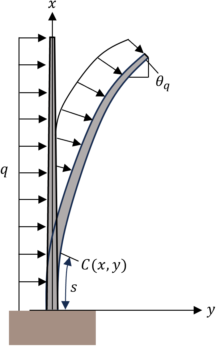
Several experimental studies used the Euler–Bernoulli beam theory to analyse the bending of bamboo culms (Chalermsin & Sato, Reference Chalermsin and Sato2025; Horibe & Mori, Reference Horibe and Mori2018; Mouka et al., Reference Mouka, Dimitrakopoulos and Lorenzo2022; Nishiyama & Sato, Reference Nishiyama and Sato2022); we therefore used the same theory in this study:

We derived the governing equation for a solid tapered beam under a UDL (Figure 2) using the same procedure described by Chalermsin and Sato (Reference Chalermsin and Sato2025), but plugging the dimensionless load
${\alpha}_q=q{L}^3/{E}_{\mathrm{SU}}{I}_{\mathrm{SU}}$
 into the equation, where
${E}_{\mathrm{SU}}$
 is the Young’s modulus and
${I}_{\mathrm{SU}}$
 is the second moment of the area for a solid untapered beam.
Solid tapered beam subjected to a uniformly distributed load with an origin at a fixed end.
$x$
 and
$y$
 are the coordinates of an arbitrary point
$C\left(x,y\right)$
 , and
${\theta}_q$
 is the deflection angle at that arbitrary point.

Optimal tapering ratio of a solid tapered beam under a uniformly distributed load and a point load (Nishiyama & Sato, Reference Nishiyama and Sato2022).
Maximum dimensionless bending stress
${\left(\sigma L/{E}_0{D}_{\mathrm{SU}}\right)}_{\mathrm{max}}$
 of a beam as a function of the tapering ratio
$\gamma$
 under UDL (a) or point load (b) (Nishiyama & Sato, Reference Nishiyama and Sato2022). Determination of the optimal taper
${\left({D}_1/{D}_0\right)}_{\mathrm{opt}}$
 as a function of the dimensionless load
${\alpha}_q$
 under a UDL (c) or
$\alpha$
 under a point load (d).

Figure 3. Long description
The image consists of four panels labeled A through D.
Panel A: A line graph for U D L showing maximum dimensionless bending stress (sigma L over E sub 0 D sub S U) max on the y-axis from 0 to 2, against tapering ratio gamma (D sub 1 over D sub 0) on the x-axis from 0 to 1. Four upward-curving black lines represent alpha sub q values of 2, 4, 6, and 8. A red line with x-markers intersects the minima of these curves, labeled Optimal taper, showing the optimal gamma decreases slightly as alpha sub q increases.
Panel B: A similar graph for Point load. The curves are more pronouncedly U-shaped. The red Optimal taper line shows a steeper negative slope, indicating the optimal tapering ratio gamma increases significantly as the dimensionless load alpha decreases.
Panel C: A line graph for U D L showing optimal taper (D sub 1 over D sub 0) opt on the y-axis from 0 to 0.6 against alpha sub q on the x-axis from 0 to 8. A dotted line with x-markers shows a slight linear decrease. The regression equation is y equals minus 0.0095 x plus 0.247 with an R-squared of 0.9985.
Panel D: A line graph for Point load showing optimal taper on the y-axis against alpha on the x-axis. A dotted line with x-markers shows a steeper linear decrease than in Panel C. The regression equation is y equals minus 0.0415 x plus 0.5555.
The governing equation of a solid tapered beam under a UDL is then defined as:

where
$F\left(\xi \right)$
 follows Eq. (2). By differentiating
$F\left(\xi \right)$
 with respect to
$\xi$
 , we obtained the following equation:

4. Case of a hollow tapered beam
Using the same procedure as above, we expressed the governing equation of a hollow tapered beam under a UDL as:

where
$\omega \left(=t/{D}_{\mathrm{H}{\mathrm{T}}_{\mathrm{o}}}\right)$
 is the thickness of the beam divided by its outer diameter (
$0<\omega \le 0.5$
 ),
$F\left(\xi \right)$
 and
$dF\left(\xi \right)/ d\xi$
 follows Eqs. (2) and (5), respectively.
Chalermsin and Sato (Reference Chalermsin and Sato2025) and Nishiyama and Sato (Reference Nishiyama and Sato2022) summarised the entire algorithm used to solve the governing equations of both solid and hollow tapered beams. To calculate the governing equations (Eqs. (4) and (6)) of a beam under a UDL, we applied the Runge–Kutta method to obtain the numerical solutions. We solved these calculations by first setting initial conditions: the origin was set at the fixed end,
$\theta \left(\xi =0\right)=0$
 and
$d\theta (0)/ d\xi ={\theta}_0^{\prime }$
 , where
${\theta}_0^{\prime }$
 represents the unknown curvature of the neutral axis at the fixed end. We selected an arbitrary value for
${\theta}_0^{\prime }$
 and ran the calculations through to the free end at
$\xi =1$
 . We checked whether the resulting curvature at the free end
${\theta}_1^{\prime }$
 was zero; if it was different from 0, we corrected
${\theta}_0^{\prime }$
 using the Regula–Falsi method and iterated this calculation until
${\theta}_1^{\prime }$
 was below the allowable error
$\varepsilon ={10}^{-10}$
 . We validated the method and equations derived in this study by calculating deflected angles using the governing equation for a UDL. The calculated angles corresponded perfectly to the results reported by Xiao (Reference Xiao2011) and Chalermsin and Sato (Reference Chalermsin and Sato2025). Xiao (Reference Xiao2011) investigated the large deflection of a beam subjected to UDL and obtained deflected angles using the homotopy analysis method, a mathematical technique used for solving nonlinear equations. Chalermsin and Sato (Reference Chalermsin and Sato2025) analysed the large deflection of hollow tapered axially functionally graded beams under a UDL.
5. Results and discussion
$\gamma$
 is the parameter that returns the smallest value for dimensionless bending stress
${\left(\sigma L/{E}_0{D}_{\mathrm{SU}}\right)}_{\mathrm{max}}$
 at each
${\alpha}_q$
 and
$\alpha$
 value;
$\gamma$
 refers to the optimal taper
${\left({D}_1/{D}_0\right)}_{\mathrm{opt}}$
 , where
${\alpha}_q$
 and
$\alpha$
 represent a dimensionless load of UDL and point load, respectively (Figure 3). The optimal taper
${\left({D}_1/{D}_0\right)}_{\mathrm{opt}}$
 of a beam subjected to a UDL or a point load can be calculated for homogeneous beam (
${E}_{10}=1$
 ) using Eqs. (7) and (8) (Nishiyama & Sato, Reference Nishiyama and Sato2022), respectively (Figure 3c, d):


The solutions of these equations show that a point load is accompanied by a steeper gradient than a UDL, suggesting that the optimal tapering ratio for a UDL does not vary much as the load rises. We also solved the equations for
${E}_{10}=2$
 , which returned a gradient approximately half that for
${E}_{10}=1$
 (UDL,
${E}_{10}=1$
 :
${\left({D}_1/{D}_0\right)}_{\mathrm{opt}}=-0.0095{\alpha}_q+0.247$
 ,
${E}_{10}=2$
 :
${\left({D}_1/{D}_0\right)}_{\mathrm{opt}}=-0.005{\alpha}_q+0.24$
 ). The solid case (
$\omega =0.5$
 ) is used here to isolate the effect of the modulus gradient, since hollowing itself already reduces the load-sensitivity of the optimal taper. For
${E}_{10}=1$
 , as
$\alpha$
 increases from 1 to 10,
${\left({D}_1/{D}_0\right)}_{\mathrm{opt}}$
 falls from 0.238 to 0.152; for
${E}_{10}=2$
 it falls only from 0.235 to 0.19. The variation across the load range is thus reduced by approximately 48%. A comparable reduction (47%) is obtained at
$\omega =0.1$
 , indicating that the effect is not specific to the solid cross-section. The axial modulus gradient therefore reduces the sensitivity of the optimal tapering ratio to load magnitude, in the same qualitative manner as hollowing. The value
${E}_{10}=2$
 approximates the measured modulus ratio of 1.6–1.7 (Amada et al., Reference Amada, Munekata, Nagase, Ichikawa, Kirigai and Yang1996; Suzuki, Reference Suzuki1948).
To incorporate the effect from a hollow beam, we considered Eq. (6), from which the optimal taper
${\left({D}_1/{D}_0\right)}_{\mathrm{opt}}$
 for a UDL or for a point load can be calculated with Eqs. (9) and (10) (Nishiyama & Sato, Reference Nishiyama and Sato2022), respectively (Figure 4):


Optimal tapering ratio of unsheltered (open-grown) and sheltered (dense-stand) plants.
3D plot of the optimal tapering ratio
${\left({D}_1/{D}_0\right)}_{\mathrm{opt}}$
 for a homogeneous beam (
${E}_{10}=1$
 ) as a function of dimensionless load (
${\alpha}_q$
 or
$\alpha$
 ), and the hollowing ratio
$\omega$
 under a UDL q
$\left(\mathrm{a}\right)$
 or point load
$P\;\left(\mathrm{b}\right)$
 (Nishiyama & Sato, Reference Nishiyama and Sato2022). We determined that a UDL reduces the overall variation of optimal taper
${\left({D}_1/{D}_0\right)}_{\mathrm{opt}}$
 in the 3D landscape. Furthermore, a value of
$\omega =0.5$
 describes a solid beam, while a declining hollowing ratio
$\omega$
 results in a hollower beam (Figure 4). Note that these results describe the behavior of a homogeneous beam
$\left({E}_{10}=1\right)$
 for which the Young’s modulus is the same from the base to the tip.

Figure 4. Long description
A two-panel 3D plot visualization.
Panel A, titled Unsheltered plants: Uniformly distributed load, shows a relatively flat, slightly sloped surface.
* The vertical Z-axis represents the optimal tapering ratio (D sub 1 / D sub 0) sub opt, ranging from 0 to 0.3.
* The X-axis represents Dimensionless load alpha sub q (= q L super 3 / E sub S U I sub S U), ranging from 0 to 10.
* The Y-axis represents Hollowing ratio omega, ranging from 0 to 0.5.
* The surface is colored in shades of blue and purple, indicating low optimal tapering values across the entire parameter space.
Panel B, titled Sheltered plants: Point load, shows a more dynamic, steeply sloped surface.
* The vertical Z-axis represents (D sub 1 / D sub 0) sub opt, ranging from 0 to 0.6.
* The X-axis represents Dimensionless load alpha (= P L super 2 / E sub S U I sub S U), ranging from 0 to 10.
* The Y-axis represents Hollowing ratio omega, ranging from 0 to 0.5.
* The surface transitions from red (high values near 0.5) at low alpha and high omega, to blue (low values near 0.2) at high alpha and low omega. A specific data point is highlighted with a red box showing 0.25.
Between the panels is a vertical color scale for (D sub 1 / D sub 0) sub opt, ranging from purple (0.2) at the bottom to red (0.5) at the top.
To the right of Panel B, three cylinder diagrams illustrate the physical meaning of the variables:
* A cylinder with alpha = 1 (low load).
* A cylinder with alpha = 10 (high load).
* A hollow cylinder representing the hollowing ratio omega.
Optimal tapering ratio versus hollowing ratio, compared with morphological data for Moso bamboo (Zhang et al., Reference Zhang, Chu, Gao, Ding, Que, Ahmad, Yu, Ramakrishnan and Wei2024).
This figure compares the actual geometries of Moso bamboo culms (Zhang et al., Reference Zhang, Chu, Gao, Ding, Que, Ahmad, Yu, Ramakrishnan and Wei2024) with the theoretically derived
${\left({D}_1/{D}_0\right)}_{\mathrm{opt}}$
 equation. The tapering ratio and thickness-to-diameter ratio
$\omega$
 of Moso bamboo are represented as red crosses and were calculated by dividing the minimum diameter by the maximum diameter of the internodes from the base to the first branch for the tapering ratio and the thickness at the base by the diameter at the base for
$\omega$
 . These are extreme values pooled across culms in each population, so per-culm tapering ratios bellow the first branch are likely higher.

Figure 5. Long description
A line graph with X-axis ‘Hollowing ratio omega’ from 0 to 0.5 and Y-axis ‘Optimal tapering ratio (D sub 1 / D sub 0) sub opt’ from 0 to 0.6.
* The graph features several curves for alpha values ranging from 2 to 12.
* A solid black horizontal line labeled U D L (Uniformly Distributed Load) sits at a tapering ratio of approximately 0.25.
* Above this, a shaded gray region represents ‘Point load’ conditions, where tapering ratio curves descend as omega increases.
* Red crosses representing Moso Bamboo data are clustered between omega 0.13 and 0.16 and tapering ratios 0.35 to 0.55.
* A vertical dashed red line marks omega equals 0.25.
* An orange box with an upward arrow indicates ‘Resistance to point load’ near the bamboo data cluster.
* A green horizontal arrow at the top points left, labeled ‘Robust to various loading conditions’.
* To the left of the graph, a diagram shows a hollow tapered cylinder with alpha equals 2 to 12 and (D sub 1 / D sub 0) sub opt approximately 0.5.
* To the right, two tapered cylinder diagrams illustrate specific points: the top one for alpha equals 4 with a ratio of 0.4, and the bottom one for alpha equals 10 with a ratio of 0.15.
The results in Fig. 4 indicate that the hollower a beam is, the smaller the variation in the optimal taper
$(D_1/D_0)_{\mathrm{opt}}$
 will be as load strength changes, while raising
$E_{10}$
will lower the overall variation of
$(D_1/D_0 )_{\mathrm{opt}}$
. For a solid (i.e., not hollow) beam structure, the optimal taper
$(D_1/D_0 )_{\mathrm{opt}}$
varies significantly for each loading condition. For example,
$(D_1/D_0 )_{\mathrm{opt}} = 0.4$
for
$\alpha = 4$
and
$(D_1/D_0 )_{\mathrm{opt}} = 0.15$
for
$\alpha = 10$
(Fig. 5), which indicates that a beam must be more tapered to optimally limit the stress imposed by higher loads. However, for a very hollow structure, such as with
$\omega = 0.05, a (D_1/D_0 )_{\mathrm{opt}}$
of approximately 0.5 will correspond to
$\alpha = 2 - 12$
. In terms of structural mechanics, this result suggests that a hollow structure with axially FGM exhibits dominant structural properties, as it can minimize bending stress over a wide range of loading conditions. This robustness across various loading conditions distinguishes hollow structures from solid designs, which require optimisation for each specific loading case.
Nishiyama and Sato (Reference Nishiyama and Sato2022) previously calculated
${\left({D}_1/{D}_0\right)}_{\mathrm{opt}}$
for a homogeneous beam (
${E}_{10}=1$
 ) under point load (Figure 4b). A comparison of the
${\left({D}_1/{D}_0\right)}_{\mathrm{opt}}$
 values for a beam under a UDL with those for a beam subjected to point load, as expressed by Eqs. (9) and (10), respectively, indicated that the gradient of a beam under point load is approximately 4.4 times greater than that of a beam under a UDL. This finding suggests that as the load increases, the optimal taper varies much more for a beam under point load than for a beam under a UDL.
Surprisingly, actual bamboo data exhibit two distinct superior mechanical properties independently arising from hollowness and tapering as follows. In terms of hollowness, the
$\gamma$
 values from six-year-old Moso bamboo plants collected from 16 sampling regions in China, measured from the base to the first branch, ranged from
$0.4$
 to
$0.53$
 , with
$\omega \approx 0.13-0.16$
 and one outlier at
$\omega \approx 0.25$
 (Zhang et al., Reference Zhang, Chu, Gao, Ding, Que, Ahmad, Yu, Ramakrishnan and Wei2024) (red crosses in Figure 5), which might be due to differences in the growing environment. This indicates that bamboo, with its low hollowing ratio, is robust against diverse loading conditions, a single taper remains near optimal as load varies, rather than requiring re-optimisation for each case (horizontal arrow in Figure 5). In terms of tapering, the optimal taper value
${\left({D}_1/{D}_0\right)}_{\mathrm{opt}}$
 for
$\omega <0.25$
 under a UDL was approximately 0.2 (Figure 5 bottom). Under point load,
${\left({D}_1/{D}_0\right)}_{\mathrm{opt}}$
 ranged from 0.3 to 0.5 (Nishiyama & Sato, Reference Nishiyama and Sato2022) (Figure 5 top), which is in good agreement with
$\gamma$
 values previously reported by Zhang et al. (Reference Zhang, Chu, Gao, Ding, Que, Ahmad, Yu, Ramakrishnan and Wei2024) (red cross and black lines in Figure 5). This indicates that bamboo, with its high optimal tapering ratio (less tapered), exhibits superior mechanical properties in terms of tapering, providing greater stress resistance to point load than to a UDL (vertical arrow in Figure 5). These two superior mechanical properties are reasonable because bamboo plants typically grow close together in dense stands, where other plants and neighbouring culms act as shelter; the loading condition becomes more point-load dominated than UDL.
The optimal tapering law suggests that unsheltered (open-grown) hollow tapered plants will be more tapered than sheltered (dense-stand or forest-grown) plants. The maximum optimal tapering ratio of a beam was
$0.3$
 under a UDL (Figure 4a) and
$0.6$
 for a point load (Figure 4b). Thus, under the optimal tapering law, unsheltered plants will be more tapered than sheltered plants, perhaps to minimise the concentration of stress at the base of the stem or culm and prevent uprooting. Horibe and Mori (Reference Horibe and Mori2018) found that for beams subjected to point load, the maximum stress shifted away from the base when
$\gamma <2/3\approx 0.67$
 , while Chalermsin and Sato (Reference Chalermsin and Sato2025) reported the corresponding threshold under a UDL to be
$\gamma <1/3\approx 0.33$
 . The maximum optimal tapering ratios were below their respective thresholds, namely
$0.3<0.33$
 for a UDL and
$0.6<0.67$
 for point load, suggesting that the optimal tapering ratios shift the point with the greatest bending stress away from the base. As the tapering ratio of Moso bamboo culms below the first branch fits the optimal tapering ratio, we conclude that bamboo culms are tapered to shift stress away from their bases. However, reasons other than shifting stress may also help explain the observed tapering ratio; studies are needed to assess how tapering and hollowing affect the distribution of bending stress along the culm.
The optimal tapering law identified in this study is the idealised tapering ratio that minimises stress on a beam, suggesting that tapered and hollow bamboo culms are stress efficient. However, bamboo morphology is the result of evolutionary pressure on multiple factors rather than just optimisation to minimise load stress. In addition to mechanical support, the culm must maintain vascular function, transporting water and nutrients between the roots and leaves, which imposes critical biological constraint and is not captured by the purely mechanical model used here. To biomimic bamboo, many factors must be considered, including branches, biological function and the distribution of vascular bundles, shear effects and the distribution of nodes. The results of this study are helpful for understanding the natural structure of trees in general and bamboo culms in particular, as well as the consequences of tapering and hollowing stems to minimise stress. The present model is also geometrically idealised. Measured Moso culms show some variation in the thickness-to-diameter ratio, from approximately 0.15 at the base to 0.1 near the first branch (Zhang et al., Reference Zhang, Chu, Gao, Ding, Que, Ahmad, Yu, Ramakrishnan and Wei2024), though this depends on the growing environment. The variation is modest, and the hollow ratio is therefore treated here as constant along the culm. A consequence is that the taper ratio is the only geometric quantity optimised, the model yields an optimal taper ratio as a function of the thickness-to-diameter ratio and the load magnitude, but cannot predict how wall thickness should vary along the culm. The optimal tapering law derived here is especially crucial for structural design for greater construction efficiency and reduced material consumption. Furthermore, our findings emphasise the importance of considering the load type when designing materials.
6. Conclusion
We derived the optimal tapering law that describes bamboo culms and examined how the culm’s hollow, tapered structure made from axial FGMs affects bending stress under a UDL. We then compared the results to those obtained for a beam subjected to point load. The optimal tapering law is defined as the tapering ratio that minimises maximum bending stress under external loading and incorporates the hollowing ratio. Bamboo follows point-load-dominated conditions and is hollow to minimise bending stress across a wide range of loading conditions and tapered to shift the position of maximum stress away from the base. We determined that the degree of hollowness and tapering of Moso bamboo culms below the first branch follows the optimal tapering law, which determines the optimal combination of tapering and hollowing ratios to achieve mechanical robustness in minimising stress in particular growing environments. This suggests that bamboo culms are morphologically optimised through evolution for their respective growing environments.
Open peer review
To view the open peer review materials for this article, please visit http://doi.org/10.1017/qpb.2026.10055.
Acknowledgements
The authors thank the anonymous reviewers for their careful reading and constructive comments, which improved the manuscript.
Author contributions
C.L.C., S.T., and M.S. conceived and designed the study and conducted the analysis and interpretation. C.L.C. contributed to the literature collection, method development, formulation, numerical calculations and manuscript preparation. S.T. contributed to the interpretation of data, discussion and provided useful guidance on the research and manuscript. M.S. supervised the project. All authors contributed to writing the manuscript.
Competing interest
On behalf of all the authors, the corresponding author states that there are no conflicts of interest.
Data availability statement
All data generated or analysed during this study are included in this published article.
Funding statement
This work was supported by the Iketani Science and Technology Foundation.




 Open access


Comments
17/06/2026
Olivier Hamant
Editor-in-Chief
Quantitative Plant Biology
Dear Editor,
I wish to submit an original article for publication in the Quantitative Plant Biology, titled “Why bamboo culms are hollow and tapered cylinders” The paper was coauthored by Carol Lee Chalermsin and Satoru Tsugawa.
In this study, we aimed to answer why tall plant stems such as bamboo culms typically hollow and tapered, a geometry that, at first glance, appears mechanically counterintuitive given the known susceptibility of thin-walled tubes to ovalization (flattens) under bending. Through a theoretical framework grounded in mechanics of materials, we derived ‘optimal tapering law’ of a beam, with consideration of the hollowing ratio and loading conditions to minimize the maximum bending stress. Our law reveals that hollow structure makes the optimal taper largely insensitive to load magnitude, “providing mechanical robustness against environmental variability”. Tapering “prevent stress concentration at the base,” enhancing resistance to point loading typical of dense forest-like growth conditions. A comparison of Moso bamboo morphological data with the theoretically predicted optimal tapering ratios showed strong agreement, suggesting that bamboo culms are morphologically optimized through evolution for their respective growing environments.
We believe this work is well suited to the broad readership of Quantitative Plant Biology for several reasons. First, it offers a quantitative explanation for the hollow, tapered architecture of bamboo culms, advancing the biomechanical understanding of how natural stems minimize stress through tapering and hollowing. Second, it bridges plant biomechanics and structural mechanics by showing that a simple analytical principle can account for an observed biological geometry. Third, the derived law is directly applicable to structural design, where it can inform the design of components for greater construction efficiency and reduced material consumption. Finally, the analysis emphasizes that load type must be considered explicitly when designing graded, hollow materials. We believe that our manuscript is within the scope of Quantitative Plant Biology and expect that knowledge in the field of structural mechanics and biomimetics can potentially lead to further studies and structural designs.
This manuscript has not been published or presented elsewhere in part or in entirety and is not under consideration by another journal. We have read and understood your journal’s policies, and we believe that neither the manuscript nor the study violates any of these. There are no conflicts of interest to declare.
Thank you for your consideration. I look forward to hearing from you.
Sincerely,
Motohiro Sato
Faculty of Engineering
Hokkaido University
Kita 13, Nishi 8, Kita-ku,
Sapporo, 060-8628, Japan
Tel: (+81)11-706-6367
Fax: (+81)11-706-7895
E-mail: tayu@eng.hokudai.ac.jp