I. INTRODUCTION
Alloy nanomaterials have attracted much attention due to their diverse range of physical properties and potential applications in optics,Reference Kelly, Coronado, Zhao and Schatz1 magnetics,Reference Bautista, Bomati-Miguel, Zhao, Morales, González-Carreño, Pérez de Alejo, Ruiz-Cabello and Veintemillas-Verdaguer2–Reference Paduani5 catalytic activity,Reference Roucoux, Schulz and Patin6–Reference Mathauser and Teplyakov10 hydrogen storage,Reference Kirchheim, Mutschele, Keininger, Gleiter, Birringer and Koble11, Reference Kamakoti and Sholl12 electrochemistry,Reference Menon and Martin13 and biotechnology.Reference Subramoney14 As an important transition metal alloy, NiCo has been widely used for decoration, corrosion resistance, and magnetic recording devices.Reference Wu, Quan, Liu, Ma, Dai and Zhang15 It was reported that magnetic properties and catalytic activity are affected by the composition and size of NiCo nanoparticles.Reference Wu, Cao, Li, Ni, Zhu and Zhang16–Reference Ramaye, Neveu and Cabuil23 For example, for a decrease in the particle size, there is an increase in magnetic recording density. From the view points of fundamental as well as applied research, it is interesting to study the structure and properties of NiCo alloys.
Nanoparticles of transition metals have properties that are significantly different from those of the corresponding bulk materials. However, investigations and applications of these nanomaterials are restricted because they have great affinity toward oxygen and ignite spontaneously in air even at room temperature (RT). The studies of the nanoparticles must therefore be performed in situ at ultrahigh vacuum or in reducing or inert atmospheres.Reference Bdker, Mørup and Linderoth24 Nevertheless, it is possible to introduce metals inside the hollow of carbon nanotubes (CNTs). This approach offers a way to protect the nanoparticles from the environment. However, the introduction of dopants may significantly alter the conducting, electronic, or mechanical behavior of CNTs. The structural order and morphology of CNTs, which are critical factors in determining CNT characteristics may be affected by the shape and size of the enwrapped particles. It was reported that the field-emission property of multiwalled CNTs (MWCNTs) could be enhanced by controlling the atomic structure at the tip surface.Reference Kuzumaki, Takamura, Ichinose and Horiike25, Reference Zhi, Bai and Wang26 When MWCNTs were used for hydrogen storage, its structure and crystallinity had an effect on storage capacity.Reference Chamber, Park, Baker and Rodriquez27 It was also observed that the amount of Li ions electrochemically inserted into defective MWCNTs is higher than that inserted into MWCNTs of higher crystallinity.Reference Dahn, Zheng, Liu and Xue28
Fabricated composite materials of alloy and CNTs are commonly used in technologies such as magnetic data storage devices,Reference Terrones, López-Urías, Muñoz-Sandoval, Rodríguez-Manzo, Zamudio, Elías and Terrones29–Reference Elías, Rodríguez-Manzo, McCartney, Golberg, Zamudio, Baltazar, López-Urías, Muñoz-Sandoval, Gu, Tang, Smith, Bando, Terrones and Terrones32 fuel cells,Reference Steigerwalt, Deluga and Lukehart33, Reference Che, Lakshmi, Martin and Fisher34 electromagnetic wave absorption,Reference Wu, Zhao and Jiao35–Reference Lv, Kang, Gu, Gui, Wei, Wang and Wu37 field-emission,Reference Lv, Kang, Zhu, Zhu, Gui, Wei, Gu, Li, Wang and Wu38 sensors for magnetic force microscopy,Reference Winkler, Muhl, Menzel, Kozhuharova-Koseva, Hampel, Leonhardt and Büchner39 and human tumor therapy.Reference Mönch, Meye, Leonhardt, Krämer, Kozhuharova, Gemming, Wirth and Büchner40, Reference Korneva, Ye, Gogotsi, Halverson, Friedman, Bradley and Kornev41 In the last decade, various techniques have been developed to encapsulate metals, alloys, metal oxides, and chlorides in MWCNTs or single-walled CNTs.Reference Grobert, Mayne, Terrones, Sloan, Dunin-Borkwski, Kamalakaran, Seeger, Terrones, Rühle, Walton, Kroto and Hutchison42–Reference Sloan, Wright, Woo, Brown, York, Coleman, Hutchison and Green44 The presence of CoNi nanoparticles inside carbon nanomaterials have been reported previously by SudaReference Suda, Tanaka, Okita, Sakai and Sugawara45 and Gorbunov et al.,Reference Gorbunov, Just, Pompe and Graff46 and the role of catalyst species and the effect of catalyst particle size in the synthesis of carbon material are discussed. Herein, we report the encapsulation of NiCo nanoparticles in CNTs by in-situ catalytic decomposition of benzene in an Ar atmosphere at 500 °C over freshly prepared NiCo nanoparticles. The structure and magnetic properties of the composites (i.e., NiCo alloy nanoparticles encapsulated in carbon nanomaterials) were studied in detail.
II. EXPERIMENTAL
The experimental setup and procedure are similar to that described in our previous report,Reference Xu, Qi, Zhong, Ye, Deng, Au, Jin, Yang and Du47 using NiCo as catalyst rather than Fe in the present study. Two steps were used to synthesize the composites: (i) the preparation of NiCo nanoparticles and (ii) the synthesis of CNTs and carbon nanorods (CNRs) with NiCo nanoparticles encapsulated in them.
All the reagents were of analytical grade and used as received. To prepare the CoNi nanoparticles, 0.03 mol NiCl2·6H2O, quantitative amount of CoCl2·6H2O (Ni:Co atomic ratios = 1:3, 2:2, and 3:1), and 0.045 mol citric acid monohydrate were dissolved in 250 mL absolute ethanol, and the mixture was stirred at 60 °C for 6 h. The as-obtained mixture was kept at 80 °C for several hours and then heated to 150 °C for the generation of a xerogel. Subsequently, the xerogel was heated in air at 500 °C for 4 h for the generation of nickel cobalt oxide (i.e., NiO/Co2O3 powder). For the generation of NiCo/CNT and NiCo/CNR composites, we used a quartz tube reactor (6 cm in inner diameter and 75 cm in length), equipped with temperature and gas-flow controls. The NiO/Co2O3 powder (30 mg, spread on a ceramic plate) was placed inside the reactor and reduced (in H2 at 500 °C for 4 h) until the formation of nickel–cobalt nanoparticles. The NiCo nanoparticles obtained with Ni:Co atomic ratios equal to 1:3, 2:2, and 3:1 are denoted hereinafter as NiCo13, NiCo22, and NiCo31, respectively. Then, benzene (kept in a three-necked flask maintained at 70 °C in a water bath) was carried into the reactor by an argon flow. The decomposition of benzene was conducted in situ over the NiCo nanoparticles at 500 °C for 6 h, and after cooling to RT, the as-generated composites (black in color) were collected (denoted hereinafter as NiCo13@C, NiCo22@C, and NiCo31@C, respectively).
The samples were examined at RT on an x-ray powder diffractometer (XRD) for phase identification using Cu Kα radiation (Model D/Max-RA; Rigaku, Tokyo, Japan). Sample morphology was studied using a high-resolution transmission electron microscope (HR-TEM) (model JEOL-2010; Tokyo, Japan) operated at an accelerating voltage of 200 kV and a field-emission scanning electron microscope (FE-SEM) (model 1530VP; LEO, Munich, Germany, equipped with a JEOL JFC-1600 auto fine-coater, Tokyo, Japan) operated at an accelerating voltage of 5 kV. The magnetic properties of samples were investigated at RT over a Quantum Design MPMS SQUID magnetometer (Quantum Design MPMS-XL San Diego, CA). Thermogravimetry analysis (TGA) was carried out on a thermal analysis system (Perkin-Elmer TGA7 series, Waltham, MA) with approximately 5.0 mg of sample heated in air at a rate of 10 °C min−1. Raman spectroscopy investigations were performed over a Jobin-Yvon Labram HR800 instrument (Jobin Yvon Corporation, Paris, France) with 514.5-nm Ar+-laser excitation. Fourier transform infrared spectroscopy of samples (in KBr pellets) was recorded using a Nicolet 510P spectrometer (ThermoNicolet Instrument Corporation, Madison, WI).
III. RESULTS AND DISCUSSION
In this study, 30 mg of the NiO/Co2O3 powder (giving approximately 21.61, 22.01, and 22.62 mg of NiCo13, NiCo22, and NiCo31, respectively) was used, and about 0.459, 0.304, and 1.437 g of NiCo13@C, NiCo22@C, and NiCo31@C composites were harvested in each run, respectively. The yield of NiCo31@C is the highest among the three samples.
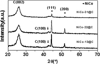
The XRD patterns of NiCo13@C, NiCo22@C, and NiCo31@C are shown in Fig. 1. Reflections at 26.22° and 42.43° can be attributed, respectively, to (002) and (100) planes of hexagonal graphite (JCPDS Card File No. 41-1487, lattice parameters a = 2.470 Å and c = 6.756 Å), denoting the formation of graphitic species. In the case of NiCo31@C, the (100) signal is missing. Reflections at 44.35° and 51.68° can be indexed, respectively, to (111) and (200) planes of NiCo alloy (JCPDS Card File No. 65-2865).Reference Feng, Zhao, Du, Song, Song and Zhu48 Using the Scherrer formula and the full width at half maximum of the (111) peak, the average grain size of NiCo alloy is estimated to be 24.9, 24.9, and 11.2 nm for NiCo13@C, NiCo22@C, and NiCo31@C, respectively.
X-ray diffraction patterns of NiCo13@C, NiCo22@C, and NiCo31@C.

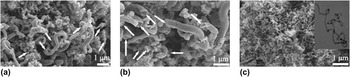
Representative FE-SEM images of the NiCo13@C, NiCo22@C, and NiCo31@C composites are shown in Fig. 2. One can see mass amount of one-dimensional (1D) nanomaterials that are morphologically irregular. In the cases of NiCo13@C and NiCo22@C, the products are curly CNRs several microns in length and 250–625 nm in diameter [Figs. 2(a) and 2(b)]. A close inspection reveals that the CNRs are hollow (indicated by arrows) and are made up of nanorings stacking one by one either closely or loosely. One can see that along each rod, it is not uniform in diameter. On the basis of the FE-SEM images, we estimated the selectivity to CNRs is approximately 90 and 95% for NiCo13@C and NiCo22@C, respectively. Shown in Fig. 2(c) are the FE-SEM and TEM images (inset) of NiCo31@C. One can see mass amount of MWCNTs with crystallinity higher than that of NiCo13@C and NiCo22@C. The MWCNTs are 50–100 nm in diameter and cannot be considered as CNRs. The FE-SEM images of the as-generated composites indicate that the products of benzene decomposition over the NiCo nanoparticles are dependent on the Ni:Co molar ratio, showing morphologies that are different from one another. Such a result is different from that of Fe–Ni nanoparticlesReference Xu, Zhong, Qi, Au, Deng and Du49 because there is no direct relationship between product morphology and composition of the Fe–Ni nanoparticles.
Field-emission scanning electron microscope images of (a) NiCo13@C, (b) NiCo22@C, and (c) NiCo31@C (inset: transmission electron microscopy (TEM) image of NiCo31@C).

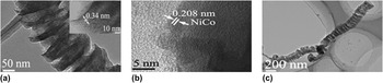
Figure 3 shows the HR-TEM micrographs of NiCo13@C and NiCo22@C. One can see the bellow-like (corrugated tube) feature of CNRs [Figs. 3(a) and 3(c)], and the interplanar distance is approximately 0.34 nm [inset of Fig. 3(a)], which is consistent with the interplanar distance of graphitic layers, and the NiCo nanoparticles are indeed present inside CNRs [pitch black part of Fig. 3(c)]. The lattice edges of NiCo alloy are about 0.208 nm [Fig. 3(b)], in good agreement with the interlayer separation of the (111) crystal planes of NiCo alloy.
High-resolution TEM images of (a) NiCo22@C (Inset: interplanar distance), (b) surface of a NiCo nanoparticle, and (c) NiCo13@C.

The exact mechanism for the formation of such a carbon nanostructure via catalytic chemical vapor deposition (CCVD) is not properly known. In fact, the growth mode of carbon nanomaterials remains an open topic in CCVD-based techniques.Reference Merkulov, Melechko, Guillorn, Lowndes and Simpson50 During CCVD processes, the catalyst nanoparticles can exhibit two completely different behaviors; they can remain on the substrate or be lifted off the substrate. The former is called ‘‘base-growth’’Reference Fan, Chapline, Franklin, Tombler, Cassell and Dai51 while the latter ‘‘tip-growth’’ mode.Reference Amelinckx, Zhang, Bernaerts, Zhang, Ivanov and Nagy52 The difference of growth mode is often explained in terms of adhesion force between the catalyst and the substrate. Understandably, a weak contact favors the tip-growth mode, whereas a strong interaction promotes the base-growth mechanism.Reference Song, Cho, Choi, Park and Kim53, Reference Bower, Zhou, Zhu, Werder and Jin54 Besides such a conventional understanding, Gohier et al.Reference Gohier, Ewels, Minea and Djouadi55 suggested that the growth mode can be influenced by the interaction between small carbon patches (polyaromatic carbon or reticulated carbon chains) and catalyst particles, and CNT growth switches from tip-growth to base-growth with decreasing size of catalyst particles. Du et al.Reference Du, Feng, Zhao, Song, Bai and Zhu56 considered that the evolution of CNTs in CCVD synthetic processes follows a mechanism of particle–wire–tube evolution, disregarding the conventional adsorption–diffusion–precipitation (ADP) mechanism that was extended from the solid-catalyst-involved synthetic process. Furthermore, Wang et al. proposed that over Fe and Ag nanoparticles, CNRs are formed through the assembly of clusters of 1D conjugate carbon chains originated from free C2 entities [tetrachloroethylene (C2Cl4) is reduced by metallic potassium to free C2 through the removal of chlorine atoms].Reference Wang, Lu, Xie, Du and Guo57 Based on the model of Gamaly and Ebbesen,Reference Gamaly and Ebbesen58 Zou et al. suggested that at moderate and low distribution velocities of carbon atoms on catalyst surfaces, CNRs and CNTs are, respectively, formed.Reference Zou, Lu, Wang, Xu and Qian59
With due consideration to the above understandings and on the basis of our experimental results, we propose that the morphology of products is dependent on the size of NiCo nanoparticles as well as on the hexagonal graphite phase of composites. According to XRD results, the average grain size of NiCo31 (11.2 nm) is smaller than that of NiCo13 (24.9 nm) and NiCo22 (24.9 nm). On the other hand, the XRD results reveal that in the cases of NiCo13@C and NiCo22@C there are (002) and (100) planes of hexagonal graphite, whereas in the case of NiCo31@C there is only (002) plane. The morphology of NiCo13@C and NiCo22@C is CNRs while that of NiCo31@C is CNTs. It is apparent that the growth of CNRs is better facilitated over NiCo13 and NiCo22, which are bigger than NiCo31 in particle size. We tentatively suggest a mechanism for the formation of CNRs: (i) breakage of all the benzene C–H bonds and the formation of round graphite rings that contain (002) and (100) planes on the surface of NiCo13 and NiCo22 nanoparticles and (ii) interaction of hexagonal graphite rings with appending bonds at the brim of graphite rings, resulting in the formation of hollow CNRs. With regards to the NiCo31@C composite, we believe that the evolution of CNTs obeys the conventional ADP mechanism and CNTs containing only (002) planes are formed. According to the viewpoint of Gohier et al.,Reference Gohier, Ewels, Minea and Djouadi55 one can consider that there is a variation of particle properties as a function of particle size. With reduction in particle size, a catalyst becomes larger in surface-to-volume atom ratio and hence is chemically more active. The outcome is the formation of carbon patches, which are needed at the early stage of nucleation for CNT generation. In the cases that the catalyst particles are relatively larger in size, some carbon atoms are attached to the surface of the catalysts, forming graphite rings (smaller than the NiCo facets in area) that may be considered as seed structures for the growth of bellow-like feature of CNRs.
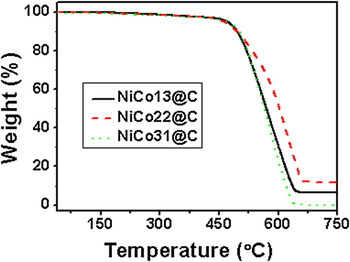
TGA is commonly used to determine the purity of CNR and CNT species. TGA results of the NiCo13@C, NiCo22@C, and NiCo31@C composites are shown in Fig. 4, and one can see major weight losses in the 450–670 °C range, and the total losses amount to 93.6, 87.6, and 99.8 wt% at 655, 670, and 648 °C for NiCo13@C, NiCo22@C, NiCo31@C, respectively. The losses can be ascribed to carbon oxidation, and the residue (6.4, 12.4, and 0.2 wt%, respectively) to NiCo alloy oxide. Nonetheless, from RT to 470 °C, there are losses of 3.42, 3.75, and 4.82 wt% for NiCo13@C, NiCo22@C, and NiCo31@C, respectively. It is a net result of the oxidation of amorphous carbon and NiCo alloy to their oxides. On the basis of the above data, we estimate that the amount of amorphous carbon in the products is 5.16, 6.89, and 4.86 wt%, respectively, for NiCo13@C, NiCo22@C, and NiCo31@C.
Thermogravimetry curves of NiCo13@C, NiCo22@C, and NiCo31@C.

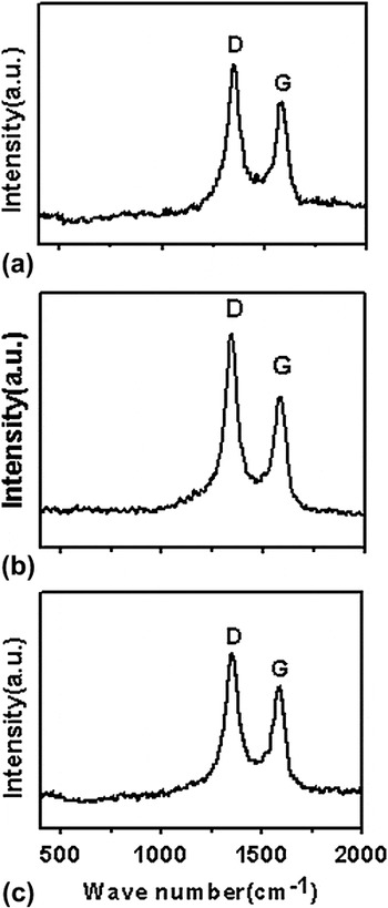
Raman spectroscopy is an important tool for the study of carbon nanomaterials and is a nondestructive technique that provides information about crystal structure and sample disorder.Reference Rao, Richter, Bandow, Chase, Eklund, Williams, Fang, Subbaswamy, Menon, Thess, Smalley, Dresselhaus and Dresselhaus60, Reference Li, Zhang, Wang, Zhang, Xu, Zhu and Xie61 The G-band (in the 1500–1605 cm−1 region) is related to the C–C vibration of the carbon material with sp2 orbital structure,Reference Ivanov, Fonseca, Nagy, Lucas, Lambin, Bernaerts and Zhang62 indicative of graphitic layers of high crystallinity caused by the tangential stretching modes (graphitic lattice mode E2gReference Xie, Li, Pan, Chang and Sun63). The D-band (in the 1250–1450 cm−1 region) is the disorder-induced phonon mode that is related to the mode of boundaries in the Brillouin zone. It is due to the disorder components and mainly due to the phonon mode of the M-point and K-point of the hexagonal Brillouin zone.Reference Mahanandia, Vishwakarma, Nanda, Prasad, Barai, Mondal, Sarangi, Dey and Subramanyam64 Raman spectrum (Fig. 5) of the composites exhibits the D-band as well as the G-band. The D-band of NiCo13@C, NiCo22@C, and NiCo31@C is at 1352.92, 1342.96, and 1352.92 cm−1, respectively, indicating the presence of disorder and/or distortion. The G-band of NiCo13@C, NiCo22@C, and NiCo31@C is at 1580.76, 1584.19, and 1580.76 cm−1, respectively. The intensity ratio (i.e., I D/I G) can be used to assess the crystallinity of carbon materials. In our study, the I D/I G of NiCo13@C, NiCo22@C, and NiCo31@C is approximately 1.27, 1.33, and 1.22, respectively, implying that the increase of defects is in the order of NiCo31@C < NiCo13@C < NiCo22@C. In other words, the NiCo31@C composite is the highest in crystallinity among the three. The result is in good agreement with the TGA result (Fig. 4).
Raman spectra of (a) NiCo13@C, (b) NiCo22@C, and (c) NiCo31@C.

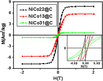
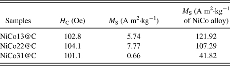
The magnetic hysteresis measurement of the composites was carried out at RT in an applied magnetic field. Figure 6 (M–H curves) shows magnetic hysteresis curves of the composites, and the related results are listed in Table I. The coercivity of NiCo13@C, NiCo22@C, and NiCo31@C is 102.8, 104.1, and 101.1 Oe, respectively, indicating that coercivity is not sensitive to the rise of Ni concentration in the NiCo alloys.
Typical magnetization curves of NiCo13@C, NiCo22@C, and NiCo31@C. The inset shows the enlarged part of the curves close to the origin.

Magnetic parameters of NiCo13@C, NiCo22@C, and NiCo31@C composites.

Table I shows that the saturation magnetization M S (A m2·kg−1 of NiCo alloy) detected over NiCo13@C is the highest (121.92 A m2·kg−1). The M S (A m2·kg−1 of NiCo alloy) rises in the order of NiCo31@C < NiCo22@C < NiCo13@C. The results show that M S decreases with increase of Ni content. This experimental phenomenon may be explained by the energy-band model and the Slater–Pauling curve.Reference Koster and Slater65, Reference Kanamori, Terakura and Yamada66 The Slater–Pauling curveReference Koster and Slater65 indicates that the average magnetic moment of alloy is a function of the amount of outer electrons. The energy-band modelReference Kanamori, Terakura and Yamada66 indicates that in a ferromagnetic alloy, an increase of electron number in the D-band can enhance or decrease electron distribution of energy band and hence change the magnetic moment of the alloy. In this study, the rise of Co in the NiCo alloy reduces electron distribution and hence there is an increasing of magnetic moment.
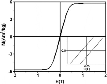
The M–H curve of a NiCo13@C sample that was exposed to ambient environment over 18 months is shown in Fig. 7. A comparison of the data with those of Fig. 6 indicates that there is no significant change in magnetic properties. The M S (approximately 5.74 A m2 kg−1 in Fig. 7) and H C (approximately 102.5 Oe in Fig. 7) of the sample are close to those of Fig. 6 (M S = 5.74 A m2 kg−1, H C = 102.8 Oe). Similar phenomenon was observed over the NiCo22@C and NiCo31@C samples (not shown). In other words, the NiCo particles of the composites are well encapsulated and are effectively protected against oxidation by a wall of graphitic carbon.
M–H curve of NiCo13@C after 18-month exposure to ambient environment. The inset shows enlarged part of the curve close to the origin.

IV. CONCLUSIONS
By means of sol–gel method and hydrogen reduction followed by benzene decomposition, we prepared NiCo/CNR and NiCo/CNT composites that are stable in air. It was found that the size of NiCo nanoparticles and hexagonal graphite phase of composites have an influence on the morphology of products. The composites are highly stable in ambient environment, probably due to the encapsulation of NiCo nanoparticles inside a protective wall of graphitic carbon. The magnetic properties of the NiCo/CNR and NiCo/CNT composites can be optimized by adjusting the composition of the alloy. We envisage that the materials have wide applications in fields such as microwave absorption, magnetic storage, and human tumor therapy.
ACKNOWLEDGMENTS
We thank the National Natural Science Foundation of China (Grant no. 11174132), the National Key Project for Basic Research (Grant nos. 2011CB922102 and 2010CB923402), the National Laboratory of Solid State Microstructures, Nanjing University (Grant no. 2010ZZ18), and the Discipline Crossing Foundation of Nanjing University, People’s Republic of China, for financial support.