I. INTRODUCTION
Laser sintering, also referred to as selective laser sintering (SLS™), is one of the most established powder-based additive manufacturing processes. Laser sintering uses a pulse or continuous laser as a heating source to fuse and join powder materials into predefined geometries. Reference Goodridge, Tuck and Hague1,Reference Hopkinson, Hague and Dickens2 Theoretically, almost any polymer available in powder form can be laser-sintered using optimized processing parameters. However, in reality very few polymers are currently available for laser sintering, which is partly due to the complex thermal behaviors of polymers during the laser sintering process. Reference Kruth, Levy, Klocke and Childs3 At present, polyamides 11 and 12 (PA11/PA12) are the most commonly used laser sintering materials, making up more than 95% of the current laser sintering materials market. Reference Wohlers4
Several other polymers such as polystyrene, polypropylene, polycarbonate, poly(ether-ether-ketone) have been supplied as laser sintering materials. However, currently available materials cannot completely meet the requirements of various functional applications. Reference Goodridge, Tuck and Hague1,Reference Gibson, Rosen and Stucker5 To enhance the properties (mechanical, thermal, electrical, etc.) of laser-sintered parts, nanofillers have been introduced to make polymer nanocomposites (PNCs) in recent years. Reference Goodridge, Shofner, Hague, McClelland, Schlea and Johnson6–Reference Yan, Shi, Yang and Liu14
When comparing nanofillers with conventional fillers, one of the most important differences is the surface-to-volume ratio. Nanofillers have an exceptionally high surface-to-volume ratio and the area at the interface between the matrix and reinforcement phase is much greater than conventional composite materials. This large reinforcement surface area means that a relatively small amount of nanoscale reinforcement can have an observable effect on the macroscale properties of the composite. Reference Mittal15 However, this advantage has not often been observed when processing PNCs by laser sintering. Previous researchers have either found an increase in Young's modulus and ultimate tensile strength (UTS), but a decrease in other properties, such as elongation at break or even a reduction in all properties. Some researchers who have observed an increase in properties have reported that increase against a control PA12 with lower mechanical properties is normally achievable by laser-sintered PA12.
Goodridge et al. Reference Goodridge, Shofner, Hague, McClelland, Schlea and Johnson6 concluded that for laser sintering it is important to maintain the correct powder morphology as well as achieving good dispersion of nanoparticles within the polymer matrix. Thus in our recent study, Reference Bai, Goodridge, Hague and Song16,Reference Bai, Goodridge, Hague, Song and Okamoto17 a novel method to prepare PA12-carbon nanotube (CNT) nanocomposite powder by coating the CNTs onto the surface of PA12 powder particles was used. This allowed the optimized size and near-spherical morphology of the commercial laser-sintering PA12 powder to be retained. Just 0.1 wt.% CNT saw a significant improvement in mechanical properties, including enhanced flexural modulus (+13%), flexural strength (+11%), Young's modulus (+54%), UTS (+6%), and impact strength (+124%) without sacrificing elongation at break. Reference Bai, Goodridge, Hague and Song16 The latter was particularly significant as in previous studies an obvious decrease in elongation at break has been observed for nanocomposite parts compared to neat polymer parts, even though other mechanical properties, such as Young's modulus, UTS, flexural strength, flexural modulus, or impact strength, have been improved. One reason suggested for the decrease in elongation was poor dispersion of filler in the polymer matrix, where filler agglomerates act as defects when a force is loaded. Reference Yan, Shi, Yang and Liu18 As the elongation at break remained the same in our recent study, it would imply that good CNT dispersion was achieved. However, the distribution of CNTs in the laser-sintered PA12-CNT parts was not examined; hence the reason for carrying out this current work.
It is well known that the dispersion and distribution of nanofillers in the polymer matrix are one of the most important factors affecting the properties of the nanocomposites. Reference Ajayan, Schadler, Giannaris and Rubio19,Reference Xie, Mai and Zhou20 Particulate nanofillers tend to form agglomerates very easily, which can weaken the properties of the final nanocomposite parts. Therefore, the nanofillers should be well dispersed in the polymer matrix.
In other research of PNCs for laser sintering, the dispersion of nanofillers has mainly been examined by scanning electron microscopy (SEM) and transmission electron microscopy (TEM). Reference Salmoria, Paggi, Lago and Beal7,Reference Lao, Kan, Lam, Chen, Koo and Moon8 However, traditional SEM and TEM cannot provide nanostructural information in three dimensions. SEM can provide information about the sample's surface topography and composition. The information inside of the sample is lost. Also, it is very difficult to observe the nanofillers on the surface of laser-sintered parts with SEM as the nanofillers are embedded in the polymer matrix. Yan et al. Reference Yan, Shi, Yang and Liu18 used a dissolution–precipitation process to incorporate montmorillonite (3 wt.%) with PA12 to prepare montmorillonite/PA12 nanocomposite for laser sintering. The dispersion of montmorillonite in the PA12 matrix was examined at the fracture surface by SEM. Very rare and unclear montmorillonite was observed. The information underneath the surface of the sample was not reported. In the study carried out by Salmoria et al., Reference Salmoria, Paggi, Lago and Beal7 PA12/CNT (0.5 wt.%) nanocomposites for laser sintering were produced by mechanical mixing. SEM was unable to detect the CNTs from the fracture surface of laser-sintered PA12/CNT parts. Traditional TEM can provide high-resolution information of an ultrathin specimen by projecting three-dimensional (3D) body onto two-dimensional (2D) plane. However, the information along the thickness direction of the sample is lost.
In recent years, electron tomography—3D-TEM has been developed and has become a useful method to provide a 3D characterization of both the surface and the bulk of a material. Reference Frank21–Reference de Jong and Koster24 With this technology, a 3D observation image can be reconstructed by the Fourier transform from a series of 2D-TEM projections, which are collected at different tilt angles. Reference Kohjiya, Katoh, Shimanuki, Hasegawa and Ikeda22 In this work, for the first time, 3D-TEM technology was used to examine laser-sintered PNC parts. The dispersion and distribution of CNTs in the laser-sintered PA12-CNT nanocomposite parts were analyzed.
II. EXPERIMENTAL
A. Materials
The base polymer selected for this study was PA2200® (EOS GmbH, Krailling, Germany, and NanoAmor Materials Inc., Houston, TX), a PA12 material, which has an established use in the laser sintering process. Multiwalled CNTs were supplied by NanoAmor Materials Inc., which had an average diameter of 10 nm and length of 1.5 μm according to the manufacturing datasheet. The PA12-CNT nanocomposites were prepared by coating the CNTs on to the surface of the PA12 powder particles, with a loading of 0.1 wt.%, using a patented method. Reference Bai, Goodridge, Hague and Song16,Reference Cai, Jin and Song25 Using this method, the final PA12-CNT nanocomposites powders have been shown to exhibit near-spherical morphology with the CNT uniformly coated on the surface. The PA12-CNT nanocomposites powders, which had an average particle size of 57 μm, were laser sintered on an EOS P100 laser sintering machine (EOS GmbH, Krailling, Germany) with optimum processing parameters to produce solid parts, Reference Bai, Goodridge, Hague and Song16 which were used as experimental samples for the 3D-TEM observations in this study.
B. 3D-TEM sample preparation
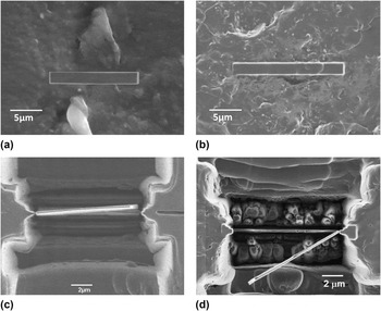
Focused ion beam (FIB) technology was used to prepare the TEM specimens for this work. The first step, which is also the most critical step in TEM specimen preparation by FIB, is to identify the sample location. In this work, both random locations and specific locations were selected, which are discussed in detail in Sec. III. The chosen sample location (length – 20 μm, width – 2 μm, depth – 0.5 μm) was coated by carbon deposition to protect it from the ion beam. Then, rough and fine milling was applied to make a lamella having a thickness of around 100 nm. After ion beam milling, the sample was tilted to cut loose the bottom of the lamellae. After cutting the right and left side of the lamellae, the lamella was separated from the trench. Then, the lamella was picked out from the trench using a micromanipulator under optical microscopy, and attached to a TEM film sample holder.
C. Initial assessment by 2D-TEM
Before 3D-TEM observation, samples were examined by 2D-TEM to check the CNTs density in the PA12 matrix, as well as the sample quality for 3D-TEM. Due to the small observation area of the TEM, several TEM samples were required to extract the bulk properties. This work was carried out with a JEOL JEM 2100F electron microscope (JEOL Ltd., Tokyo, Japan).
D. 3D-TEM tomography observation
3D-TEM tomography was carried out with a JEOL JEM 2100F electron microscope at the accelerating voltage of 200 kV. First, 2D-TEM images were collected by a CCD camera. With a 2° increment, a series of 2D projection images with tilt angles ranging from +60° to −60° were collected. When the sample was tilted to a different angle, there was sample shifting and focus change, therefore alignment was applied manually across the entire tilt angle range before data acquisition. In total, 61 2D-TEM projection images from the same sample area were taken. Due to the high TEM working voltage (200 kV), the PA12-CNT TEM samples experienced shrinkage during the process. Therefore, precise alignment was required before taking each image. Then, 3D reconstruction was carried out by computer with a Fourier transform reconstruction method to combine all of the 2D-TEM images. Reference Frank21,Reference Koster, Chen, Sedat and Agard26
III. RESULTS AND DISCUSSION
A. Sample location identification and preparation
For TEM observation, preparing high quality specimens is of great importance. FIB milling is a powerful method for preparing TEM specimens. The biggest advantage of using FIB is that site-specific TEM specimens can be prepared, which is very important for the current study. FIB is also independent of the nature of the materials, and can be applied to nearly any type of material, both hard and soft. As polymer composites normally contain two types of material, filler and matrix, FIB is therefore particularly suitable for composite materials. Furthermore, FIB is generally faster and more accurate than manual preparation methods. Reference Mayer, Giannuzzi, Kamino and Michael27 Therefore, in this work FIB milling was used to prepare the TEM specimens.
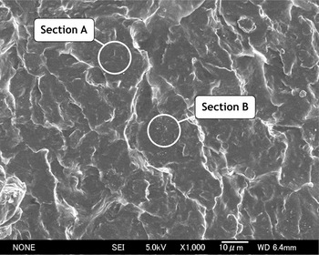
Identifying the TEM lamella location is also a very important step. The cross section of a laser-sintered PA12-CNT part is shown in Fig. 1. It can be seen that the cross section is uniform and no obvious CNTs are observed in most areas. However, in a few regions, some clustered small white spots are observed (section B in Fig. 1), which the authors identified as a possible CNT rich region. Therefore, TEM lamellae specimens were prepared in two locations, one was in a random region where no intensive white spots were observed (section A in Fig. 1), shown in Fig. 2(a); and the other was in a clustered white spots region (section B in Fig. 1), which is shown in Fig. 2(b). Figures 2(c) and 2(d) show the thin TEM samples cut loose by ion milling and ready to be lifted out. After ion milling, the lamella was lifted out using a micromanipulator, and transferred to a TEM sample holder.
Fractured cross section of a PA12-CNT laser-sintered part. Section A: random section without white spots cluster; Section B: section rich in white spots.

TEM sample prepared by FIB, (a) protective deposition at random area, (b) protective deposition at intensive white spots region, (c) thin TEM lamella sample prepared by ion milling at random region, (d) thin TEM lamella sample prepared by ion milling at intensive white spots region.

B. Initial assessment
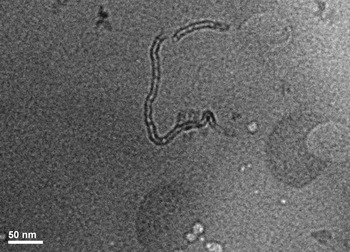
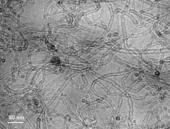
The TEM samples prepared in Fig. 2 were examined to check the density of the CNTs in the PA12 matrix before 3D-TEM observation. The 2D-TEM images of samples prepared from a random region and a rich white spots area are shown in Figs. 3 and 4, respectively. It can be seen that both images show good contrast between the PA12 matrix and the CNT fillers.
TEM image of a random region of PA12-CNT as prepared in Fig. 2(a).

TEM image of rich white spots region as prepared in Fig. 2(b).

In Fig. 3, which is the sample prepared from a random region, CNTs were observed, but only a few. In Fig. 4, which was the rich white spots region, intensive well-dispersed CNTs can be seen clearly throughout the TEM sample. This proved that the observed clustered white spots regions [Fig. 2(b)] were CNTs embedded in the PA12 matrix.
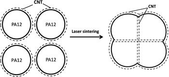
The different CNT densities between Figs. 3 and 4 could be explained by the method used to produce the PA12-CNT powders and also the mechanism by which the particles are consolidated in laser sintering. The PA12-CNT powder was prepared by coating CNTs on the surface of the PA12 particles. When processed by laser sintering, most of the PA12-CNT powder particles were only partially melted, with the surfaces melting to allow consolidation but the core of the particle remaining unmelted. Reference Bai, Goodridge, Hague, Song and Okamoto17,Reference Zarringhalam, Majewski and Hopkinson28 Therefore, most of the CNTs were distributed at the sintering borders rather than dispersed all over the nanocomposites matrix evenly. This is illustrated schematically in Fig. 5. Therefore, in most regions of the laser-sintered PA12-CNT part, there were only a few CNTs, as is seen in Fig. 3. On the other hand, in the sintering border region between PA12-CNT particles, intensive CNTs were expected, as shown in Fig. 4. The average particle size for PA12 was 57 μm, and thus, as the powder particles were only partially melted, the particle boundaries should be seen to be around 57 μm or less in the laser-sintered parts, depending on where the particle was sectioned. This is supported by Fig. 1.
Schematic explanation of laser sintering of CNTs coated PA12 nanocomposites, dash lines represent the CNTs.

C. 3D-TEM observation
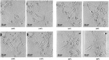
As most CNTs were located intensively in the white spots region (Fig. 1), the 3D-TEM observation was carried out with the sample prepared from this region. In total, 61 2D-TEM projection images from the same sample area were taken with tilt angles ranging from +60° to −60°. In Fig. 6, eight typical 2D-TEM images of the PA12-CNT laser-sintered specimens at various tilt angles are shown. Several CNTs can be observed clearly at each angle. A computer 3D reconstruction was then carried out based on these 2D tomography images.
2D-TEM images of a PA12-CNT laser-sintered part at various tilt angles.

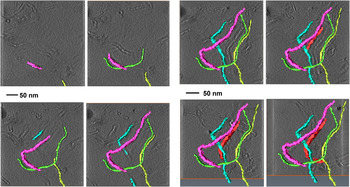
By combining all of the 2D-TEM images of the PA12-CNT laser-sintered specimen from −60° to 60°, 3D-TEM images were reconstructed, as shown in Fig. 7. Each color strand represents a single CNT. With the increase in the angle, the 3D nanosize structure of the CNTs distributed in the PA12 matrix was revealed gradually.
3D-TEM reconstruction process for a PA12-CNT laser-sintered specimen. Each color represents a single CNT.

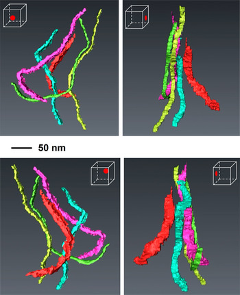
Following computer reconstruction, the 3D representations of the CNTs in a PA12-CNT laser-sintered part are shown in Fig. 8, where each color strand denotes a single CNT. These 3D images clearly show that CNTs remained agglomerate-free in the PA12 matrix after laser sintering, which is very important to achieve an enhancement in the mechanical properties of laser-sintered nanocomposite parts. It has previously been shown that the method to prepare the PA12-CNT powder allows the CNTs to be dispersed agglomerate-free on the surface of the powder. Reference Bai, Goodridge, Hague and Song16 3D-TEM results demonstrate that this remains the case within the sintered nanocomposite parts, indicating that the laser sintering process does not vary the dispersibility of the CNTs in the PA12 matrix. In our previous study, laser-sintered PA12-CNT nanocomposite parts showed enhanced flexural, impact, and tensile properties compared with neat PA12 parts. Reference Bai, Goodridge, Hague and Song16 The 3D-TEM results showed that the agglomerate-free CNTs were enriched in the powder boundary area (Fig. 5). As weak points and voids normally exist at the powder boundaries, enriched CNT areas would increase consolidation and decrease voids in the powder boundary area. A 4% increase in bulk density was observed through the addition of 0.1 wt.% multiwalled CNTs, with the reduced porosity likely to decrease crack initiation sites. Reference Bai, Goodridge, Hague and Song16 This may explain why such a large increase in mechanical properties was observed in our previous work. Reference Bai, Goodridge, Hague and Song16 It has however previously been reported that the lack of dispersion of the nanofiller and the presence of agglomerates has a significant negative effect on the mechanical properties of laser-sintered composites parts. Reference Athreya, Kalaitzidou and Das9 Therefore, the improvement of the PA12-CNT strength could also be contributed to the agglomerate-free CNTs dispersed in the laser-sintered parts.
3D representations of the CNTs in the PA12-CNT laser-sintered parts; each color represents a single CNT.

IV. CONCLUSIONS
In this study, 3D-TEM tomography was used for the first time to provide a nanostructural observation of CNTs in a laser-sintered PA12-CNT nanocomposite part. This work has shown that:
-
(i) FIB is a feasible and useful technique to prepare TEM specimens of PA12-based laser sintering parts.
-
(ii) According to TEM studies, different CNTs densities were observed in the laser-sintered PA12-CNT parts. It is likely that this is due to the method used to produce the PA12-CNT powders, which coated the CNTs on the surface of the PA12 powder particles, and also the mechanism by which the particles are consolidated in laser sintering.
-
(iii) 3D-TEM results revealed that the CNTs were agglomerate-free and enriched in the sintering border area of the laser-sintered PA12-CNT parts. This is likely to be contributing to the significant improvement in mechanical properties of the PA12-CNT laser-sintered parts reported previously.
-
(iv) This work demonstrated that it is possible to characterize the dispersion of CNTs in the laser-sintered PA12 parts via a 3D-TEM technique. 3D-TEM tomography could be a feasible way to reveal the 3D characterization of both the surface and the bulk of laser-sintered PNCs.
ACKNOWLEDGMENTS
We would like to thank EPSRC, UK and the Transmission Electron Microscopy station in the National Institute of Materials Science (NIMS), Japan for supporting this work. We would also like to acknowledge the GB Sasakawa Foundation for providing a travel bursary to J. Bai.