I. INTRODUCTION
In last few years, supercapacitors have received significant attention due to their rapid power transfer, high power density and high energy density, along with shorter charging time as compared to conventional storage devices. Reference Yu, Tetard, Zhai and Thomas1 Electrical double-layer (EDL) capacitance and pseudocapacitance follow two different energy storage mechanisms. Former arises from the accumulation of charges at the electrode/electrolyte interface, whereas latter is generated by Faradic redox reactions involving electrically conducting polymers or metal oxides as electrode materials. Reference Hellstern, Kitzler, Neuhaus, Kolaric, Bargende, Reuss and Wiedemann2–Reference Bao, Zang and Li4 Most widely used electrode material for supercapacitors includes transition metals, conducting polymers, and carbon materials with high surface area. However, these materials have some drawbacks, such as low specific capacitance of carbon material and poor cyclic ability of conducting polymers which limit their use as supercapacitor. Reference Chen, Bo and Lu5–Reference Villers, Jobin, Soucy, Cossement, Chahine, Breau and Bélanger8
Graphene, an allotrope of carbon with two-dimensional structure, was reported in 2004 Reference Novoselov, Geim, Morozov, Jiang, Katsnelson, Grigorieva, Dubonos and Firsov9 and is one of the most promising supercapacitor electrode material having high surface area, remarkable chemical stability, and superior electrical conductivity. It can be used as an ideal platform to build graphene based composites with metal, metal oxide, and conducting polymers for energy storage applications. Reference Mao, Hu and Liu10 It has acquired great importance due to its extraordinary physical, electrical, mechanical, optical, and structural properties. Reference Seong and Kim11–Reference Rashad, Pan, Asif and Tang14
Manganese oxide (MnO2) is the most widely used electrode material for redox reactions due to its natural abundance, low cost, environmental capability, and multiple reversible electrochemical reactions. Recently, researchers have used manganese oxide in companions with high conducting materials such as graphene as an electrode material for capacitive storage application. Reference Guo, Li, Zhang, Huo and Xu15–Reference Huang, Mi, Liu, Li, Zhao, Zhang, He and Zhang17
MnO2/graphene/nickel foam (NF) composite fabricated by a facile electrochemical deposition approach exhibited a specific capacitance of 476 F/g. Reference Zhao, Zhao, Tang, Wang, Xu and Li18 Researchers have tried various techniques, such as redox deposition, electrodeposition, microwave irradiation, and polymer assisted chemical reduction to synthesize graphene/MnO2 nanocomposite. Reference Hao, Zhong, Liao, Shu, Kang, Zou, He and Guo19–Reference Chen, Zhang, Geng, Li, Hong, Chen and Sun23
Manganese oxide deposited on NF–graphene by hydrothermal microwave irradiation technique, depicted a specific capacitance of 305 F/g at a current density of 1 A/g. Reference Bello, Fashedemi, Fabiane, Lekitima, Ozoemena and Manyala24 MnO2–graphene foam with controlled MnO2 particle shape showed a specific capacitance of 560 F/g at a current density of 0.2 A/g. Reference Dong, Wang, Wang, Song, Li, Wang, Chan-Park, Li and Chen25 Polyaniline/MnO2 composite synthesized by simultaneous oxidation route showed maximum specific capacitance of 320 F/g. Reference Zhang, Shu, Zhang, Chen, Zhao, Wang, Sun, Tang, Fang and Cao26 Hydrothermal deposition of MnO2 nanosheets by in situ redox reaction exhibited a high specific capacitance of 462 F/g at 0.5 A/g. Reference Li, Cao, Wang, Yang, Zhang, Ye, Cheng, Yin, Wang and Xu27
We used MnO2/PANI simultaneously with nickel foam graphene (NFG) in a unique and facile way to get binder free electrode for efficient supercapacitor. We synthesized a three-dimensional defect free graphene on NF by chemical vapor deposition (CVD) technique, with good porosity and high conductivity. We believe this work would prove a milestone toward the development of composite materials for electrochemical energy storage technology.
In this work, we present a simple and an efficient green approach to synthesize NFG/MnO2/PANI composite as an electrode for high-performance supercapacitor applications. The NFG/MnO2/PANI composite has a high electrochemical surface area and 3D porous interlinked network. This unique electrode structure not only boosts ion and electron exchange in electrochemical process but also serves as a 3D platform for combination and integration of MnO2/PANI on the NFG.
The composites (NFG/MnO2/PANI) display a very good electrochemical behavior with remarkable capacitance retention at high current density. Our result depicts that NFG provides a suitable platform for developing functional materials with enhanced electrochemical performance as an electrode.
II. EXPERIMENT
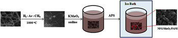
The experimental procedure is illustrated in Fig. 1. In the first step, graphene is synthesized on NF using CVD. NF (420 g/m2 in area density and 1.6 mm in thickness) is rinsed in acetone solution for an hour by ultrasonication to serves as a template for graphene growth. Reference Bello, Makgopa, Fabiane, Dodoo-Ahrin, Ozoemena and Manyala28 The NF is annealed at 800 °C in the presence of Ar and H2 for 20 min, to remove impurities present in Ni foam, before mixing CH4 gas at about 1000 °C. During growth stage, CH4, H2, and Ar gases with flow rates of 10, 200, and 300 sccm, respectively, are introduced in the quartz tube. During second step, 10 ml KMnO4 (0.02 M) and aniline (2.45 mM) solutions are prepared, sonicated for 10 min separately and then both solutions are mixed. Then, NFG is mixed in the solution and sonicated for 40–50 min. In last step, the solution containing graphene sample is kept in an ice bath and 10 ml (1 mmol) ammonium per sulfate solution is added slowly to convert aniline into polyaniline. The following equation illustrates the formation of PANI/MnO2 on NFG.
 $${\rm{KMnO}}_4 + {\rm{aniline}} \to {\rm{MnO}}_2 \cdot{n{\rm{H}}_2 {\rm{O}} + {\rm{PANI}}\quad {\rm{.}}$$
Schematic illustration for the formation process of NFG/MnO2/PANI composite.

The resulting solution is maintained in ice bath for 12 h, rinsed with de-ionized water and dried at 60 °C for 24 h. For comparison, NFG/MnO2 composite is also prepared with the same process.
A. Characterization
X-ray diffraction (XRD) analysis is carried out by Cu Kα (1.5406 Å) radiation. The surface morphology and microstructure of the composite are investigated by scanning electron microscope (SEM) operated at 10 kV. Raman spectroscopy is recorded with Renishaw inVia (Renishaw plc, Gloucestershire, UK) plus He–Ne laser, 632.8 nm, 10% laser power. The oxidation states are investigated by x-ray photoelectron spectroscopy (XPS) using Al Kα radiation.
CHI600D electrochemical workstation with three-electrode system (CH Instruments, Austin, Texas) is used for electrochemical measurements. The prepared NFG/MnO2/PANI composite directly serves as the working electrode. A platinum foil and saturated calomel electrode are used as the counter and reference electrodes, respectively. A 6 M KOH solution (aqueous) is used as an electrolyte. Cyclic voltametric range is kept from 0 to 0.4 V at different scan rates. Galvanostatic charge–discharge (CD) experiment is performed in range of 0–0.4 V with applied current density gradually increasing from 0.5 to 10 A/g. The electrochemical impedance spectroscopy (EIS) analysis is performed at AC 0.01 V and frequency range of 1 × 10⁵–1 × 10⁻² Hz.
III. RESULTS AND DISCUSSION
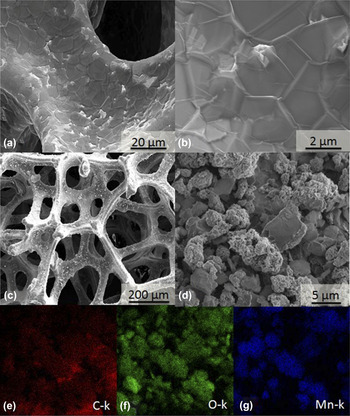
The SEM images of graphene on the NF template are shown in Figs. 2(a) and 2(b). The graphene grown by CVD on the template manifests identical three-dimensional (3D) porous network structure.
SEM micrographs of (a, b) NFG at different magnifications, (c, d) NFG coated with MnO2/PANI at different magnifications, (e–g) EDS mapping of (d)

From Fig. 2(b), it is evident that during the CVD synthesis process, graphene wrinkles and ripples appear due to the difference between thermal expansion coefficient of graphene and Ni. Reference Chae, Güneş, Kim, Kim, Han, Kim, Shin, Yoon, Choi and Park29 The mentioned conductive structure can be an excellent substrate to incorporate metal oxides for electrochemical applications. The morphologies of the NFG/MnO2/PANI composite are investigated and the results are shown in Figs. 2(c) and 2(d).
The structure is further investigated by energy dispersion spectroscopy mapping (EDS), as shown in Fig. 2(d). Elemental maps of carbon, Oxygen and Mn are shown in Figs. 2(e)–2(g), respectively.
There are two kinds of materials in Fig. 2(d) (i) showing PANI, (ii) agglomeration of MnO2 particles (and/or PANI), as confirmed by EDS mapping shown in Figs. 2(e)–2(g). MnO2/PANI on NFG shows compact granular morphology. This type of structure allows shorter ion diffusion path which can enhance the rate capability and specific capacitance. Reference Teng, Santhanagopalan, Wang and Meng30
MnO2/PANI is intermixed and uniformly deposited on the surface of NFG. It not only reduces particle size but also enhances surface area. Graphene acts as a bridge between them and forms an excellent connection on intermolecular level which is beneficial for electron transfer. The resulted nanostructure provides large specific surface area for interaction between the composite and electrolyte. In supercapacitors, such a unique structure is useful when ions are adsorbed onto the surface of the samples, thus leading improved capacitance and excellent electrode electrolyte interface for ions exchange.
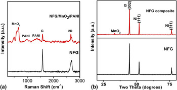
Raman spectrum of the graphene on the NF and composite is shown in Fig. 3(a). The graphene on NF exhibits two major peaks at 1581 and 2658 cm−1, corresponding to the G and 2D modes in graphene. The intensity of the 2D, I 2D/I G ratio and full width half maximum indicates that the graphene sheets consist of mostly few layers. The absence of the D-peak at 1350 cm−1 shows the good quality of graphene sheet and has a very low defect density. Reference Ferrari31
(a) Raman spectra of NFG and NFG/MnO2/PANI composite (b) XRD patterns of NFG and NFG/MnO2/PANI composite.

Raman spectra of composite show a broad band around 649.9 cm−1 originating from MnO2 nanostructures. This band belongs to the Ag mode arising from the breathing vibrations of MnO6 octahedral double chain. This band can be assigned to the Mn–O stretching vibration mode in the basal plane of MnO6 octahedral chains of MnO2. Reference Gao, Fjellvåg and Norby32 The peaks at 986.2, 1367.7 cm−1 for the NFG/MnO2/PANI composite may correspond to imine (PANI) deformation, in plane C–H bending of quinoid, C=N stretching, respectively. Reference Wang, Hao, Yang, Lu and Wang33
The good contact between MnO2/PANI on the intermolecular level formed due to simultaneous–oxidation process can facilitate the electron transfer. Reference Shu, Zhang, He, Meng, Chen, Zhang and Zheng34 It may be synergistic effect caused by PANI or interaction of PANI and MnO2 on the surface of NFG.
The crystallographic structure of the NFG and composite is studied using XRD as shown in Fig. 3(b). The low diffraction peak of the MnO2 on NFG is a result of its small average crystallite domain size, Reference Bello, Fashedemi, Fabiane, Lekitima, Ozoemena and Manyala24 while PANI appeared to be an amorphous.
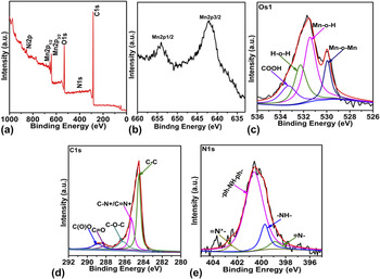
For complete understanding of the surface characteristics of the sample, the NFG/MnO2/PANI composite is analyzed further using XPS. Figure 4(a) shows wide scan XPS spectrums, which confirm the presence of Mn2p, N1s, C1s, and O1s in the composite, indicating the existence of PANI and manganese oxide components. Figure 4(b) Mn2p XPS spectrum presents the core level Mn2p1/2 and Mn2p3/2 spin–orbits peaks of MnO2, with binding energies of 653.8 and 642.2 eV, respectively, confirming the presence of MnO2 in the composite. Reference Wu, Ren, Wang, Li, Liu and Cheng35 The spin-energy separation of 11.6 eV is also observed between the two peaks, which is in good agreement with the published data for Mn2p1/2 and Mn2p3/2 in MnO2. Reference Winter and Brodd36 The O1s core level spectrum is also reflecting the existence of Mn oxides, as shown in Fig. 4(c). The spectrum can be deconvoluted into four components, which are related to Mn–O–Mn (530.0 eV), Mn–O–H (531.4 eV), COOH (533.3 eV), and H–O–H (532.27 eV). Reference Sharma, Rastogi and Desu37–Reference Sun, Liu, Lau, Chen and Gu39 The COOH bonds are remnants of the oxides functional groups of the graphene. The C1s spectrum of NFG/MnO2/PANI shown in Fig. 4(d) can be deconvoluted into five peak components at the binding energies at 284.5, 286.2, 285.2, 288, and 289.0 eV, corresponding to C–C, C–O, C–N+/C=N+, C=O, and CO(O) species, respectively. Reference Xiong, Hu, Fan, Zhang, Zhu and Wang40–Reference Morozan, Jegou, Jousselme and Palacin42 However, C1s core level spectrum peak at 284.5 eV also represents the sp 2 carbon network by C–C bonds in graphene and C–C bonds in the benzenoid ring, showing a combination of imine and amine sites via shake-up process. Reference Monkman, Stevens and Bloor43 An additional peak around 285.2 eV assigned to C–N+/C=N+ can be observed, confirming the presence of PANI in NFG/MnO2/PANI composite. As shown in Fig. 4(e), nitrogen atoms were found within four different forms. The peaks are located at 398.8, 399.5, 401, and 402.5 eV respectively, which can be ascribed to imine like structure =N–, amine like nitrogen atom –NH–, –ph–NH–ph–, and protonated imine =N+–, respectively. Reference Sun, Liu, Lau, Chen and Gu39 PANI have a general formula [(–B–NH–B–NH–) y (–B–N–Q–N–)1−y ] X in which B and Q denote the C6H4 rings in the benzenoide and quinoid forms, respectively. The intrinsic oxidation state of PANI can vary from fully oxidized pernigraniline (PNA, y = 0), through 50% oxidized emeraldine (Em, y = 0.5), the protoemeraldine base (PEM, y = 0.75), to fully reduced leucoemeraldine (LM, y = 1). Reference Angelopoulos, Asturias, Ermer, Ray, Scherr, Macdiarmid, Akhtar, Kiss and Epstein44,Reference MacDiarmid, Yang, Huang and Humphrey45 PANI achieves its highly conductive state either through protonation of the imine nitrogens (–N–) in its emeraldine state or through the oxidation of the amine nitrogens (–NH–) in its fully reduced leucoemeraldine state. Reference Rodrigues, Muraro, Garcia, Souza, Abbate, Schreiner and Gomes46 PANI in the composite is half oxidation and half reduction status, Reference Zhang, Shu, Zhang, Chen, Zhao, Wang, Sun, Tang, Fang and Cao26 as it is also verified by electrochemical test. Therefore, PANI plays an excellent role to enhance conductivity, which is beneficial to improve the electrochemical property of the NFG/MnO2/PANI composite.
(a) Survey (b) Mn2p (c) O1s (d) C1s and (e) N1s XPS spectrum for NFG/MnO2/PANI composite.

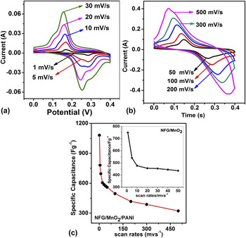
Figures 5(a) and 5(b) shows the cyclic voltammetry curves of the NFG/MnO2/PANI composite electrode at scan rates of 1, 5, 10, 20, 30, 50, 100, 200, 300, and 500 mV/s, with potential windows ranging from 0 to 0.4 V, in 6 M KOH aqueous solution. The quasi-rectangular shapes of these curves demonstrating the ideal EDL capacitance behavior and fast charging/discharging process characteristic. In each curve, there are two redox peaks which can be ascribed to the redox transitions, Reference Hummers and Offeman47 as shown Fig. 5(a). These redox reactions are due to PANI film, which contribute to the pseudocapacitor due by changing the leucoemeraldine/emeraldine and emeraldine/pernigraniline states. Reference Wang, Yu, Hwang, Ho and Chen48 The redox peaks are symmetric which indicates that the sample electrode has good reversibility in a KOH solution.
(a) CV curves of NFG/MnO2/PANI at scan rates of 1–30 mV/s. (b) CV curves of NFG/MnO2/PANI at scan rates of 1–500 mV/s. (c) Specific capacitance of the composites verses scan rate with inset of NFG/MnO2.

It is also observed that the specific capacitance decreases from 1081 to 323 F/g with the increase of potential scan rate from 1 to 500 mV/s as shown in Fig. 5(b). The reason is that at high scan rates, electrolyte ions can only reach the outer surface of the electrode and the active material, thus the deep pores cannot actively contribute to the pseudocapacitance. Reference Jang, Machida, Kim and Naoi49
Figure 5(c) shows the calculated specific capacitance using the formula
 $C_{\rm{s}} = {1 \over {2vm\Delta V}}\mathop \int \nolimits I\,{\rm{d}}v$
, where C
s is the specific capacitance,
 $\int {I \,{\rm{d}}v}$
is the integrated area of the CV curve, m is the mass of active material,
 $\Delta V$
is the potential range, and v is the scan rate. At the scan rate of 1 mV/s, the specific capacitance of the NFG/MnO2/PANI composite can achieve 1081 F/g, while NFG/MnO2 composite is 750 F/g. Therefore, in the NFG/MnO2/PANI composite the capacitance is higher than NFG/MnO2 composite, because the electrochemical accessible surface area is remarkably increased with PANI. The larger specific capacitance of NFG/MnO2/PANI composite may be caused by the following reasons:
At first, during the in situ chemical polymerization process, good contact in the intermolecule level between NFG/MnO2/PANI is formed. Second, preventing the composite particles from agglomerating, due to which large specific surface area and high electrochemical utilization of the composite material are realized. This can be justified that PANI may involve partially Faradaic pseudocapacitance in the composite. Reference Zhou, Cai and Zhou50
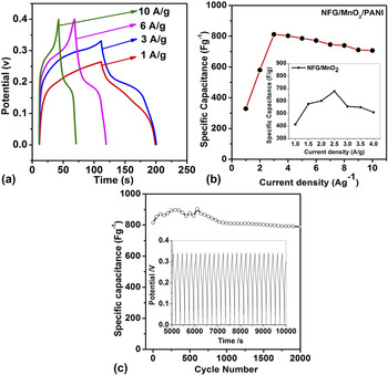
Figures 6(a)–6(c) show the galvanostatic CD curves for the NFG/MnO2/PANI electrode, at different current densities. The anodic charging and cathodic discharging curves are nearly symmetric, demonstrating ideal capacitive properties in the potential range. Besides, IR drop is the electrical potential difference between the two ends of a conducting phase during a current flow. Reference Yuan, Su, Gao and Zhang51 In the CD curves, IR drop can be observed [Fig. 6(a)]. The CD curve of NFG/MnO2/PANI composite shows a less IR drop. This further confirms the lower contact resistance in the composite.
(a) CD curve of NFG/MnO2/PANI electrode at different current densities. (b) Specific capacitance of the composites versus current density with inset NFG/MnO2. (c) Specific capacitance versus cyclic number.

The maximum specific capacitance of NFG/MnO2/PANI calculated from the CD curves is 815 F/g at the current density of 3 A/g, using the formula
 ${C_{\rm{s}}} = {{I \times \Delta t} \over {m \times \Delta V}}$
, where C
s is the specific capacitance (in F/g), I is the charge/discharge current (in A), ∆t is the discharge time (in s), and ΔV is the potential difference, and m is the mass of active material within the electrode. At the current density of 3 A/g, the specific capacitance of the NFG/MnO2/PANI composite can achieve 815 F/g, while NFG/MnO2 composite is 650 F/g. Therefore, in the NFG/MnO2/PANI composite, the capacitance is higher than NFG/MnO2 composite, as shown in Fig. 6(b). Thus, NFG/MnO2/PANI composite is more competitive than reference NFG/MnO2 composite.
The stability of NFG/MnO2/PANI electrode is investigated by galvanostatic CD curves for many cycles. The galvanostatic CD is recorded for 2000 cycles at the current density of 3 A/g in a 6 M KOH solution. The specific capacitance of the NFG/MnO2/PANI electrode material increases with the increase of the cycle number up to first 1000 cycles. Afterward, the capacitance slightly decays and finally retains 99% of the initial value after 2000 cycles, indicating an excellent cycle stability of the electrode, as shown in Fig. 6(c). The excellent cycle stability may be attributed to the cohesive intermolecular contact between NFG/MnO2/PANI particles, which prevents the dissolution of MnO2. The capacitance attenuation can be attributed to two reasons; (i) a little dissolution of MnO2 is inevitable, (ii) for many repeated redox processes, the redox sites in the PANI are insufficiently stable, which is perhaps the result of swelling and shrinking of PANI under aqueous environment leading to the degradation of PANI during the long term cycling. Reference Sun, Liu, Lau, Chen and Gu39 At the end, both the specific capacitance (1081 F/g) and cycle stability (retention of 99% over 2000 continuous cycles) of our composite displays many advantages comparing to the reported literature. Reference Zhou, Cai and Zhou50–Reference Zhang, Zhang and Yang54
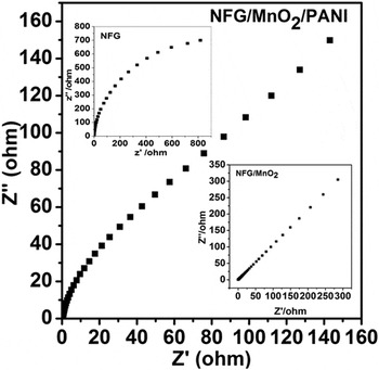
The EIS (Nyquist) plot of NFG/MnO2/PANI is shown in Fig. 7, with insets of NFG and NFG/MnO2. This indicates that the composition reflects reduce the internal resistance of graphene and MnO2/PANI; therefore, indicating better capacitive behavior. The Nyquist plot of NFG/MnO2/PANI shows the ideal behavior of the electrode material.
EIS plot of NFG/MnO2/PANI with insets of NFG and NFG/MnO2.

IV. CONCLUSIONS
NFG/MnO2/PANI composite is prepared by a simple route. In this method, PANI and MnO2 grow on the surface of the NFG and good contact in the intermolecule level is established. The maximum specific capacitance of the composite electrode is measured to be 1081 F/g at the scan rate of 1 mV/s and 815 F/g at the current density of 3 mA/g. The specific capacitance of the composite electrode retains approximately 99% of the initial value after 2000 cycles, indicating good cycle stability of the composite. The excellent capacitive behavior of the NFG/MnO2/PANI composite is due to the good contact in the intermolecular level between PANI and MnO2 formed on NFG surface during the preparation, and the high electrochemical utilization of the composite material by preventing the composite particles from agglomerating.
ACKNOWLEDGMENTS
This work was supported by the National Natural Science Foundation of China (Nos. 11274055, 61137005) and the Program for Liaoning Excellent Talents in University.