I. INTRODUCTION
Porous fiber/wire metals with metallic fibers/wires as raw materials refer to a metallic body with through-pores integrated in their structures. Compared with other porous materials, porous fiber/wire metals have many favorable characteristics. For example, the mechanical strength, stiffness, and ability to impact energy absorption are much higher than those of polymer foams. They maintain their mechanical properties at wide working temperature ranges and keep more stable performance in harsh environments compared to polymer foams. Besides, they are thermally and electrically conductive and slow aging than polymer foams. As opposed to ceramics, they have a good ability to deform plastically and load in the static or dynamic condition. They can be fabricated by a simple manufacturing process and achieve the integration of high surface area, perfect permeability, and the above advantages. Reference Lefebvre, Banhart and Dunand1,Reference Kang2 Due to their comprehensive properties, porous fiber/wire metals are widely used in the engineering field. There has been considerable interest in the production and mechanical properties of porous fiber/wire metals.
Metallic fibers/wires have some merits as the raw materials used for fabricating porous fiber/wire metals. Mass production of fibers/wires is a mature technology. Most of the metals including tungsten and zirconium can be made into fibers/wires. A mother material with high strength and low defects can be easily obtained from wires, such as stainless steel wires, carbon steel wires, aluminum alloy wires, copper fibers, FeCrAl fibers, and titanium fibers. Porous fiber/wire metals should be produced at low cost. Besides, the wires are easy to handle and form into a shape during fabrication. In fact, metallic wires are often twisted into ropes or weaved into meshes like screen mesh and mosquito nets using traditional weaving technologies. Reference Kang2–Reference Kang6
Porous fiber/wire metals have been made of short fibers/wires and long fibers/wires. Several mainstream methods for manufacturing fibers/wires have been developed like bundle drawing, melt spinning, and cutting. Reference Yuan, Tang, Yang, Liu and Wan7 Bundle drawing is mainly used for the continuous production of fibers/wires. Short fibers/wires are fabricated by the melt spinning or cutting method. Zhou Reference Zhou, Tang, Wan, Lu, Chi and Pan8 has developed a multitool cutting method to obtain copper fibers. To date, according to the length and assembling of fibers/wires, the study on porous fiber/wire metals mainly includes the following types. Metal fiber/wire felts belong to the first category. They are based on the short metal fibers/wires as raw materials. Stochastic metallic short fibers/wires are put into different packing chambers of mold pressing equipment and then sintered at high temperature to fabricate metal fiber/wire felts. There have been several previous experimental studies on metal fiber/wire felts that are made of Cu, Reference Zhou, Tang, Pan, Wei and Xiang9 304, Reference Tan and Clyne10 446, Reference Markaki, Gergely, Cockburn and Clyne11 and 316L Reference Liu, He and Wu12,Reference Qiao, Xi, Tang, Wang and Zhu13 stainless steel fibers/wires, steel, Reference Liu, He and Wu14,Reference Liu, He and Wu15 and Ti. Reference Liu, Tan, Wu and He16 Entangled materials are the second category. They are made of a loose clew- or coil-spring-like steel wire bundle Reference Liu, He and Wu14,Reference Tan, Liu, Du, Wu and He17 with non-sintered or sintered processing after compacting in a special mold. The above two kinds of porous fiber/wire metals present an irregularly three-dimensional interconnected pore structure. A series of wire-woven metals with a periodic pore structure have been developed since 2006, such as wire-woven bulk Kagome (WBK), wire-woven bulk diamond (WBD), and wire-woven bulk cross (WBC). Reference Lee, Lee, Hur and Kang3,Reference Lee, Yoon, Han, Suh and Kang4,Reference Lee, Ko, Song and Kang18 These studies mainly focused on the mechanical behavior like tension, compression, and torsion. Only Liu Reference Liu, He and Wu15 has investigated the impact behavior of the entangled steel wire material (EWM) by the Charpy impact test. Obviously, the impact property is also one of the mechanical properties, which is a synthetic representation on plasticity and strength. As an important means to test dynamic mechanical properties under a high strain state, the Charpy impact test is used most widely for the evaluation of absorbed energy that is a measure of a given material’s toughness. Reference Liu, He and Wu15 Besides, the Charpy impact testing method is low cost and little constraints on specimens.
The present work mainly involves the impact behavior of a novel stainless steel porous twisted wire material (PTWM) by the Charpy impact test. Pore distribution characteristics of the PTWMs were also measured by a capillary flow porometer. The relationship between impact toughness and wire diameter and porosity and pore morphology is investigated. The impact behavior and its failure mechanisms are analyzed on the basis of experimental observation.
II. EXPERIMENTAL PROCEDURES
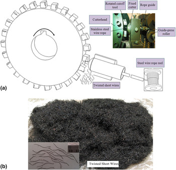
Stainless steel PTWMs were made of twisted short wires and produced by compaction followed by vacuum high-temperature solid-phase sintering. The twisted short wires with a diameter of 160 or 90 μm were fabricated by using a self-developed rotary multicutter tool to cut stainless steel wire ropes into segments with lengths ranging from 10 to 15 mm, as shown in Fig. 1(a). Detailed processing refers to our previous work. Reference Wu, Zhou, Duan and Xiao19 The twisted short wires are shown in Fig. 1(b). Subsequently, a specified mass of twisted short wires were put randomly into a specially designed mold that was detailed in our previous work. Reference Wu, Zhou, Duan and Xiao19 The semifinished PTWMs with different properties or various shapes can be obtained by altering the mass of wires or the shape of the packing chamber under a certain downstroke of fast oil hydraulic press. Then the compacted preforms were sintered in a vacuum furnace (the vacuum degree was approximately 1 × 10⁻² Pa). The temperature rise rate was controlled at 10 °C/min when the temperature was below 800 °C, and it was reduced to 6 °C/min when the temperature was above 800 °C. The PTWMs were finally treated at 1330 °C for 1.5 h.
Schematic depiction and in situ photos of rotary multicutter cutting off steel wire ropes. (a) The process of making the short wires and (b) twisted short wires.

Since the PTWMs have regular geometry shapes, the average porosity was calculated by using the quality-volume method that was formulated as
 $$P\left( \% \right) = \left( {1 - {M \mathord{\left/ {\vphantom {M {\rho V}}} \right. \kern-\nulldelimiterspace} {\rho V}}} \right) \times 100\quad ,$$
where P is the average porosity of stainless steel PTWMs, M is the mass of the porous material (g), V is the volume of the porous sample (cm3), and ρ is the density of the solid 304 stainless steel (g/cm3).
The microstructures of the stainless steel PTWMs were observed by a Hitachi S-3700N scanning electron microscope (SEM; Hitachi Ltd., Tokyo, Japan). Their pore distribution characteristics were measured by a capillary flow porometer (PSDA-20, GaoQ Functional Materials Co., Ltd., Nanjing, China) based on the liquid extrusion technique. Reference Yuan, Tang, Yang, Liu and Wan7,Reference Jean and Gupta20 The prismatic samples 55 × 10 × 10 mm3 for impact testing were prepared with a wire cutting machine. Following GB 5318-85, samples were tested in a pendulum impact testing machine (ZBC2302-2, Shenzhen Suns Co. Ltd., Shenzhen, China) at room temperature. The impact velocity was 5.2 m/s. The preelevation was 150°. Before testing, samples were placed upon two anvils with a span of 40 mm. The values of impact absorbing energy (A k) for each sample were directly displayed from the liquid-crystal monitor of the Charpy impact testing machine. The impact toughness αk of the PTWMs can be calculated by the following formula:
 $${\alpha _{\rm{k}}} = {{{A_{\rm{k}}}} \mathord{\left/ {\vphantom {{{A_{\rm{k}}}} F}} \right. \kern-\nulldelimiterspace} F}\quad ,$$
where A k is the impact absorbing energy (J), F is the cross section at the breakdown (cm2), and αk is the impact toughness, J/cm2.
III. RESULTS AND DISCUSSION
A. Typical porous structure of the PTWM
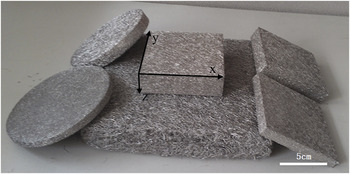
Figure 2 shows the appearance of the as-prepared PTWM samples with different specified shapes and properties. The porosities of PTWMs varied from 40 to 90%, depending on the different weights of twisted short wires. The entangled wires were distributed desultorily in the packing chamber of the specified mold. The pressurization resulted in a stochastic reticulated structure with many intercrossed conjunctive regions between the twisted wires. In the sintering process, metallurgical bonding is produced between the intersecting twisted wires. The PTWMs with a spatial composite intertexture pore structure can be clearly shown by further observation under a microscope.
The sintered PTWMs with different properties and shapes.

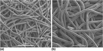
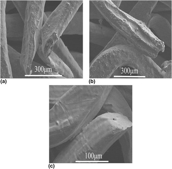
Figures 3(a) and 3(b) show morphologies with a SEM on the as-prepared PTWMs in the in-plane (x–y plane) and through-thickness (x–z plane) directions, respectively. These pores are in an interconnected open-pore microstructure with a variety of shapes and sizes. From the through-thickness directions [Fig. 3(b)], it can be seen that most of the twisted wires are intertwined and interembedded to form pore skeletons. As can be seen in Figs. 2 and 3, the pore structures of the PTWMs are more complex and irregular than those of cellular metals and foam metals and different from the spatial reticulated structure fabricated by straight fibers Reference Liu, He and Wu12,Reference Qiao, Xi, Tang, Wang and Zhu13,Reference Tang, Tang, Zhou, Lu and Qu21 and the structures of entangled materials. Reference Liu, He and Wu14,Reference Tan, Liu, Du, Wu and He17,Reference Lee, Ko, Song and Kang18,Reference Tan and He22 Figure 4 shows that there are diverse forms of sintering joints in the pore structure of the PTWMs.

SEM images of sintering joints between twisted short wires in the PTWMs. (a) Head connects with head (×190), (b) head connects with body (×160), and (c) body connects with body (×500).

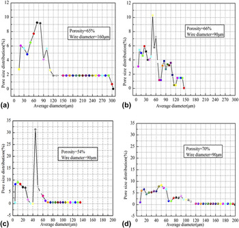
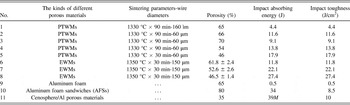
Table I summarizes all the pore sizes, pore distribution, and porosities of PTWMs. The pore sizes are of equivalent diameters. With similar porosities, the maximum pore size (303 μm), the minimum pore size (14 μm), and the average pore size (91 μm) with a diameter of 160 μm are higher than those of 90 μm by about a factor of 2. That is because the PTWMs with fine wires contain more twisted wires per unit volume under the same porosity. The average pore size increases from 48 to 60 μm with increasing porosity from 54 to 70%. Although the minimum pore size shows the same change tendency, the change is small. The maximum pore size with 66% porosity is about 7% larger than that with 54% porosity, and the maximum pore size is enlarged by about 38% with the increase of porosity from 66 to 70%. This nonlinear phenomenon suggests that a small change of the porosity may bring a great difference in the pore size.
Summary of the porous structures of PTWMs.

Figure 5 shows the pore average diameter distribution of the PTWMs with different wire diameters and porosities. From the curves, the PTWMs possess irregular pores and the pore sizes are diverse. The pore diameter has a wide and multiple-peak distribution. There are both small- and large-pore areas that are considerably presented in the PTWMs. The pores of the PTWMs with a diameter of 160 μm (65% porosity) are in the range of about 14–303 μm [Fig. 4(a)], in which 140–303 μm pores occupy 30%. But those of 90 μm (67% porosity) are only in the scope of about 6–144 μm [Fig. 4(b)]. This phenomenon hints that the wire diameter has a large effect on the pore size of the PTWMs. Under the same porosity, the finer the twisted wire, the narrower the pore distributes. As shown in Figs. 5(a) and 5(b), both the distributions show that the material has an evident multiple-peak distribution.
Pore size distributions of the PTWMs with (a) 160 μm wire diameter and 65% porosity, (b) 90 μm wire diameter and 66% porosity, (c) 90 μm wire diameter and 54% porosity, and (d) 90 μm wire diameter and 70% porosity.

Figures 5(b)–5(d) show the average pore diameter distribution of the PTWM with 66, 54, and 70% porosities that all were made of the twisted wires with 90 μm in diameter. The pores of the PTWM with 70, 66, and 54% porosities are in the range of about 7–200 μm, 6–144 μm, and 4–135 μm, respectively. The pores smaller than 100 μm of the previous corresponding porosities are about 87.6%, 89.8% and 93.6%, respectively. With the decrease of the porosities, the pore sizes become smaller and their distributions become convergent. That is because the twisted wires become more flexuous and easier to close up with decreasing porosities.
Liu Reference Liu, He and Wu15 described the pore distributions of the entangled wire materials with a diameter of 150 μm. A large span of the sizes in the as-prepared samples with 61.8% porosity exists, in which 45–300 μm pores occupy 67.0% and 300–850 μm pores occupy 33%. Reference Liu, He and Wu15 In contrast, as shown in Fig. 4(a), the PTWM with a diameter of 160 μm shows that 45–300 μm pores occupy 84.5% and its maximum pore size is 303 μm. The PTWM has a narrow distribution of pore diameter. The above obvious difference between these two porous sintered materials can be ascribed to their different fabricating methods and porous structure.
B. Charpy impact behavior of the PTWMs
Table II summarizes the results of the Charpy impact test for the PTWMs. According to the size of the specimen, the cross section of each specimen is 1 cm2. Based on a value of impact absorbing energy, impact toughness can be calculated by formula (2). The impact toughness of the PTWM (65% porosity) with a diameter of 160 μm is 4.4 J/cm2 and that of 90 μm (66% porosity) is 11.6 J/cm2. The impact toughness of the latter is about 2.6 times than that of the former. With similar porosities, by decreasing the twisted wire diameters from 160 to 90 μm, the pores distribution interval decreases from 14–303 to 6–144 μm. So the PTWMs with fine wires contain more twisted wires per unit volume and have a more compact pore structure, which leads to stronger impact resistance capacity. With 70%, 66%, 54%, and 46% porosities, the PTWMs have 9.1, 11.6, 13.8, and 17.9 J/cm2 impact toughness, respectively. Thus it can be seen that the lower the porosity, the higher the impact toughness. The impact toughness depends much on the porosity and increase with decreasing porosity.
A comparison between the PTWMs and other porous materials for Charpy impact properties.

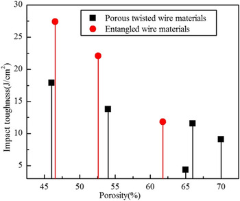
To provide a reference for comparison, the results of the Charpy impact test for a previous study on EWMs, Reference Liu, He and Wu15 aluminum foams, Reference Zhang, Zu, Yao and Liu23 and any other porous materials Reference Zu, Liu, Li and Sun24–Reference Kiser, He and Zok28 are also presented in Table II. The entangled wire materials with lower porosities have stronger impact resistance capacity. This general trend is consistent with the results of PTWMs. The impact toughness of the PTWM with 46% porosity is 17.9 J/cm2 and the EWMs with 46.5 ± 1.4% porosity have an average of 27.4 J/cm2. Reference Liu, He and Wu15 The wire diameters of the PTWM and the EWM are 90 μm and 150 μm, respectively. Under the similar porosity, the latter impact toughness increases by 50% over that of the former. The change in trend that the finer the wire diameter, the larger the impact toughness has not happened. That is because the EWMs exhibit a slot structure along the twisted and crossed wires, which is different from the pore structure of the PTWMs. The impact toughness of the EWMs with 52.6 ± 2.6% and 61.8 ± 2.4% porosities also increase by 60 and 1.7% over that of the PTWMs with 54 and 66% porosities, respectively. In general, the EWMs have a good resistance to impact relative to PTWMs. Although these two materials are prepared by stainless steel wires, there is a distinct difference between these two materials: the EWM is prepared by a bunch of long wires, where a single wire is intact and the length of the wires are 30 cm; the PTWM is prepared by twisted short wires, where a single wire looks like a fiber and the length of the wires is ranged from 10 to 15 mm. Obviously, subject to the size of original materials, the shapes of EWMs are only a big block or cylinder, while the shapes of the PTWMs are various, which can be seen in Fig. 2, and any other shapes like cushions and rings can be seen in Fig. S1.
The pore morphology also has obvious influence on the impact toughness. The impact toughness of aluminum foams with 65% porosity is less than 0.5 J/cm2, which is considerably below the impact toughness of the PTWMs and the EWMs. The aluminum foam sandwich (AFS) could obviously improve the impact performance of aluminum foams. From Table II, the impact toughness of the AFS with metallic bonding between the face panel and foam core is 8.5 J/cm2 and this value is about 18 times than the single aluminum foam. But the impact performance of the AFS is strongly depending on the bonding formed between the face sheets and foam core. The impact toughness of the AFS with adhesive bonding between the face sheet and foam core is only 1.5 J/cm2. The PTWMs have a good resistance to impact relative to the aluminum foam and AFS.
The cenosphere/Al porous material is a new type of functional material and belongs to metallic hollow spheres. The impact energy absorption properties of the cenosphere/Al porous materials is tested by using Hopkinson pressure bars and the value is 39 J/m3, much higher than that of common aluminum foams. The impact toughness of cenosphere/Al porous material is about 10 J/cm2 and this value is slightly lower than the PTWMs, but the porosity of cenosphere/Al porous material is 35%, and that is considerably lower than the PTWMs. The deformability of the low porosity materials is inferior to that of the high porosity materials. The mechanical properties of the high porosity cenosphere/Al porous material need to be improved.
It can be seen that the processing methods and wire/fiber properties exercise a great influence on the impact toughness. The above discussion reveals that the impact toughness has much more to do with wire diameters, porosities, pore morphology, processing methods, and wire/fiber properties. Figure 6 shows the impact toughness of the PTWMs and the EWMs with different porosities.
Impact toughness of the PTWMs with different porosities, and entangled wire materials are also shown in the plot for comparison.

As new kinds of functional materials, the porosity is ranged from 30 to 70%, the shapes are various as you want, and the impact performance is superior to the aluminum foams (include the AFS), metallic hollow spheres, and any other metallic porous materials. The PTWMs are of low cost and have unique advantages in impact energy absorption and improve the safety of automobiles.
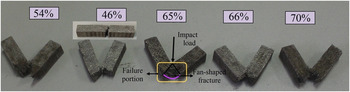
Figure 7 shows the postfailure macrograph of the PTWMs with different porosities or wire diameters in impact condition. All of the PTWMs were not completely fractured except the PTWM with 46% porosity. Figure 7 shows the complete fracture path of the PTWM with 46% porosity nearly parallel to the direction of the impact load. Its impact failure may follow the brittle mode. The PTWMs with 54, 65, 66, and 70% porosities exhibit a fan-shaped failure path, as shown in Fig. 7. Pore skeletons are impacted by a pendulum bend or fracture, which make the pore structure fluffy. With increasing porosity, the pore structure of the failure portion becomes increasingly fluffy, as shown in Fig. 7. The failure profiles all present very complex and irregular expanding paths. The angles between the failure paths and the impact loading direction are random. In this case, the PTWMs exhibit the plastic failure mode (the fracture path should present an angle of about 45° with the direction of impact load) but do not follow this rule fully. So the impact failure mode of the PTWMs cannot be simply regarded as a typical brittle fracture mode or a typical ductile fracture mode. The PTWMs present random failure paths and irregular fracture appearance, which demonstrates a mixed ductile–brittle failure mechanism. The process of impact failure may be summed up as follows: at the beginning of the Charpy impact, the local framework unit primarily produces plastic bending deformation in the scope of pendulum impact. Many pore skeletons are elongated, which gradually grow longer outward from the impact-load location. Further deformation leads to the breakage of pore skeletons. Pore skeletons mainly bend near the impact-load location and fracture far away from the impact-load location. Macroscopically, the impact deformation processes of the PTWMs can be seen as the processes from crack initiation to crack propagation and final failure. During the impact process, plastic bending, elongating, and fracture of pore skeletons contribute to the total absorbing energy of the specimens.
Postfailure macrograph of the PTWMs with different porosities in impact condition.

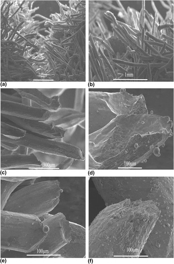
SEM micrographs of failure samples of the PTWMs in impact condition are shown in Fig. 8. Figures 8(a) and 8(b) show low magnification micrographs of the failure portion. Most wires within the scope of the failure portion are broken. Figures 8(c)–8(f) show high magnification fracture micrographs of pore skeletons in impact condition, which present detailed fracture morphologies of the broken wires. Figure 8(c) shows that the broken wires mainly exhibit wedge-shaped fractures and have different fracture morphologies. For example, Fig. 8(d) presents pits that may be attributed to the avulsion of sintering points [Fig. 4(c)]. There are obvious traces of tearing. Necking and dimple fracture occur, as shown in Fig. 8(e). Figure 8(f) shows the wedge-shaped fracture. These indicate that ductile rupture happens during the fracture process. In the macroscopic view, the PTWMs have a mixed ductile–brittle failure mechanism, but the impact failure process from the microscopic view mainly shows the ductile fracture. Therefore, the energy-absorbing capacity of the PTWMs is due to its deformation and failure mechanisms in impact condition, such as pore skeletons’ bending, rotating, moving, elongating, and fracture, as well as avulsion of sintering points.
SEM micrographs of failure samples in impact condition. (a and b) Low magnification micrographs and (c–f) high magnification micrographs.

IV. CONCLUSIONS
-
(1) A new type of the PTWM with a spatial composite intertexture structure has been produced by the vacuum high-temperature solid-phase sintering of twisted short wires. The twisted short wires are fabricated using a self-developed rotary multicutter tool to cut stainless steel wire ropes. It is found that the PTWMs exhibit many kinds of sintering joints and interconnected open-pore microstructures with a variety of shapes and sizes.
-
(2) The PTWMs possess irregular pores and the pore sizes are diverse. The porosities and wire diameters of the PTWMs have a large influence on the pore sizes and their distributions. With decreasing porosities, the pore sizes become smaller and their distributions become convergent. Under the same porosity, the spans of pore distributions of the PTWMs with finer wire skeletons are narrower than those of the PTWMs with thicker wire skeletons.
-
(3) The impact toughness of the PTWMs depends much on the pore skeleton diameters, the pore skeleton properties, the pore morphology, the processing methods, and porosities. The PTWMs with finer wires present higher impact toughness under the same porosity. With decreasing porosity, the impact toughness of the PTWMs increases.
-
(4) Microscopic impact deformation and failure mechanisms mainly show the destructions of pore structures such as the avulsion of sintering points and ductile failure and fracture of pore skeletons, like wire skeletons’ bending, rotating, moving, elongating, and fracture. But macroscopically, integral failure morphologies of the PTWMs present mixed ductile–brittle failure mechanisms. Therefore, the PTWMs demonstrate complex energy absorption mechanisms.
Supplementary Material
To view supplementary material for this article, please visit https://doi.org/10.1557/jmr.2017.195.
ACKNOWLEDGMENTS
This research work was supported by the Science and Technology Program of Guangzhou, China (No. 201604016015) and National Natural Science Foundation of China (No. 51274103).