I. INTRODUCTION
Due to their high strength to weight ratio, low density, and superior corrosion resistance, 6061 aluminum alloys have been widely used in the aerospace, ship and automobile industries. Reference Wang, Zhou and Lu1,Reference Vargas, Torres, Pacheco and Hernandez2 For many industrial applications, brazing is the preferred method for joining aluminum and aluminum alloys. Reference Yadav, Kaul, Ganesh, Shiroman, Sridhar and Kukreja3–Reference Kim, Hardy and Weil5 The eutectic Al–12Si (wt%) alloy is recognized as the most popular filler metal. However, the brazing temperature of 6061 aluminum alloy must be above 590 °C due to the high melting point of the Al–12Si alloy. Reference Hosch and Napolitano6,Reference Luo, Wang, Wang, Gong and Yan7 When the brazing was carried out with this filler metal, the partially over-burning and softening phenomenon of 6061 aluminum alloy would happen during the brazing operation.
Therefore, the demand for low-melting-point filler metal with satisfactory joint strength is expected in the aluminum industry. For this purpose, many studies have been done over the past few years. Humpston et al. Reference Humpston, Sangha and Jacobson8 used Al–5Si–20Cu–2Ni (all in wt%) filler metal with a melting point of 538 °C to braze 3003 aluminum alloy, shear strength of 75 MPa was obtained due to the existence of brittle CuAl2 intermetallic compound in brazed joint. Moreover, the Al–Si–Cu–Ni filler metal was too brittle to be used as a commercial brazing alloy. Chang et al. Reference Chang, Tsao, Li and Chuang9 developed an Al–Si–20Cu (wt%) filler metal with a low melting temperature range of 522.9–535.2 °C. For brazing of 6061 aluminum alloy with this filler metal, brazed joint obtained shear strength of 40 MPa. In addition, Tsao et al. Reference Tsao, Tsai, Wu and Chuang10 developed a novel Al–7Si–20Cu–2Sn (all in wt%) filler metal for brazing aluminum alloy. When this filler metal was used to join 6061 alloy at 550 °C, the bond strength was about 62 MPa. Kayamoto et al. Reference Kayamoto, Kim, Saito and Onzawa11 reported on a series of Al–Si–Ge filler metals with quite low melting points, which possesses good wettability on base metal 6061. However, these filler metals are difficult to be processed into wire or foil because of high brittleness. Suzuki et al. Reference Suzuki, Kagayama and Takeuchi12 had reported an Al–4.2Si–40Zn (wt%) filler metal with good hot processability, but the disadvantage would lie in the very high content of zinc, which could cause quite dissolution to the aluminum base metal. Besides, the existence of coarse primary Si in Al–Si–Zn filler metal decreased the brazed joint strength.
It is well known that the rare earth (RE) element Sr addition can refine the microstructures. Reference Dargusch, Zhu, Nie and Dunlop13 Zhang et al. Reference Zhang, Bao, Jiang and Zhu14 developed a low-melting-point Al–Si–Cu–Ni–RE filler metal for brazing 6063 aluminum alloy. Average Shear strength of 6063 brazed joints with Al–Si–Cu–Ni–RE filler metal was 62.5 MPa, 14.5% more than the average strength of joints with Chinese HL401. Shin et al. Reference Shin, Kim, Yeom and Lee15 reported that like RE elements, alkali metal Sr has widely been used in Al–Si based alloys. Sr exhibits a relatively good modification effect, lasts long, and has therefore been extensively studied. Reference McDonald, Nogita and Dahle16
The novel low-melting-point Al–Si–Ge–Zn filler metal was obtained in previous studies of the authors and proved to be having good brazeability. Reference Niu, Huang, Yang, Chen and Zhao17,Reference Niu, Huang, Liu, Xu, Chen and Zhao18 Appearance of the Al–Si–Ge–Zn filler metal has great value for the application and development of 6061 aluminum alloy brazing. However, coarse needle-like β-GeSi phases were distributed across the microstructure of Al–Si–Ge–Zn filler metal, which could cause the deterioration of microstructure and properties of 6061 aluminum alloy brazed joints. Thus, this paper added different content of Sr element into Al–Si–Ge–Zn filler metal and studied the effect of Sr addition on the microstructure and properties of the Al–Si–Ge–Zn filler metal. Moreover, a thorough study was carried to evaluate the effect of Sr on the interfacial microstructure and shear strength of 6061 aluminum alloy brazed joint.
II. EXPERIMENTAL
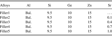
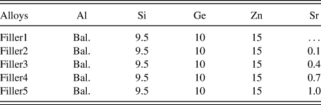
The compositions of filler metals used in this study are listed in Table I. Pure Al (99.7% purity), 99.999% purity Si, Ge, Zn were used in the study to prepare Al–Si–Ge–Zn filler metals, and Sr was added using an Al–10Sr master alloy. To get a homogeneous composition within the filler metals, the alloys were remelted at least 3 times. The melting temperature of these alloys were determined by differential thermal analysis (DTA), which was heated from room temperature to 720 °C under nitrogen atmosphere at a heating rate of 10 °C/min. The microstructure characteristics of the alloys were analyzed by scanning electron microscopy (SEM) equipped with an energy dispersive spectrometer (EDS). The phases observed in the microstructure were identified with an x-ray diffraction (XRD). A nanoprobe beam was adopted for composition analysis using energy dispersive x-ray spectrometry in high angle annular dark field-scanning transmission electron microscope (HAADF-STEM) mode.
Chemical compositions of the filler metals (wt%).
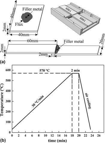
Wetting and brazing experiments were carried out in the tube type resistance furnace, and the improved AlF3–KF–CsF flux was used in the experiment, whose melting temperature ranges from 510 to 530 °C. The wetting test was carried out at the temperature of 570 °C for 2 min with 0.1 g filler metals. The brazing experiment was also performed at 570 °C for 2 min, and 0.15 g filler metals were used. The base metal is 6061-T6 aluminum alloys with dimensions of 40 × 40 × 2 mm for spreading test and 60 × 20 × 2 mm for tensile test, as shown in Fig. 1(a). The heating rate was set at 30 °C/min to the brazing temperature of 570 °C for a dwell time of 2 min. After the brazing, all the specimens were removed from the brazing furnace immediately and air-cooled to room temperature [see Fig. 1(b)]. The solidus and liquidus temperatures of the 6061 aluminum alloy used in this study were 592 °C and 654 °C, respectively. To ensure the accuracy of results, five specimens were tested under the same conditions with each filler metals.
Schematic illustration of the brazing joint (a) and brazing cycle (b).

After brazing, shear tests were conducted using a tensile testing machine at a tensile speed of 1 mm/min. SEM coupled to EDS was used to observe interfacial microstructure and fracture morphology of brazed joint.
III. RESULTS AND DISCUSSION
A. Effect of Sr modified on the microstructure of Al–Si–Ge–Zn filler metal
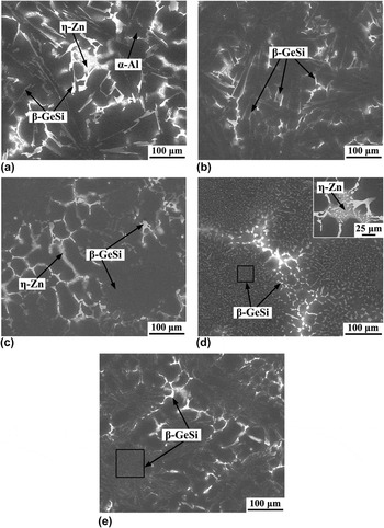
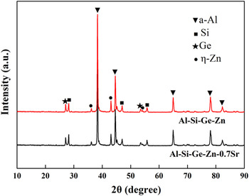
Microstructure of Al–Si–Ge–Zn alloy without Sr addition, as shown in Fig. 2(a), was composed of α-Al solid solution, coarse needle-like brittle β-GeSi phase and η-Zn solid solution. The microstructure almost had no significant change when the Sr content was increased to 0.1 wt%, as shown in Fig. 2(b). When 0.4 wt% Sr was added into the Al–Si–Ge–Zn alloy, the needle-like β-GeSi phase was transformed into lamellar and blocky shape, as shown in Fig. 2(c). With the Sr content increased further, the microstructure underwent a more significant change. As shown in Fig. 2(d), Sr addition up to 0.7 wt% resulted in much finer microstructure, in which most β-GeSi phases were distributed more dispersively and the size of phases became smaller. However, as the Sr content was further increased to 1.0 wt%, as shown in Fig. 2(e), the size of β-GeSi phase had a tendency to expand. It can be concluded that the excessive addition of Sr made the microstructure deterioration. Figure 3 shows the XRD pattern of Al–Si–Ge–Zn and Al–Si–Ge–Zn–Sr filler metals. Unfortunately, the amount of Sr in the filler metal was too small to be observed by SEM.
Microstructures of (a) Al–9.5Si–10Ge–15Zn, (b) Al–9.5Si–10Ge–15Zn–0.1Sr, (c) Al–9.5Si–10Ge–15Zn–0.4Sr, (d) Al–9.5Si–10Ge–15Zn–0.7Sr, and (e) Al–9.5Si–10Ge–15Zn–1.0Sr filler metals.

XRD of Al–Si–Ge–Zn and Al–Si–Ge–Zn–Sr filler metals.

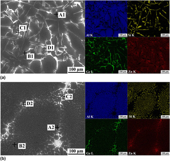
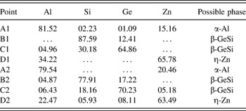
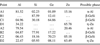
To get more information about the effect of Sr on the microstructure, EDS mapping of the filler metals was done. Figure 4 shows element mapping results of Al–Si–Ge–Zn and Al–Si–Ge–Zn–0.7Sr filler metals. According to Fig. 4(a), the distributions of Ge correspond well with the Si, indicating a uniform doping of Ge in Si phase. Compared with distribution of the major elements in two filler metals in Fig. 4, considerable difference was observed. Particularly, the Ge and Si in the Al–Si–Ge–Zn–0.7Sr filler metal were distributed more dispersively, and the sizes became smaller. The compositions of typical phases in two filler metals are listed in Table II, and the results indicate that the phase A1, A2 is α-Al phase, and D1, D2 is η-Zn phase. Four typical particles are marked as B1, C1, B2, and C2 in Figs. 4(a) and 4(b). It can be obviously found that deep gray particles B1 and B2 mainly contain Si with small amounts of Ge, bright white particles C1 and C2 mainly contain Ge with small amounts of Si. Since Ge and Si are the binary continuous solid solution, these four typical particles (B1, B2, C1, and C2) were deemed to be β-GeSi phases.
EDS element mapping of (a) Al–Si–Ge–Zn and (b) Al–Si–Ge–Zn–0.7Sr.

EDS results of chemical compositions (at.%) of points marked in Figs. 4(a) and 4(b).
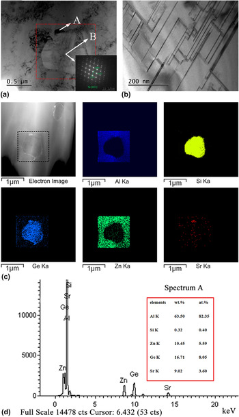
Based on the mechanism of impurity induced twinning, which was first proposed by Hogan et al., Reference Hogan, Kobayashi and Shamsuzzoha19 the obtainment of fine Si phases can be attributed to the adsorption of Sr on the Si surface, which can prevent the growth of the silicon and cause the formation of many twins, thus results in the change of Si phases from coarse needle-like to fine granular shapes. In addition, Sr addition rarely affects the structure of Ge phase, although the Ge possesses similar physical and chemical characteristics with Si. Reference Zhang, Liu and Fan20 Therefore, the morphology change of β-GeSi phases was mainly related to the Si modification caused by Sr. Figure 5 shows the TEM analysis results of fine granular phases in Al–Si–Ge–Zn–0.7Sr filler metal. It can be seen from Fig. 5(a) that the tiny phase A was distributed around the granular phase B. Combining the selected area diffraction (SAD) pattern of granular phase B [Fig. 5(a)] with the element mapping under HAADF-STEM mode [Fig. 5(c)], the phase B was confirmed as β-GeSi phase containing large amounts of Si. Additionally, the bright field TEM image of the phase B shows a large amount of twins in the Si particle, as shown in Fig. 5(b). More importantly, according to element mapping [Fig. 5(c)] and EDS analysis [Fig. 5(d)] results, Sr was observed in the tiny phase A. This detailed TEM observations confirmed that Sr was adsorbed on the Si surface to prevent the growth of Si and cause the formation of many twins in Si. When the Sr is not added into the filler metal, the Si grows into coarse needle-like according to the ledge growth mechanism. After adding Sr, the Sr element was adsorbed on the growth steps of Si to prevent the growth of Si in the form of the ledge growth mechanism. Meanwhile, the adsorption of Sr on Si phase surface also changed the stacking sequence of the Si atoms. Therefore, a large number of twins were produced in Si, and the Si phase grew into fine granular shapes according to the mechanism of twin plane reentrant edge.
Transmission electron microscope (TEM) observation of β-GeSi phase in Al–Si–Ge–Zn–0.7Sr alloy: (a) bright field TEM image and the SAD pattern of granular phase B in which a tiny phase A adsorbed; (b) bright field TEM image corresponding to granular phase B in (a), showing a large amount of twins in the Si particle; (c) element mapping of the phases A and B in (a) under HAADF-STEM mode; and (d) the representative EDS pattern along with the analysis result for the phase A in (a).

B. Effect of Sr addition on melting point of Al–Si–Ge–Zn filler metal
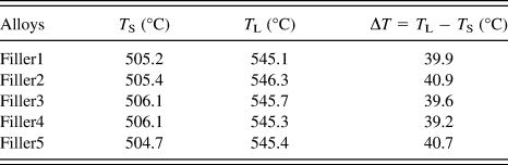
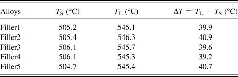
Through DTA analysis, the melting temperatures of Al–Si–Ge–Zn–xSr alloys were determined. The solidus and liquidus of these filler metals obtained from the DTA tests are listed in Table III. It can be seen that the effect of Sr addition on the melting temperatures of Al–Si–Ge–Zn alloy was small. The slight difference of melting temperature interval can be attributed to the difference of morphology and the distribution of the microstructure. Uniform and fine microstructure structure promotes filler metal rapid melting. Reference De Cristofaro and Bose21 The Al–Si–Ge–Zn–0.7Sr filler metal possesses a melting temperature ranging from 506.1 °C to 545.3 °C. The narrow melting temperature interval is favorable for the brazing process. Reference Chuang, Tsao, Tsai, Yeh and Wu22
Melting points of the filler metals.
C. Effect of Sr addition on wetting properties of Al–Si–Ge–Zn filler metal
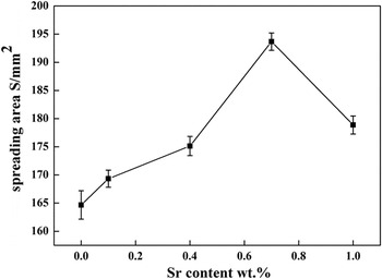
The wetting behavior of Al–Si–Ge–Zn–xSr alloys was investigated by testing the spreading areas of filler metals. Figure 6 shows the results of the wettability test. It can be seen that the spreading area of the Al–Si–Ge–Zn–0.7Sr brazing alloy is 194.5 ± 1.5 mm2, which is 17.8% larger than that of Al–Si–Ge–Zn filler metal. This improvement in wettability is due to the narrow melting temperature interval. Moreover, spreading area of filler metal may be increased, if it possesses a highly refined grain size. Reference Jacobson, Humpston and Sangha23 The fine grain structure helps promote uniformity and rapid melting because the discrete phases are finely divided and the alloy tends toward homogeneity. However, adding excess Sr into filler metal could cause decrease of spearing area due to the grain coarsening and oxidation of the Sr. Reference Shi, Yu, Li, Xia, Lei, Li and Guo24 Thus, with further increase of Sr content up to 1.0 wt%, that disadvantage has affected the wettability of Al–Si–Ge–Zn filler metal. Therefore, it is suggested from the test results that the appropriate addition of Sr should not be more than 1.0 wt%.
Effect of Sr content on spreading area on 6061 alloy.

D. Effect of Sr addition on the microstructure and properties of brazed joints
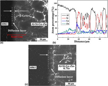
To study the effect of Sr modified on brazeability of 6061 alloy, Al–Si–Ge–Zn–0.7Sr filler metal was used to braze 6061 aluminum alloy at 570 °C for 2 min. In addition, the results would be compared with joint brazed with Al–Si–Ge–Zn alloy. The interface microstructures of the joints brazed with Al–Si–Ge–Zn and Al–Si–Ge–Zn–0.7Sr filler metals are shown in Figs. 7(a) and 7(c), respectively. It can be seen from Fig. 7(a) that the main phases in the brazed seam were α-Al and needle-like β-GeSi phases. From the line-scanning of the 6061/Al–Si–Ge–Zn interface in Fig. 7(b), the diffusion of Zn occurred from the brazed seam to the base metal during the brazing process. A diffusion layer (∼13 μm) was observed between the 6061 aluminum alloy and Al–Si–Ge–Zn filler metal, which was favorable to improve the strength of brazed joint. Reference Bokstein, Ivanov, Oreshina, Peteline and Peteline25 As shown in Fig. 7(c), the small granular β-GeSi phases were found in the brazed seam when the joint was brazed with Al–Si–Ge–Zn–0.7Sr filler metal. In addition, comparing Fig. 7(a) with Fig. 7(c), it can be seen that the thickness of diffusion layer was increased clearly (∼26 μm). Therefore, the addition of Sr modified not only the microstructure of the filler metals but also the brazed joints.
Interfacial microstructure of 6061 aluminum alloy brazed joints: (a) 6061/Al–Si–Ge–Zn interface; (b) interfacial major element content distribution in (a); and (c) 6061/Al–Si–Ge–Zn–0.7Sr interface.

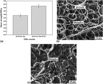
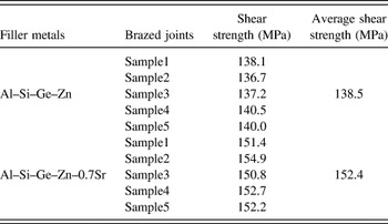
Figure 8 shows the shear strength and fractography of the 6061 aluminum alloy joints brazed with the two kinds of filler metals, and the shear strength results can be seen from Table IV. The shear strength of joint brazed with Al–Si–Ge–Zn filler metal was 138.5 ± 2 MPa [Fig. 8(a)]. It can be seen from Fig. 8(b) that massive dimples appeared on the fracture surface. However, brittle β-GeSi phases were distributed at the bottom of dimples, which is unfavorable for brazed joint strength. It also can be seen from Fig. 8(a) that the shear strength of joint brazed with Al–Si–Ge–Zn–0.7Sr filler metal achieved 152.4 ± 2.5 MPa, 10% more than that of brazed joints with Al–Si–Ge–Zn filler metal. The dimples in the Al–Si–Ge–Zn–0.7Sr fracture were much smaller and deeper than Al–Si–Ge–Zn alloy, as shown in Fig. 8(c). Therefore, Sr addition significantly improved the shear strength of 6061 aluminum alloy brazed joints, which can be attributed to the small granular β-GeSi phases and wide diffusion layer caused by Sr.
Shear strength and fractographs of 6061 aluminum alloy brazed joints: (a) shear strength; (b) fractography of the Al–Si–Ge–Zn brazed joint; (c) fractography of the Al–Si–Ge–Zn–0.7Sr brazed joint.

Shear strength results of joints brazed with and without Sr addition.

IV. CONCLUSIONS
In summary, the effect of Sr additions on the microstructure and properties of filler metals and brazed joints were investigated. From the above study, the following results can be concluded:
-
(1) Sr can effectively refine microstructure of Al–Si–Ge–Zn filler metals. Especially, appropriate Sr addition could effectively change the morphology of β-GeSi phases from coarse needle-like to fine granular shapes.
-
(2) There was no significant change of the melting point of the filler metals after the addition of Sr into the Al–Si–Ge–Zn alloys, yet trace amounts of them greatly improved wettability of the alloys. The spreading areas of the filler metals increased firstly and then decreased with the increase of Sr addition.
-
(3) Sr addition also improved the microstructure of brazed joint with small granular β-GeSi phases and wide diffusion layer. The shear strength of joint brazed with Al–Si–Ge–Zn–0.7Sr filler metal achieved up to 152.4 ± 2.5 MPa, and the fracture of the Al–Si–Ge–Zn–0.7Sr joint exhibited much finer and deeper dimples than that of the Al–Si–Ge–Zn brazed joint.
ACKNOWLEDGMENT
This research was sponsored by the Guangdong provincial science and technology project, China (2010A080402014).